
A network control center always performs these tasks:
It connects the local network to the Internet through a modem and a telephone line, cable TV service, or some other medium.
It uses a router to translate addresses between the LAN and the Internet.
It uses a hub or a switch to exchange data within the network.
It acts as the central distribution point for data cables.
In addition, it might also include these services:
A base station for Wi-Fi
A distribution center for audio, video, and telephone connections
If you're working from the floor plan you created after reading Chapter 5, you have already chosen a location for your control center. If not, find a place that is easy to reach but away from day-to-day traffic: the inside wall of a walk-in closet, a utility room, or a basement wall are all common choices. A garage that's built into the house might be another good spot. The control center should be close to at least one dual AC power outlet.
A network control center can take several forms:
- A modular "structured wiring center"
Several manufacturers offer structured wiring cabinets and most of the switches, routers, and other control devices necessary to assemble a network control center. The panel mounts on a wall (or between the studs in an unfinished basement or garage) and can include a cover to keep the contents clean and out of sight. These panels and components are considerably more expensive than separate parts from different sources, but they present a finished appearance that might be important if the control center is in a conspicuous location. If you're using one of these systems, follow the installation instructions supplied with each component.
- A sheet of plywood attached to the wall
A half-sheet (4 feet by 4 feet) of plywood securely bolted to wall studs is entirely adequate to support your network's mounting blocks, control devices, and other equipment. It might not be as attractive as a structured wiring center, but you're not going to see it very often. If you do a neat, workmanlike job, it will work just as well as a fancy sheet-metal cabinet full of matched components.
- A freestanding mounting frame or cabinet
If you have enough floor space in your utility room, you can assemble the control center from equipment and shelves that mount in a 19-inch-wide relay rack. This approach is usually limited to larger networks that include a lot of locations and equipment.
- Several wall-mounted outlets and a small number of control devices (modem, router, and/or switch) on a table or shelf
If your network is limited to computers in just two or three rooms, it might be easiest to choose one of those rooms as your control center and place the modem, router, and switch near the computer (but remember to allow for additional network nodes in the future). A single wall plate can hold up to six data outlets, so it's possible to run cables to several other rooms without installing an industrial-looking row of mounting blocks.
A data outlet block is the transition between internal data wiring inside a wall and a socket for a cable with Ethernet plugs at each end. Terminating each cable from another room with an outlet will make it easier to make additions and changes to your network wiring.
One side of an outlet block has a set of slotted pins that each holds one of the wires inside a data cable, and the other side has a socket for an Ethernet plug. A data outlet can be located on the side of a small box attached to a baseboard (or to the plywood base of your control center) or on a flush-mounted wall plate. Figure 6-2 shows an outlet block, with cables connected to both sides. The cover has been removed to make the individual wire connections visible.
A completed control center on a plywood panel will look something like Figure 6-3.
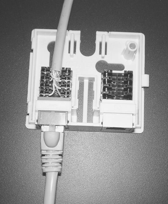
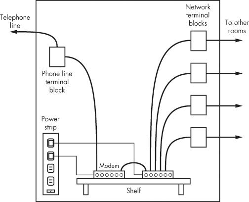
Figure 6-3. A homebrew control panel should include connections for AC power, DSL or video, and several data outlets, along with your modem, router, and switch.
Your modem, router, and switches will all need some kind of electric power. If you're using a plywood panel as your control center, attach an AC power strip with enough outlets for all your devices and at least one spare to the side of the panel closest to the nearest AC outlet, near the bottom. The control panel should be close enough to an outlet that the cable attached to the power strip can reach it without an extension cord. In order to protect your equipment from damage caused by lightning strikes or other power surges, use a power strip with a built-in surge protector.
Many network devices use plug-in transformers or power converters (sometimes called "wall warts") that are bigger than a simple AC power plug, so you will want a power strip that provides extra space between outlets, like the one shown in Figure 6-4. This particular model also includes surge protection for a DSL telephone line.
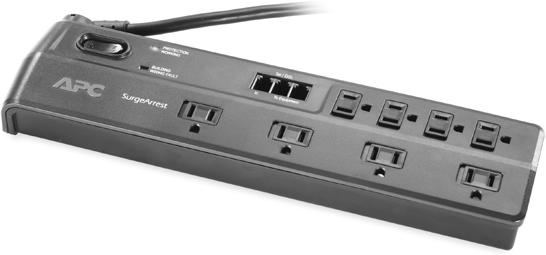
Photo courtesy of APC
As an alternative to a power strip, consider using an uninterruptible power supply (UPS) that will provide backup power from a battery when your AC power fails. A UPS is not a replacement for a generator, but it will keep your network alive during short power disruptions. Network control devices don't use as much power as a computer and monitor, so a small UPS should be enough to keep your network alive for up to an hour. Of course, during a power failure you will be able to use the network only with laptops and other battery-powered portables.
The battery in a UPS is relatively heavy, so you will probably want to place the UPS on the floor rather than on a shelf on the control panel. If the UPS does not have enough battery backup outlets for all of the equipment in your control center, plug a power strip directly into an outlet on the UPS.
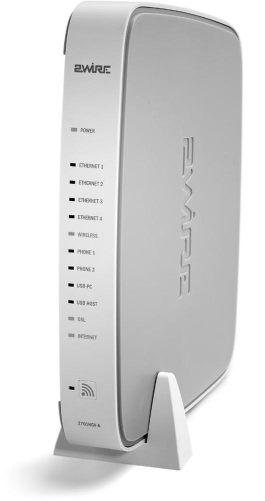
If you already have broadband Internet service, take a close look at the modem that connects your computer to the telephone line or TV cable and the instruction sheet that was provided with the modem. Some Internet service providers supply modems (such as the one shown in Figure 6-5) that double as gateway routers, switches, and/or Wi-Fi access points. If you have a combined unit, there's no need to duplicate those functions with one or more separate boxes.
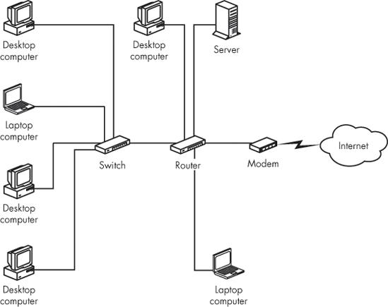
Your floor plan should contain enough information to tell you the number of nodes in your network. You will need one port on a switch or combined switch/router for each node, plus additional ports to connect the control devices. For example, if you have a total of seven nodes in your network, you might use these control devices:
Figure 6-6 shows how these devices connect to one another.
You can find switches and routers at many office supply and electronics stores and through online retailers. It seems as if one brand or another is almost always on sale, so it's worth looking at the advertisements in the Sunday newspaper for this week's hot deals.
If possible, your router or switch should have at least one spare port that you can use with a laptop computer. When you're trying to troubleshoot the network, it's often convenient to send commands from the computer while you watch the responses to those commands on the control devices' status lights.
When you add more nodes to the network in the future, you can expand the network by connecting an additional switch to the control center. If there are no spare ports on the existing switch, disconnect one cable from the active switch, connect the new switch to that port, and plug the original cable into the new switch.
Some switches and routers have keyhole slots on the bottom of their cases that allow you to mount them directly on a wall, like the ones shown in Figure 6-7. When you mount a device on a wall panel, place it below eye level, with the front panel at the top of the box, so the status lights are easy to see.
If there is no allowance for mounting holes on your modem, switch, or router, and you're using a wall-mounted control center, attach a 6-inch shelf to the plywood panel and place the devices on that shelf. If you're using a modular structured wiring center, there's usually space at the bottom of the cabinet that you can use as a shelf. For a rack-mounted control center, use a rack shelf for any devices that don't mount directly into the rack.
Use big wire staples from the hardware store to route the power cables neatly along one side of your control panel between each control device and the power strip. Don't mash the staples all the way into the plywood; allow some space to be sure you haven't crushed any of the wires. Be sure to leave enough slack wire at the back of each device to allow yourself to unplug the power connector easily.
Broadband Internet service comes into your building through either a telephone line or a TV cable. Therefore, you will need either a telephone or cable TV outlet in your control center. This is the same kind of outlet that you are already using to connect a telephone or TV set. If you're getting Internet service from your cable TV company, you can sometimes convince the installer to run a cable to your control center. But if you have DSL or some other type of Internet service from the telephone company, you might have to install your own wiring.
If you have DSL or some other kind of Internet service from the telephone company, you will need a telephone outlet with a four-pin socket called an RJ-11 jack. This is the same kind of socket that you use to plug in a telephone set.
Mount the outlet block on your panel, about a foot above the power strip. You can use either conventional telephone cable, with two pairs of wires inside, or the same four-pair data cable that you use for your computer network to connect the outlet block on the control panel back to the distribution block that connects your telephones to the service entry. If you use telephone cable, be sure to match the colors of the wires to the letters on the outlet blocks at both ends (R = red, Y = yellow, G = green, and B = black). If you use data cable, use the color codes in Table 6-1.
Table 6-1. Data Cable Color Codes for Telephone Lines
Terminal Color | Data Cable Color |
|---|---|
Green | Blue |
Red | Blue-White |
Black | Orange |
Yellow | Orange-White |
Use a cable-stripping tool to remove about two inches of the plastic jacket from the end of the telephone cable. If the outlet block has screw terminals, strip about half an inch of insulation off the end of each wire and wrap the bare end around the screw next to the letter that corresponds to the wire's color.
If the terminal uses two vertical pins with a slot between them to hold each wire, don't strip the wires, but use a punch-down tool to force each wire between the pins. If your terminal does not come with a small punch-down tool, look for one at a home center or hardware store; you will need the same tool to connect data cables to their outlet connectors. If excess wire extends from the side of the connector, cut it off. When all four wires are connected, place the dust cover on the plug.
After you have connected the telephone line to the outlet block, plug in a telephone with a modular RJ-11 cable to test for a dial tone. If there's no dial tone, check your connections at both ends; if you have a dial tone, unplug the telephone set and use one of the cables supplied with the modem to connect the modem to the telephone line.
Most video wiring inside a building uses coaxial cable called RG6/U with a central copper wire surrounded by insulation and a metal shield. The connectors that attach to this cable are called F connectors.
Video cables usually require a special tool to attach the F connector to each end of the cable. If you're not installing your own video distribution system along with your data network, and you have to install your own cable from the service entry to the network control center, it might be easier and cheaper to buy a pre-assembled cable with the connectors already attached (look for a cable close to the length you need—don't use a 100-foot cable for a 20-foot run). Use electrical tape or a cable tie to hold excess lengths of cable in a neat loop at one end.
If you have to install the video cable yourself, find the service entry where the cable comes into your house or office. String the cable along the ceiling or through the rafters under the floor to the control center, then attach the cable to the F connector inside the outlet plate. If there's a splitter with a spare connector at the service entry, screw the plug at the end of the cable onto the unused socket. If you can't find a splitter, you'll have to install a new one, or distribute your video from the control panel.
If you're not connecting other outlets through the control center, plug the cable from the service entry directly into your cable modem. If you want to use the control panel to distribute cable TV signals to outlets throughout the house, connect the cable from the service entrance to the input of a splitter and connect the outputs to your cable modem and the cables from each room.
If you're using a plywood panel as your control center, mount one or two rows of outlet blocks along the top of the panel, or along the side opposite the power strip. Keep the outlets evenly spaced and allow enough space to add more outlets in the future.
Terminate the wires in each network cable on a terminal block with an eight-pin RJ-45 socket (be sure to follow the color codes) and attach a tag to the cable that identifies the location of the cable's other end. Use a marking pen or the label supplied with the terminal block to identify each cable on the cover of the block. Your goal is to be able to figure out at a glance which terminal block connects to what destination.
There are two different standard color codes for connecting Ethernet cables to plugs and sockets. Use one of the standard color codes (T568A or T568B) to connect each wire in the cable to the socket inside the terminal block. Table 6-2 shows the correct connections. It doesn't matter which of the two standards you use, as long as both ends of each cable follow the same standard. The best approach is to choose a standard and wire every socket in your network to that standard.
Table 6-2. Wiring for Ethernet Cables and Sockets
Color | T568A Pin Number | T568B Pin Number |
|---|---|---|
Blue | 4 | 4 |
Blue-White | 5 | 5 |
Orange | 6 | 2 |
Orange-White | 3 | 1 |
Green | 2 | 6 |
Green-White | 1 | 3 |
Brown | 8 | 8 |
Brown-White | 7 | 7 |
Follow these steps to connect a CAT5, CAT5e, or CAT6 cable to an Ethernet socket:
Allow about a foot of slack and cut off the excess cable.
Remove about two inches of the cable's outer jacket. Be sure you don't nick any of the internal wires with your stripping tool.
Separate the four pairs of wires that extend beyond the jacket, but don't untwist the individual wires.
Follow the instructions supplied with the connector to direct each wire to the correct slot. Be sure the jacket extends into the back of the connector.
Use a punch-down tool to insert the two wires closest to the back of the connector into their respective slots.
Insert the wires from the other three pairs into the correct slots. Don't untwist the pairs any more than is necessary.
Double-check to confirm that each wire is in the correct slot according to the color code you are using.
If your punch-down tool doesn't automatically cut off excess wire, use a wire cutter to trim each wire.
If the RJ-45 socket came with a dust cover, snap it into place over the wires.
Insert the socket into the terminal block or the wall plate from the inside of the block or case.
When you're trying to solve a problem with your network connection, it's often helpful to have a telephone next to the control panel, so you can talk to a technical support person while you're looking at the status lights on the modem, router, or switch. You won't need this phone very often, but when something goes wrong, you will be happy to have it. Use a cell phone or a cordless handset if you have one, or install an inexpensive wall phone on or near the control panel. If possible, look for a simple desk or wall phone that does not require an external power supply.