
IMAGE DISPLAY AND CAPTURE DEVICES
The two essential ends of a video or TV system are the image pick-up device in the camera or telecine, and the display system in the TV set. Many years ago that implied an electron-scan (cathode ray) tube at both ends, and while a thermionic tube is still there in most TV sets and monitors, image scanners are now made of silicon photodiode arrays, while some specialised TVs and monitors use liquid-crystal screens, generally very small ones or very large projection types. In this chapter we shall examine them all, and look briefly at the older technology of TV camera tubes, starting with the most common display system, the thermionic picture tube. Although black-and-white tubes are seldom seen except in miniature form as camcorder viewfinders, an understanding of their operation is an essential stepping-stone to an appreciation of colour picture tubes.
SINGLE GUN TUBE
Fig. 5.1 shows the make-up of an electrostatically focused monochrome display tube. Electrons are emitted by a cathode (K) maintained at dull red heat by an internal heating element. The negatively charged electrons are attracted towards the first anode (A1) which is positive with respect to the cathode. The first anode consists of a skirted disc with a small central hole through which most of the electrons are accelerated. Closely surrounding the cathode is a cup-shaped elecrode called the grid (G) which also has a small central hole. By varying the potential on the grid, typically within the range −25 V to −100 V with respect to the cathode, the density of electrons in the beam can be varied: phosphor brightness depends on beam density, so the instantaneous brightness of the scanning spot can be varied at fast rate by feeding a suitable modulating voltage between cathode and grid; this will normally be the video signal. Provided the scanning spot is in the right place on the screen at the right time a pattern of light and dark picture elements is built up to form a complete picture.
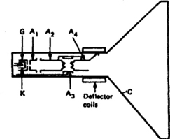
The second and fourth anodes are connected to a conductive layer (C) on the inside of the bowl of the tube, which itself forms a wall anode. Between anodes 2 and 4 comes the focus electrode A3, a cylindrical anode whose potential (typically variable between +400 V and +800 V d.c. with respect to the cathode) determines the focusing point of the electron beam.
Anodes 2 and 4, the wall anode and the inner screen surface are together connected to a source of very high voltage (e.h.t.) which may vary between 5 kV in camera viewfinder tubes and 28 kV in very large-screen colour tubes. This voltage gives the screen-bound electrons tremendous acceleration.
The screen in a monochrome tube is coated with a phosphor, usually composed of a mixture of blue-emitting zinc sulphide and yellow-glowing zinc cadmium sulphide. The combination gives an approximation to white light emission when bombarded with electrons. The phosphor screen is backed by a film of aluminium which has three purposes: It acts as a barrier to heavy ions, preventing them burning the phosphor layer; it reflects phosphor-light forward into the viewing area; and it equalises the electrostatic charge over the entire screen area, preventing spurious local beam-deflection effects.
BEAM DEFLECTION
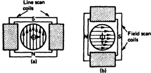
The square of light on which the picture is built up is called a raster, and to trace it out on the screen of a picture tube the electron beam must be deflected vertically and horizontally. The process is almost invariably a magnetic one in which deflection coils (Fig. 5.2) generate lines of magnetic flux in the tube neck. Note that vertical lines of force are responsible for horizontal deflection and vice versa. The angle through which the scanning beam is turned between opposite corners of the raster (i.e. across the diagonal) is the deflection angle. For medium and large monochrome tubes it is generally 110°. Many colour tubes also have 110° deflection, though 90° deflection is very common, and eases power-consumption and convergence problems. Very small screen tubes have much smaller deflection angles; 50° and even 23° may be encountered.
COLOUR PICTURE TUBE
To build up a colour picture three separate primary colours are used – red, green and blue. Combinations of these three can make almost any colour, including white; by adjusting the three colour intensities to obtain white and then regulating the brightness of all three together different brightnesses of white can be achieved, permitting the reproduction of a monochrome picture if required.
The construction of a colour tube is shown in Fig. 5.3. A single gun is used, working in similar fashion to the monchrome gun assembly already described, but containing three separate but closely spaced cathodes. These cathodes are mounted in-line abreast, and the other electrodes in the gun assembly each have a row of three pinholes aligned with the electron beams emerging from the triple cathode array. As the three beams travel along the tube neck they are accelerated and focused by the anodes in the gun assembly, each to come to a sharp point of focus at the surface of the screen.
Colour screen
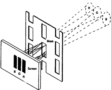
The rear of the screen of a colour picture tube is composed of a large number (typically 600 across the screen width of a large tube) of vertical stripes of phosphor material. The stripes are laid in the sequency RGBRGB etc. across the screen width. Red-emitting phosphors are made of a rare-earth material yttrium/oxysulphide/europium, while the other two are based on zinc sulphide with silver admix for blue and a copper/aluminium admix for green. The rear surface of the phosphor layer is aluminised, the thin coat of aluminium reflecting the phosphor light forward, equalising the electrical charge over the screen area, and preventing ion burn to the phosphors. The rear (gun side) of the aluminising layer is sprayed black to help in dissipating the heat developed by the shadowmask and screen.
Shadowmask
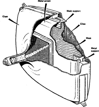
Mounted some 12 mm behind the tricolour phosphor layer is the shadowmask (Fig. 5.4). The shadowmask is the main feature of all direct-viewing colour picture tubes and its function is to act as a filter, permitting the electron beam from each cathode to strike only its own phosphor material. As they approach the screen the three separate beams are on converging paths, with approach angles typically 1o apart. The beams cross over as they pass through the slots in the mask, and diverge beyond to impinge on their respective phosphor stripes. For each phosphor stripe the ‘wrong’ electron beams are shadowed by the mask, so that each beam (provided its approach angle is correct) can only see through the mask to its own phosphor stripe, and this applies regardless of the degree of deflection it suffers in its passage through the deflection field. Thus is set up the condition whereby three separate but superimposed fields of primary colour, red, green and blue, can be produced on a single screen, each field being separately controlled by the bias applied to its own cathode with respect to the common grid plate.
The shadowmask is inherently inefficient in that most of the energy in the three beams is intercepted by the steel mask itself; only about 25% of the beams’ energy reaches the phosphors, the rest being dissipated as heat in the mask itself. On very high brightness scenes the dissipation in the mask can exceed 20 W, and the effect of the resulting heat is to expand the mask. Any resulting buckling or distortion will upset beam landing accuracy and lead to impurity, in which the beams strike the wrong phosphor stripes, staining the picture with patches of incorrect colour. To prevent this the shadowmask is secured to the inside of the glass envelope by special mountings which permit the expansion to be taken up by moving the entire mask axially (i.e. towards or away from the screen) in such a way that beam landing accuracy is maintained. A typical mask mounting arrangement is shown in Fig. 5.5.
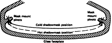
Fig. 5.5 Shadowmask expansion and mounting, not to scale. The mask mountings are in the screen corners.
In the tube manufacturing process the mask and screen are aligned and fitted to a ‘lighthouse’ machine to fix the phosphors. In a three-stage process, phosphor material for each colour is coated over the entire screen area then ‘fixed’ in the correct shape, width and position by shining a powerful xenon lamp through the mask. Since the light source is in exactly the position subsequently occupied by the apparent beam origin for each phosphor in turn, provided that the beams are correctly positioned and angled during the operation of the tube, perfect purity will result.
PURITY ADJUSTMENT
When the colour tube is in operation the origin of the beams (so far as the shadowmask is concerned) is the deflection centre, a point in the tube neck at the centre of the deflection coil assembly. The electron beams have to be manipulated to bring them to the correct deflection centre, and this is achieved by a pair of ring magnets (on the neck of the tube) whose two-pole field can move all three beams together sideways to correctly align the trajectories of the beams through the deflection centre. Adjustment of these purity ring magnets will give correct purity at screen centre, but at large deflection angles (i.e. towards screen edges) some impurity may be present. To eliminate this the deflection centre itself must be aligned axially by sliding the entire deflection yoke assembly along the tube neck, fixing it in position where full-screen purity is obtained. In practice there is a small ‘sliding range’ over which good purity obtains – for best tolerance and to provide for various drift influences the yoke should be fixed in the middle of this range.
CONVERGENCE
In setting up the purity, provision is made to reserve each phosphor for its own beam, but this does not mean that the patterns produced by the three beam/phosphor combinations will exactly overlay each other, an essential requirement when a composite picture is to be formed from three superimposed colour pictures. Any lack of registration will give rise to colour fringing on edges and outlines of picture features. In most colour tubes the green cathode is central in the gun and the green beam travels down the centre of the tube neck to trace out a square, central picture on the screen. Because the outer beams, red and blue, take a different path and angle through the deflection system their patterns suffer from deflection distortion preventing either from overlaying the green pattern. Steps must be taken to exactly register the three images on screen: they take two forms, static convergence and dynamic convergence.
Static convergence
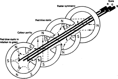
Although the dimensional and alignment tolerances in electron-gun manufacture are very tight, it is not possible to fabricate and fix the gun accurately enough to ensure that the centres of their on-screen images coincide. Centre-screen registration is called static convergence, and depends on the position of each beam-path within the tube neck. To correctly align these, a series of ring-magnet pairs is fitted on the tube neck forward of the purity rings already described. Their magnetic fields are carefully tailored to cross the paths of the outer (red and blue) electron beams while having no effect (in fact, no magnetic field) on the axis of the tube neck where passes the central green beam’s path. By means of a pair of four-pole magnets whose field intensity and direction can be varied by co- and contra-adjustment, the outer beams’ paths are moved horizontally and vertically so that their images coincide at screen centre to give a magenta (red plus blue) spot there. The position of this magenta spot will not necessarily coincide with that of the green spot, so a further ring-magnet pair, this time with six-pole field, is fitted to the tube neck.
The six-pole magnetic field set up by this third ring pair is again adjustable as to strength and direction, and because its flux patterns appear identical to the outer beams they are together moved in either a horizontal or a vertical plane so that the magenta and green images can be superimposed. Fig. 5.6 shows a typical neck magnet cluster with the effect of each ring-magnet pair on the paths of the beams. In some tube designs these neck magnet systems are not used. The required magnetic fields for tolerance correction in terms of purity and static convergence are permanently ‘printed’ into a single ring at the top of the gun assembly during the manufacturing process.
Dynamic convergence
Unfortunately the achievement of perfect convergence at screen centre will not alone ensure that the registration holds correct right out to the screen edges. As the beams are deflected away from screen centre the fact that the screen is flat rather than spherical means that the deflection-centre-to-screen path becomes longer. The beams converge at the image plane, an imaginary sphere centred on the deflection centre, and diverge beyond it to strike the screen at widely different points. A solution to this problem is to take advantage of the slightly different paths of the beams through the deflection centre, and carefully shape the latter’s magnetic field to impart a corrective factor to the deflection force applied to individual beams. By very precise control of the physical position of each turn of wire in the line and field deflection coils, the shape of the flux-field each generates in the tube neck can be controlled. For a self-converging tube the vertical lines of force responsible for horizontal deflection need to conform to a pincushion shape, and the horizontal lines of force which deflect the beams vertically to a barrel shape, as shown in Fig. 5.7.
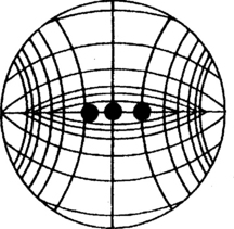
Fig. 5.7 Shapes of magnetic deflection fields for a self-converging colour tube. The central spots depict the beams; the lines represent lines of magnetic force
These magnetic field patterns depend entirely on the physical shape and arrangement of the saddle-wound deflection yoke and the configuration and shape of the winding. In some designs manufacturing tolerances of tube and yoke are not sufficiently good to ensure perfect convergence at the extreme edges and corners of the picture. To take up these tolerances the front (flared) end of the deflection coil is made larger than the tube bulb flare, permitting the front of the yoke to be panned and tilted for optimum screen-edge convergence. When it is achieved the yoke is wedged and sealed in position. In a tube with green gun central, horizontal panning of the yoke has the effect of registering red and blue lines parallel to and adjacent to the screen edges, while vertical tilting of the yoke registers the extremities of the red and blue lines which pass through screen centre. In some deflection systems a four-pole electromagnet is fitted to further assist with dynamic convergence. It carries sawtooth and parabola waveforms at line and field rate, whose amplitude and shape are adjustable by six or so resistive or inductive trimmers. Differential adjustment of the currents flowing in the two halves of each deflection coil pair (scan balance controls) may also be provided to correct crossover of red and blue horizontals on the screen centre-line.
TUBE SETTING UP
A typical set-up procedure for an in-line tube with green gun central, and adjustable neck rings and yoke is as follows: Allow 20 minutes for tube warm-up, then switch off red and blue guns and pull back the deflection yoke towards the guns. Adjust the two-pole purity ring magnets for a central green stripe on the screen, then push the yoke forward for a full pure green screen. Clamp the yoke securing band at the middle of the range over which there is no effect. Restore red and blue beams, switch off green and adjust the four-pole rings to overlay blue and red images at screen centre. Restore green beam and manipulate the six-pole ring pair to overlay green and magenta images to render a white cross or dot at screen centre. Finally tilt and pan the front end of the deflection yoke to achieve best possible convergence at screen edges, then fix and seal the yoke position with rubber wedges and silicon rubber compound.
TRINITRON TUBE
A variant of the in-line gun design is the Trinitron tube illustrated in Fig. 5.8. Its main difference from the tube already described is the omission of the tie-bars in the shadowmask to render an aperture-grille structure in place of the slot-mask; and the arrangement of the gun, in which the two outer beams cross over in the middle of the gun assembly.
The focus anode and its adjacent electrodes form an electron-lens, and as in optical lens technology the larger the lens diameter the better its performance. The effect of the Trinitron gun assembly is to pass all three beams through the centre of a large lens assembly for less aberration and smaller spot size than is easily possible with the small separate electron lenses of other types of gun assembly.
Static convergence is carried out in the Trinitron tube by means of concentric convergence electrodes which have a prism-like effect on the electron beams. The differential electrostatic deflection they introduce is adjusted by varying the potential between the plates, and since one set is connected to the final anode, the static convergence control is associated with the e.h.t. source itself, in the form of a highly insulated potentiometer whose output is passed into the picture-tube via a coaxial connector let into the bowl of the glass envelope; the e.h.t. potential enters the tube by the same connector. Other variants of the Trinitron tube have a built-in resistor which forms part of a potential divider with an external variable resistor for adjustment of static convergence.
In other respects, Trinitron tube setting up is broadly similar to the procedure already given, except that wide-angle Trinitron tubes (114° deflection) sometimes require the use of self-adhesive button-magnets on the glass flare to correct minor areas of impurity.
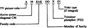
PICTURE-TUBE NOMENCLATURE
The type numbers assigned to different designs of picture-tube have followed various formulae over the years. Tubemakers have now agreed on a worldwide type designation system which is detailed below:
FACEPLATE DESIGN
The darkest parts of a TV picture have the same luminance value as the (unenergised) screen itself, and the darker the faceplate can be made, the greater the perceived contrast of the picture: the ideal viewing screen for a picture-tube would be a flat matt-black surface. In practice the nearest approach to this is to minimise the reflectivity of the screen to ambient light and phosphor light reflected back from the viewers and viewing area.
To this end the spaces between phosphors on the rear of the faceplate are filled with a light-absorbent black pigment based on carbon or graphite, a technology called black matrix. The phosphor material itself is very light in colour, so dyes are added to make each absorb incident light of colours other than its own. The use of these pigmented phosphors, together with black matrixing, reduces the reflectivity of the tube face by 30% or more without any effect on brightness. The benefit can be reaped in terms of either enhanced brightness or contrast, depending on the light transmission characteristic of the faceplate glass.
The faceplate glass characteristic makes an important contribution to picture-tube performance. In effect the glass viewing panel acts as a neutral-density filter, having grey glass with a light transmission factor between 40% and 85%), depending on design. The basic idea of the dark-tinted faceplate, which inevitably reduces picture brightness, is to reduce the screen’s reflectivity and thus increase picture contrast. Reflected light has to pass through the glass twice, while the phosphor-light passes through only once. Thus for a faceplate with 50% transmission a four-fold reduction in reflected light is traded for a halving of the available light from the phosphors. Fig. 5.9 shows the effect of two different glass densities on the contrast ratio; the screen reflectivity factor is based on a modern design with pigmented phosphors and black matrix.

Fig. 5.9 The effect of tinted screens on picture contrast. At (a) a dark faceplate with 42% transmission gives a contrast ratio of almost 6. At (b) a much lighter 85% transparent screen offers only half the contrast ratio, though picture brightness is greater.
Screen shape
The transmitted picture is rectangular, and the more nearly rectangular the viewing screen the better. As picture-tube design progresses the screen is becoming ‘squarer’ and ‘flatter’ though it is difficult, in screen sizes larger than a few centimetres, to make them perfectly rectangular or completely flat due to the effect of atmospheric pressure on the glass envelope. Even so, Sony has produced large flat-screen tubes for consumer applications. The flatter the faceplate, the less ‘capture area’ it has for reflections from the viewing area, the wider its viewing angle, and the less distortion it gives to the picture.
Widescreen displays
In principle widescreen picture-tubes (16:9 aspect ratio) work in exactly the same way as the 4:3 tubes described above, and from which they were developed. The greater horizontal deflection angle imposes more stress on the horizontal output stage – and on the tube designer, whose yoke and gun assembly must be of high precision and close tolerance! For information on compatibility of standard and widescreen pictures see page 212.
TUBE REACTIVATION
The most common fault in picture-tubes is low emission, where the emissive coating on the cathode cannot release sufficient electrons to provide a bright sharp picture. Very often a reactivation process can be successfully applied by overrunning the heater for a few minutes and applying a positive potential to the grid with respect to the faulty cathode. The resulting heavy current disrupts the surface of the cathode, cleaning it and exposing a new surface. Sophisticated machines (see Chapter 23) are able to give controlled reactivation. Other possible gun faults are short-circuits between electrodes – which will turn the afflicted gun hard on, very often on a sporadic basis; and (rarely) an open-circuit heater or electrode, which is not curable except by rebuilding the tube with a new gun assembly. Inter-electrode shorts not involving any heater can often be blown clear by application of high current and voltage, typically from a charged capacitor.
HANDLING PICTURE-TUBES
The atmospheric pressure of the faceplate of a 51 cm tube is around 1600 kg, and over the total surface area is over 4000 kg. Sudden fracture of the glass results in very dangerous implosion, in which jagged fragments of glass can be hurled five metres or more if the tube is not fitted in its cabinet. Always wear protective goggles or a face mask and preferably gloves as well, when handling tubes. Hold the tube vertically screen down with both hands, one under the screen and one steadying the neck with small tubes, one hand on each side of large tubes. Place face down on a soft surface to avoid scratching, and always fit a shorting strap between anode connector, external graphite coating and rimband when removing or handling tubes: this avoids electric shock from the stored e.h.t. potential, particularly dangerous when carrying a tube.
TUBE PROJECTION DISPLAYS
The ‘home-cinema’ industry, and its enthusiastic customers, along with pubs, clubs and discos, have brought about a demand for larger screens than can be afforded with direct-view tubes. In a projection TV using thermionic tubes there are two choices: back-projection, in which the light sources and the (‘ground-glass’ type) screen are together in a large console cabinet; and front-projection, where the projector and the viewers are on the same side of large reflective screen, which – for CRT-type projectors – is concave to increase the reflective ‘gain’ of the screen at the expense of viewing area: seen from a large angle the screen is quite dim. Here the projector is either ceiling-or table-mounted.
For either configuration there are one each of red-, green- and blue-emitting tubes, typically 13 cm in diameter and running beam currents of several milliamps peak from their precision narrowbeam electron guns: this calls in some cases for cooling of their glass faceplates by either liquid or forced air. The tubes are mounted in line abreast and scanned in synchronism by identical deflection yokes, effectively connected in parallel to the common line and field output stages. The central tube (e.g. green) produces, via the optical system, a truly rectangular raster, but the images from the outer tubes – whose axes are necessarily neither coincident nor parallel to the centre tube – are distorted into a keystone shape on screen without correction. It is compensated for by modifying the deflection currents in the scan yokes of the outer pair: in modern sets these registration correction characteristics are held in EEPROM memory and implemented by bus-controlled scan-correction ICs and drivers working on the deflection coils of the two outer tubes. Each tube has its own focus and first-anode voltage presets, plus video-drive adjustments for grey-scale tracking – in sophisticated sets they are automatic in operation. More of this in later chapters of this book. In some ways, and especially in regard to fault-diagnosis and setting up, the three individual tubes correspond to the three guns of the shadowmask and Trinitron tubes already described in this chapter, and the rest of the projection set to the TV receivers which are the subject of the first half of this book.
In front of each of the projection-tube faceplates are optical systems to collect the divergent coloured light and concentrate it into a forward beam. It may consist of a lens or a Schmidt reflector, the latter (in expensive and sophisticated systems) built into the tube itself.
ALTERNATIVE DISPLAY SYSTEMS
The picture-tubes considered so far combine a beam-scanning process with light generation and repetitive spot-intensity modulation which is fine for home viewing and desktop computer VDUs – at least it is a very good compromise between size, cost, complexity and power consumption. In other applications tubes are disadvantaged by their weight, power consumption, shape, limited operation life, light output limitations or such practical factors as the difficulty of making tiny high-definition colour types. These drawbacks come to the fore in the realms of camera and camcorder viewfinders; pocket-portable TVs; laptop computer monitors; stable and bright projection systems; TV and monitor screens in aircraft for leisure and operational roles; and so on. For these applications other display devices have been developed and have undergone intensive development. The most common of them is the LCD array.
LCD panel
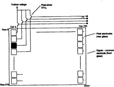
An LCD (Liquid-Crystal Display) display panel consists of tens of thousands (for good, big displays, hundreds of thousands) of individual cells in a matrix on a flat transparent plate. The light coming from behind passes first through a polarising plate so that all the light entering each cell is (e.g.) vertically polarised. If it is allowed to travel thus through to the exit plate it is blocked by the horizontal polarising action of the latter: the cell passes no light. If, however, the light orientation is twisted through 90° in its passage it can get through the exit plate to make a white dot for that cell, see Fig. 5.10. Each cell is filled with liquid crystal, which has the property of twisting its molecular structure in proportion to applied voltage, and a light beam passing through it has its polarisation twisted likewise. Thus the transparency of each cell depends on applied voltage, and if many thousands of such cells are assembled into a matrix of lines and columns – and individually controlled – a picture can be produced from light passing through the plate, with each cell forming one picture element (pixel). Each cell is governed by its own thick-film driver transistor (TFT) formed on the surface of the panel, and addressed individually by the on-board drive circuit, a complex IC array. Fig. 5.11 gives an outline of the system in a 575 × 720 array containing 414 000 individual cells – and 414 000 separate TFTs. For colour displays it is necessary to put coloured filters over individual liquid crystal cells (Fig. 5.12) and route R, G and B signals to the corresponding TFTs; for the same picture definition there needs to be three times as many cells/pixels in a colour display as in a black-and-white one. Direct-view TV and monitor LCD panels have a backlight, generally made from one or more fluorescent tubes with a reflector and diffuser.


LCD projector
Liquid-crystal display panels provide an attractive alternative to electron tubes as a building block in a projection TV set. They do not wear out, are stable in operation and can be made to provide bright pictures with easy adjustment of image size on a screen which does not have to be ‘special’ in any way – any flat white surface is suitable. Fig. 5.13 illustrates the principle on which they work. A powerful metal-halide lamp with even spectral emission forms the backlight. The heat is taken out of the beam, then it is split into its R, G and B primary colours by a series of mirrors and dichroic (colour-discriminating) lenses. Thus each of the three LCD panels sees only one primary colour passing through it, and is fed with the corresponding primary-colour video signal from the colour decoder. The three separate R, G, B beams are recombined in a projector lens for transmission to the screen, which in ‘domestic’ models can be from (e.g.) 1.2 m to 5 m diagonal. Image size is adjusted by a simple optical ‘zoom’ lens: there is a trade-off between picture size and brightness, as with any projection system. In a typical home-cinema projector there are three 7.5 cm LCD panels each containing about 300 000 pixels illuminated by a 250 W metal halide lamp. The panels are force-cooled by a fan to keep them at 50°C or less, monitored by a sensor which cuts off the light at excessive temperatures.
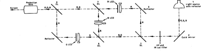
Fig. 5.13 The optical path of an LCD TV picture projector. UV is ultraviolet, IR infra-red, DL dichroic lens, CD condenser lens
The lamp is the most vulnerable component reliability-wise, though a life of several thousand hours may be expected. The bulb is initially fired by a 12 kV arc to vaporise a mercury blob and establish a conductive path between its two electrodes. Thereafter an a.c. current of about 2.5 A at 100 V is passed through the lamp, externally regulated for constant energy level and monitored by the system-control section.
Plasma display
A relatively recent development in flat-screen technology is the gas-plasma display system, in which a gas-filled (low pressure) cell forms each pixel. A discharge takes place when a potential of about 300 V is applied to the anode, and the resulting glow provides a point-light source. In the Sony Plasmatron this technology is combined with that of an LCD display: the plasma discharge acts as a switch to couple the signal data to the LCD cells in complete lines in sequence. This is called PALC, Phase-addressed Liquid-Crystal display. A typical panel of this type offers 256 000 colour variants and 770 × 450 pixels in a 16:9 aspect-ratio configuration on a 63 cm diagonal screen which is less than 4 mm thick.
PICK-UP TUBES
Of the two ‘live-image’ pick-up devices in current use the vacuum photoconductive tube was the first-comer; the more common solid-stage sensor will be described later. The generic term for photoconductive tubes is vidicon, the many other type names arising mainly from the use of different target materials.
A vidicon tube (Fig. 5.14) has an electron gun broadly similar to that described for display tubes, with the difference that the gun is designed for a very small beam current (< 1 μA) and very small spot size – around 20 micron diameter. It has electrostatic focusing, but this is supplemented by a magnetic focusing coil which is coaxial with the vidicon tube. The effect of the static magnetic focusing field is to impart to the individual electrons in the beam spiral paths, which at intervals along the beam length all cross through the same point. Adjustment of the strength of the axial magnetic field by varying the d.c. focus coil current enables one of these focal points to coincide with the target surface at the front of the tube. Another important effect of the magnetic focusing system is to alter the deflection characteristics of the scan yoke to those of orthogonal scanning, in which the scanning beam hits the target at right angles to its surface regardless of the deflection angle involved.
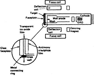
Fig. 5.14 Cross-section of a vidicon pick-up tube: the inset shows detail construction of the target and faceplate
In a vidicon tube the final gun electrode is a wall anode, and a mesh is fitted over its outer end. Between the high-voltage mesh and the low-voltage target layer exists a steep potential gradient, and the electrons travelling down this gradient are greatly decelerated to impinge on the rear of the target at low velocity. The rear surface of the target is now effectively connected to the cathode via the electron beam and is thereby charge-stabilised to the cathode potential.
Vidicon target
The electron beam in the vidicon is not modulated from the gun end of the tube save for blanking during field and line flyback intervals. Even so the beam current does become intensity-modulated as a result of the target’s behaviour.
The image is focused on the front of the target which consists of two layers on the rear surface of the glass faceplate: first a transparent film of tin oxide on the glass, then a light-sensitive layer of semiconductor material as shown in the inset to Fig. 5.14. A low potential of, say, 30 V is applied to the tin oxide layer, setting up a potential difference across the thickness of the target. In effect we have a capacitor, and in total darkness its leakage resistance is very high. Where light is present on the faceplate, however, the resistance of the semiconductor layer becomes low, discharging the capacitor. Resistance is inversely proportional to light level so that a charge pattern is set up on the surface of the target to correspond with the pattern of light and shade focused on it.
As the electron beam scans out the interlaced pattern of Fig. 2.1(b) on the target, it restores each picture element in turn to cathode potential, see Fig. 5.15. This obviously involves recharging the ‘capacitor’ represented by each picture element to a ‘standard’ charge – the potential difference between the target connection and the cathode. The charging current involved will depend on how much charge has been lost due to illumination of the semiconductor layer, i.e. the incident light level. In total darkness, as when the lens is capped, virtually no beam current will flow; on any brightly lit area of the target a strong charging current will flow. This charge current necessarily flows back to the source of target voltage, and its fluctuations represent the patterns of light and shade being scanned and analysed by the vidicon’s electron beam – in fact they form a video signal similar to that of Fig. 2.2. To convert this current (typically 200 nA) to a voltage we need only pass it through a resistor, represented by R1 in Fig. 5.15. Across R1, then, appears the video signal for amplification and processing.
DARK CURRENT AND LAG
The performance of the vidicon tube is limited by two main factors: its dark current and its lag. In theory no current should flow when no illumination is present at the target; in practice a small random current is present to cause shading and noise (grain) on the dark parts of the reproduced picture, and reduce the dynamic range (contrast gamut) of the picture.
Image lag is a phenomenon whereby an ‘image’ is retained on the target when the light stimulus itself has gone. Its effect is to produce comet-tails on fast-moving objects or when the camera is panned across a scene, especially at low light levels. In this respect the true vidicon (antimony trisulphide target) is very poor, and the development of other types of tube, particularly the Plumbicon, improved lag performance by a factor of ten. For some types of tube a weak uniform background light applied to the target, typically from a red LED (Light-Emitting Diode) in the optical system or communicating with the target via a lightpipe from the base region of the tube, gives an improvement in performance. It is used to establish a uniform reference dark current, maintaining beam/target contact at all times to avoid a ‘detail drop-out’ effect in the dark areas of the picture under all electron-beam conditions; and increasing the required target potential to a point where image lag is almost eliminated.
COLOUR SENSING WITH A SINGLE TUBE
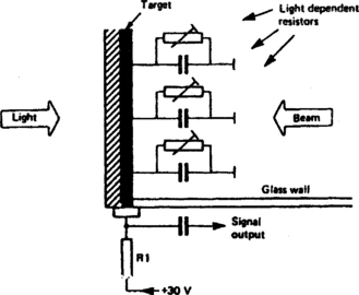
The photoconductive pick-up tube responds basically to the brightness (luminance) component of incoming light, and provided that the tube is reasonably panchromatic (sensitive to all colours) in its response the target’s output signal is suitable, after amplification and insertion of sync pulses, for r.f. modulation or direct feed to a video monitor. To produce a colour picture more information must be generated by the image sensor – enough in fact to give details of the nature of all three of the primary colours, red, green and blue at every single picture element. Techniques have been developed to achieve this with a single photoconductive tube, involving some form of matrixed faceplate. One variant is the colour striped faceplate drawn in Fig. 5.16.

Fig. 5.16 One form of single-tube colour-striping system. The stripes cover the outer glass faceplate, and are made of translucent gelatin-type material
In this form of striped faceplate the outer surface of the vidicon’s front glass is covered with vertical stripes of translucent colour filters in the form green, cyan, clear, green, cyan, clear, and so on. The green filter will permit only the green (G) component of incoming light to pass; the adjacent cyan filter lets through both blue (B) and green (G) components; the clear stripes, of course, pass all light allowing red (R), G and B to reach the vidicon’s photosensitive target. The basic video signal from the tube’s target electrode produces a luminance signal, since the image being scanned still contains all brightness information for the scene being televised. Because of the presence of the stripes, however, an extra signal will now appear at the target, modulated with information concerning the colours in the scene.
As the faceplate is scanned, each line of picture information contains ‘steps’ as shown at the bottom of Fig. 5.16. The first step contains the G signal, the second a B + G signal, and the third an R + B + G signal. If we subtract the G signal from the B + G signal we have a B signal. Subtraction of the B + G signal from the R + B + G signal renders an R signal. Thus by a simple matrix circuit we can derive the three primary colour signals (RGB) required for a colour TV system, ultimately for the three guns of a shadowmask picture tube. While this simple explanation proves that three primary colours can be derived from a stripe-filter using only two colours, green and cyan, the way in which the chroma signal is derived and processed in a practical camera is different, making full use of the luminance signal produced at the target: these techniques will be described in the next chapter.
The pitch of the stripes in the colour filter is in the region of 40 um, so the vidicon’s beam focusing requirements are very stringent. As soon as the beam diameter exceeds the stripe width all colour is lost, and deterioration of beam focus will remove the colour (and in some cameras, substitute an overall green cast to the picture) long before any loss of fine detail (luminance response) is discernible.
Fine detail in the picture being televised would cause a ‘beat’ pattern against the colour stripe gratings, so an optical filter (crystal filter) is present in the light path to remove it. This is one reason why very expensive lens systems are wasted on this type of camera. Because most types of vidicon tube – and particularly the Newvicon – are sensitive to infra-red radiation, an IR filter is also fitted: without this the colour rendering of an object would depend on its temperature as well as its natural colour.
SOLID-STATE IMAGE SENSORS
Semiconductor-type image sensors are rugged and compact, with indefinite life and an ability to withstand mechanical shock and huge overloads of incident light – a direct view of the sun would write off any vidicon-type tube except the silicon-target variant, whereas a solid-state sensor would be unaffected.
In this ‘flat-plate’ system the photosensitive surface is not continuous; it is divided into hundreds of thousands of separate ‘islands’ of silicon photodiodes arranged in horizontal rows to conform with the television scanning lines themselves.
Each photodiode consists of a single picture element, and during the 20 ms field period it builds up a voltage charge proportional to the light falling on it. Each photodiode cathode has its own MOS-FET transistor switch, as shown in Fig. 5.17. When a pulse is applied to the transistor gate the diode’s charge is transferred to a shift register. Unlike a digital shift register the type used in a solid-state image sensor can deal with an analogue signal which in effect consists of ‘packets’ of electrons. It is known as a bucket-brigade device (BBD) and finds applications elsewhere in consumer electronics, primarily for analogue delay lines.
The charge packets are stepped along the register by sequentially changing the voltages applied to the BBD’s cells. The electron charges readily fall into an adjacent ‘potential well’, and by setting up progressively deeper depletion layers in adjacent cells they can be stepped along the shift register/BBD by means of clock pulses in a four-phase sequence.
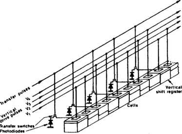
Fig. 5.18 represents a complete CCD photosensor; each column of photodiodes has its own vertical shift register. During each field blanking period a transfer pulse is applied to the gate of each FET to switch the charges accumulated in each photodiode into the adjacent shift register. All the FETs are simultaneously pulsed, so that once per TV field a complete set of pixel charges is transferred.
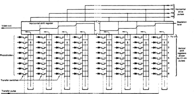
Fig. 5.18 CCD image-sensor array, showing ‘stepping’ characteristic of charge packets. This simple representation has 8 × 8 = 64 pixels, while practical sensors have hundreds of thousands
On the first change of V-clock pulse the charges in all the vertical shift registers hop one cell upwards. At the top of the array is a horizontal shift register, into which is now loaded the topmost line of the picture. This is another BBD, whose contents are continually and rapidly transferred towards the left by the same ‘progressive well’ technique as used in the vertical shift registers, using the same four-phase sequence of transfer pulses. For this register the pulse rate is much faster: the readthrough here is at picture-element rate, in practice about 8 MHz. The charge packets roll off the left-hand end of the horizontal shift register in the form of a series of pulses of varying height: an analogue video signal. Before it can be used the clock pulses and switching hash must be filtered out.
At each line blanking interval the vertical registers are pulsed to transfer complete picture lines into the horizontal BBD at 64 μs intervals, where each is clocked leftwards during the next line scan period. The serial information stream corresponds to the target output of a conventional vidicon tube. At the end of each field the charges from all the photodiodes have been read out, the vertical and horizontal BBDs are empty, and the whole sequence is repeated for the next field.
The CCD clock and drive pulses are generated in a timing/divider IC governed by the camera’s master sync and subcarrier generator section (SSG), which is itself paced by a precision crystal.
Colour CCDs
The CCD image sensor described above produces a monochrome picture; each photodiode’s charge is proportional to the luminance value of the pixel it represents. As with tubes, high-quality broadcast and professional cameras use three sensors, one for each primary colour, and the incoming light path is optically split and filtered. For consumer cameras this approach is very expensive, so single-array colour CCD image sensors have been developed with colour-filter matrices bonded to the faceplate and aligned with the photocell array. They work on similar principles to the ones described in this chapter (Figs 5.12 and 5.16) and the next.
Fast shutter
Like vidicon tubes, the CCD array builds up a charge throughout the field period, with each pixel integrating the light falling on it for about 19 ms. The storage effect of this exposure time gives good sensitivity, particularly important in low-light conditions. If, however, anything in the picture moves appreciably during this 19 ms period, it is displayed (during still-frame reproduction) as a blur. With a CCD image sensor it is possible to separate the ‘scanning’ and ‘storage’ functions to give a fast shutter effect.
Towards the end of the field period a special transfer pulse is applied to dump the photodiodes’ charges into the vertical shift registers. It is shortly followed by a high-speed pulse train through all the vertical registers to ‘flush’ them. The effect of this is not visible because the video signal is muted at this time: the process takes place during the vertical blanking period. A short period (set by the user’s shutter speed control) is afforded to the photodiodes to charge from incoming light, then once more a transfer pulse is applied to pass the charges into the vertical shift register. The brightness information acquired during this limited exposure is stepped along the registers in the normal way to form the video output signal, which appears continuous because of the storage capability of the cells in the BBD shift registers.
The penalty for fast-shutter operation, as with conventional photography, is a loss of sensitivity, calling for an increase in light level or a large aperture setting. A range of shutter speeds is provided to trade off sensitivity against blur effects, the fastest of which is only suitable for use in bright outdoor situations. Even in good light, however, fast shutter settings should only be used when freeze-frame or slow-motion analysis of the event is likely to be needed.