SURROUND-SOUND AND HOME CINEMA
As entertainment media, TV and the cinema have evolved in very different ways. Cinemas have long been regarded as superior to television in terms of sound and picture quality and ambience. The latter is enhanced by the fact that everybody in the audience wants to see the film, having paid to do so; and by having the place in darkness, with nothing to distract the viewer from the picture and sound. Many enthusiasts seek to recreate all these conditions at home now that the systems, media and hardware exist for it; or at least to get as close an approach as possible to the true cinema experience.
35 mm and 70 mm film, optically projected onto a large reflective screen, and viewed under the right circumstances, offers a picture quality and definition way beyond what is possible with current broadcast TV systems, together with a more natural aspect ratio (picture width/height proportion) than was available to TV viewers until the advent of widescreen TV sets and broadcasts. Although compromises with ‘letterbox’ picture transmissions are made, the results are far from satisfactory.
TV/VIDEO SOUND
The television sound system was for many years a ‘poor relation’ to the picture. All that was available, a single-channel (monophonic) signal, had restricted frequency response, and limited dynamic range and signal/noise ratio. Very often TV sets (even large-screen ones) were fitted with small loudspeakers and barely adequate audio amplifiers.
The first turning point came in the mid-1980s with Hi-Fi sound videocassette recorders. As explained in Chapter 17, their audio performance was far better than any other TV sound system, approaching that of audio Compact Disc. At that time, however, the only source media which could do justice to a Hi-Fi VCR was a pre-recorded (generally ‘movie’) tape cassette, and – because few TV sets were up to the job of reproducing the sound – it was often necessary to hook the VCR to a separate stereo amplifier to reap the full sound benefit.
Next came the Nicam transmission system described in Chapter 9; its abilities are reasonably matched to those of analogue Hi-Fi video recorders, and it became possible to record and reproduce good quality stereo sound, with Nicam decoders built into video recorders as well as large-screen TV sets. TV design, meanwhile, had evolved on the audio side so that there were now powerful inbuilt sound amplifiers; bass and treble controls; and the best loudspeaker systems it was possible to get into a plastic TV cabinet dominated by its magnetically sensitive picture-tube! Provision was also made, in most cases, for the connection of external stereo speakers.
CINEMA SOUND
Film sound is much more than dialogue, music and song. It conveys mood, ‘atmosphere’ and effects, all of which are a vital part of the whole presentation, and with large loudspeakers and powerful amplifiers cinema sound has a great deal more presence than its TV counterpart. The cinema industry latched on to stereo and multi-channel systems very early on, starting in the 1930s to build a soundfield which matched the size and depth of its moving pictures. By the 1950s 35 mm film prints carried at least a stereo soundtrack, and 70 mm prints typically had six separate sound strips for multi-channel reproduction via loudspeakers spaced around the viewing area. Magnetic-stripe soundtracks, while giving good performance, gave way to optical soundtracks because of the latter’s ease of duplication with the picture, and its cost and maintenance advantages in individual cinemas.
DOLBY SURROUND CONCEPT
The Dolby surround-sound system has its origins in the cinema industry, the original concept being to create a complete surround soundfield from an optically recorded stereo sound stripe-pair on film. Thus compatibility with mono and stereo equipment could be maintained. For mono reproduction the L and R signals are merely added together, and for stereo each is reproduced via its own amplifier and speaker, one on each side of the screen. For the surround effect, the left- and right-channel signals are applied to a decoder from which emerge the audio feeds for the several loudspeakers involved.
Four channels are used to create the surround effect: Left, Right, Centre, and a fourth called Surround. Left and Right emulate the normal front stereo sounds, while the front centre channel is there to anchor ‘on-screen’ sound, particularly speech and dialogue, to the screen area: this is specially important for viewers on the sides of the listening area. The Surround channel, by contrast, is used to create an ambience or atmosphere behind and around the viewer, and to enhance such effects as thunder, crowd scenes and aircraft flying overhead. In practical home systems the surround signal is generally fed to two speakers at the rear of the viewing room with a time delay, as we shall shortly see. Fig. 21.1 shows the loudspeaker placement in a typical domestic environment, in which the larger the TV screen the more effective is the overall effect.

Fig. 21.1 Speaker positioning for fully specified surround-sound reproduction. The (optional) woofer can be placed anywhere in the room
Since the whole soundfield, in four separate signal streams, has to be carried in just two channels the possibility of crosstalk is there. Some degree of crosstalk among the three front channels is tolerable because the sounds they make are all coming from the general area of the screen. It is important to minimise crosstalk between the centre and surround channels because any significant signal-leakage here would have the effect of dispersing the sound of speech and dialogue in the viewing area and thwarting the ‘tight-targeting’ purpose of the centre channel. To maximise front/back signal separation, time-delay and bandwidth-restriction techniques are used. The rear-channel signal is electrically delayed by a period longer than the acoustic soundwave takes to traverse the room in order that the dialogue is heard first from the front; and the limited bandwidth of rear/surround sound minimises the effects of crosstalk and reduces the perceived directionality of sounds coming from the side and/or rear speakers.
Because the Dolby Surround system depends on phasing of signals in the two transmission or ‘storage’ channels it is vital that they are closely balanced in terms of gain, bandwidth, delay and propagation time.
Surround encoder
Fig. 21.2 shows the basic principle of Dolby Surround encoding. The encoder accepts four separate inputs and generates from them two signals, left-total (Lt) and right-total (Rt). The L and R input signals go directly to the Lt and Rt outputs without modification in order to maintain full stereo compatibility. The C (centre) channel input – having undergone a 3 dB level reduction to achieve constant acoustic power in the mix – is simply added to both L and R on their way through. The S (surround) signal is also added to each of L and R, but it first undergoes some special processing. Its frequency spectrum is limited to the range 100 Hz–7 kHz in a bandpass filter, after which it undergoes a noise-reduction process similar to that used in the Dolby B NR system. Finally, plus and minus 90° phase shifts are given to the S signal before its addition to L and R signals respectively, so that there is 180° phase difference (in effect an inversion) of the S signal between Lt and Rt feeds.
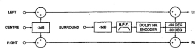
Study of the diagram shows that the L and R signals remain independent throughout: there is no crosstalk. Neither is there any crosstalk between centre and surround signals because while the S signal is formed out of the difference between Rt and Lt, the C components in them are identical, and thus cancel out. The centre channel signal is derived from the sum of Lt and Rt, and this sum is immune to the effect of S signals: being equal and opposite they cancel out in the centre output. It is now plain why the two channels carrying Lt and Rt must be closely matched in terms of amplitude and propagation delay. Any shortcoming here introduces crosstalk between C and S channels, and a corresponding loss of realism in the reproduced soundfield.
DOLBY DECODERS
A simple passive decoder, in effect the inverse of the block diagram of Fig. 21.2, can be used to give a surround effect. It is based on a simple L-R difference amplifier. The centre signal is reproduced in ‘phantom’ form between the L and R main speakers. The surround signal is also present in the L and R speakers, but out of phase between them, and thus diffused. Although this form of passive decoder is capable of good signal separation (greater than 40 dB between S and C, and L and R channels) it is not used; decoding is carried out in an active system called Pro-Logic, for which purpose-designed IC packages are available. Before we examine this it is worth looking into the purpose and effect of the blocks in the S-signal processing chain of the encoder in Fig. 21.2, and in the decoder used in the receiving or playback equipment.
While crosstalk between front and rear channels is tolerable to some degree, its effects are minimised as far as possible: in the electrical system, in the acoustic link, and in the listener’s ear and brain. The 7 kHz filter has two main benefits: in the presence of azimuth error between the two main channels, crosstalk increases with signal frequency, and reducing h.f. content in the S channel mitigates its effect. Secondly (and less important in the home than in the cinema) the suppression of high frequencies and thus transients in the rear loudspeakers has the effect of making them sound more distant and their sound more diffused, important to viewers who are not seated near front centre of the viewing area. The noise-reduction system, apart from its usual function of reducing hiss and noise, helps to reduce front channel signal leakage, though the amount of NR processing is limited by the need to preserve the nature of the L and R front-channel signals.
The time-delay inserted in the S-channel of the decoder is not there to provide any kind of echo or spatial effect, at least within the terms of reference of the decoding process, though in commercial equipment designs it is used to help simulate the acoustic effects of different types of building, and the ‘Hall’, ‘Theatre’, ‘Club’ and other settings provided are mainly dependent on changing attack/decay times and the delay period. The function of the delay in its Dolby decoder role is to sharpen and focus the front-channel sounds, and prevent them from being ‘fuzzed’ by rear-channel sound. The delay period is adjusted according to the distance between front and rear speakers in order to compensate for the propagation time of sound through the air, about 3 ms per metre; the Haas or precedence effect then ensures that the front-channel sound hits the listener before that from the rear/effects speakers. An adjustable delay range of 15–30 ms caters for all normal domestic situations.
Pro-Logic decoder
Fig. 21.3 represents the heart of a Dolby Pro-Logic decoder, an adaptive matrix. The Lt and Rt signals pass straight through for the L and R channels, and initially into a pair of bandpass filters to derive control signals for surround processing. The filters strip out low-frequency signal components, which convey no directional indications; and high-frequency components, whose phase and amplitude characteristics cannot be relied upon. Now the signals are sampled, amplitude-wise, in a series of full-wave rectifiers: one for Lt, one for Rt, one for Lt + Rt and one for Rt – Lt. The resulting d.c. voltages are log-converted and then compared to produce difference signals at points A and B. Each of them varies in amplitude and polarity according to the dominance axis of the soundfield from moment to moment. Control signal A, derived from L and R, indicates left/right dominance vector, while signal B conveys the front/rear dominance vector. For small dominance factors a relatively long time-constant is used in the following filters; when a large dominance factor is detected by the threshold switches, a shorter time constant is invoked. Now the control signals are resolved into positive and negative components in a pair of polarity splitters to produce four unipolar ‘steering’ voltages EL, ER, EC, and Es, each representing directional sound dominance. They are applied to a bank of eight VCAs (Voltage-Controlled Attenuators) through which the Lt and Rt signals are passing. The resulting eight outputs, together with the ‘pure’ Lt and Rt signals, now enter a combining network in which portions of the ten available signals are added or subtracted according to a characteristic weighting factor to produce left, right, centre and surround output signals in correct proportions, and always with a total acoustic power corresponding to the original ‘studio’ conditions.
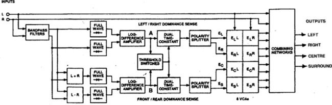
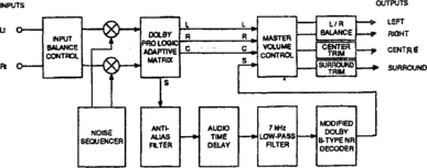
Fig. 21.4 shows the other main components of the Pro-Logic decoder. The noise sequencer is a local source of test signals for setting-up purposes, switched off during normal listening. The L, R and C signals from the adaptive matrix pass through volume-, balance- and trim-control stages on the way to their separate power amplifiers and loudspeakers. The surround signal undergoes conditioning before it is applied to these: first comes an anti-alias filter to prevent sampling errors in the following digital time-delay block, whose storage period is typically 20 ms. The 7 kHz low-pass filter next downstream has the main function of suppressing spurious switching spikes from the delay section and smoothing the output from its D-A converter. Finally comes the noise-reduction section, working in complement to the NR encoder of Fig. 21.2.
While the 100 Hz−7 kHz limitation on the surround signal fed to the rear speakers may appear restrictive, the facts that all the front speakers have full frequency response, and all the sound channels are allied, means that the overall effect is perfectly acceptable. It would be quite otherwise if the rear speakers were carrying a totally different programme signal – only then would any shortcoming become discernible. The same remarks apply to the separation/crosstalk characteristics of a Dolby Surround system, whose practical (as opposed to theoretical) signal-separation map is given in Fig. 21.5.
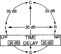
Fig. 21.5 Dolby signal-separation map for Pro-Logic system. The time-delay, low-pass filtering and noise reduction carried out on the signals coming from the rear speakers add to their perceived ‘separation from the front sound
An internal diagram of a dedicated Dolby Pro-Logic decoder chip is shown in Fig. 21.6. Lt and Rt signals enter the IC at pins 9 and 10, and L, R, C and S leave on pins 37, 36, 34 and 35 respectively. Pins 1–8, 15–21, and 22–28 of the IC in Fig. 21.6 are occupied only by capacitors which provide reservoirs and time-constants for the chip-internal circuits. This IC works in conjunction with a digital delay chip for rear/surround channel processing, filtering and effects.

Alternatively the whole Dolby Pro-Logic decoding process can be carried out in the digital realm, with an A–D converter working on the Lt/Rt signals at the input of the DPL processor chip, and D–A converters at each of the four outputs. This is common in late decoder designs.
Surround amplifiers and processors
Many large-screen TV sets have Dolby Pro-Logic decoders and amplifiers built into them, with output sockets for the rear speakers. It is difficult to provide the drive power and to accommodate suitable speakers within the confines of a TV cabinet, however, and a better alternative is a separate, dedicated surround decoder/amplifier: there is a wide range commercially available. They typically incorporate many stereo input sockets to cater for all the possible signal sources (Dolby surround sound can be conveyed by videotape, disc, terrestrial, satellite and cable transmissions in analogue or digital form); on-screen set-up, adjustment and indication by virtue of a character/graphics generator and Scart-to-TV hook-up; very often a radio tuner; a variety of effects and simulations of different buildings and venues; and so on. Output powers range up to many hundreds of watts.
SURROUND LOUDSPEAKERS
Five loudspeakers are generally used with a surround-sound outfit: left main, right main, centre and a rear pair for effects, of which the first two are the most important. The centre front speaker needs to be reasonably matched, in terms of frequency response and ‘timbre’, to the L and R main ones, and where it is to be placed near a direct-view TV or monitor screen it must have a low stray magnetic field to prevent interference with tube beam-landing and consequent impurity/colour-staining effects; suitable types are made and marketed to meet this need. All the loudspeakers must have impedance and power ratings suited to the amplifier with which they are used, and correct phasing of their feeds is very important. Amplifier and speaker terminals are coded red/black or +/–, and if any speaker(s) are incorrectly phased very strange effects can result.
Subwoofer
Low audio frequencies have virtually no directionality, and so it is not necessary to have more than one powerful subwoofer unit to reproduce the bass: so long as it is present somewhere in the listening area the viewer is satisfied that the entire system is reproducing it, and perceives that the centre speaker is larger than it actually is! Surround decoders have an output terminal for a subwoofer, then, generally carrying a line-level signal for application to an ‘active’ (incorporating its own power-drive amplifier) type which can be positioned anywhere in the room – its effect is felt as well as heard.
‘Phantom’ centre sound
In domestic situations with a small audience and good seating positions the centre channel is less important than in a large cinema where some viewers may be dominated by a left, right or surround/effects loudspeaker. In home systems, then, the centre loudspeaker can be left out, and its signal simulated by the in-phase operation of L and R main speakers.
ALTERNATIVE SURROUND SYSTEMS
The passage of time and the advent of digital transmission and storage media for TV has introduced new systems of conveying surround sound. THX is an enhanced variant of Dolby Pro-Logic processing requiring its own software, decoder and speaker system. AC-3, now known as Dolby Digital, has five separate channels of audio: left, right, centre, left rear and right rear, plus a dedicated subwoofer channel. It gives tighter ‘targeting’ of the soundfield, and can offer completely separate signals in the two rear channels. First available from NTSC laser discs and DVDs, it depends on the more generous capacity of digital media. Similar in this respect is the MPEG2-audio/5.1 audio standard.
HOME CINEMA
The main components of a home cinema set-up are a large viewing screen and a surround-sound system. The screen may be a direct-view or projection type of the sorts described in Chapter 5, with large widescreen and projection types favoured best. Signal sources, as well as terrestrial and satellite broadcasts, are videotape (whose drawback is that movies are only available in relatively low-quality standard-VHS format) and video disc, laser or DVD type. The latter gives best possible sound and vision reproduction, especially with a wide screen and a good audio system because it is the only domestic recording medium which is designed for widescreen and surround sound, without compromises.
Other ‘widescreen’ TV picture sources, excepting true 16:9 aspect-ratio digital broadcasts, really consist of ‘letterbox’ pictures, in which a standard 4:3 aspect-ratio system is used, with black bands above and below the picture. It has the disadvantages of wasting up to a third of the available screen area on a conventional picture tube, and of impairing the vertical definition on a wide screen, because the vertical scan amplitude has to be increased to fit the picture to the screen; the result is a coarse line structure. Cinema films recorded on VHS videotape are likewise in letterbox format, and the same limitations apply. Those VHS videorecorders sold with ‘widescreen compatibility’ have no special format or processing features beyond an ability to detect an on-tape flag and pass it to the TV as a midpoint voltage (6–8 V) at Scart pin 8: a suitably equipped widescreen TV or monitor auto-switches to widescreen scanning on receipt of this. The way in which 4:3 aspect-ratio pictures are adapted to wide screens was shown on page 213.