
AERIALS AND RECEIVERS
For the purpose of this chapter we shall regard a receiver as that section of a TV or videorecorder installation concerned with the selection, tuning, filtering, amplification and demodulation of transmitted TV signals, culminating in the deliverance of the standard 1 V video waveform, and a 0 dB (0.775 V r.m.s.) baseband audio signal.
AERIALS
The first and one of the most critical links in the receiving chain is the aerial. In effect it forms the first tuned circuit of many, and its performance is crucial to the recording and display of good pictures. The basic pick-up element is the dipole, consisting in practice of a metal rod, divided at its centre by an air gap of about 20 mm for connection to the transmission line. Its overall length is approximately half that of the wavelength on which optimum reception is required. The impedance at the centre is approximately 72 Ω, a reasonable match to the 75 Ω coaxial cable used to link the dipole to the r.f. input of the tuner, whose characteristic input impedance is likewise 75 Ω. Normally the centre conductor of the coaxial cable is connected to the upper half of the dipole and the outer (screening) braid to the lower half.
Parasitic elements
The basic half-wave dipole is omnidirectional, and this can be a disadvantage in terms of susceptibility to interference and the pick-up of unwanted signals. To overcome this, and to add some useful gain, further elements are usually fitted. The H-type aerial, much used on VHF band I, consists of a half-wave dipole and a reflector: a second and slightly longer metal rod. The reflector is mounted one-quarter or one-eighth of a wavelength behind the dipole. It has no electrical connection with the dipole, but influences the dipole impedance and its directivity. By reflecting an in-phase signal back to the dipole an improvement in gain of some 3 dB is made by the reflector for signals in the ‘forward’ direction, while signals arriving from the rear are attenuated; a front-to-back ratio of 9 dB is typical of an H-type aerial. See Fig. 3.1 for an explanation of dB ratios, and Table 24.4 for conversions.
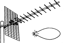
Further gain and directivity can be gained by adding directors in front of the dipole. They have the effect of concentrating the signal on the dipole element, and up to sixteen may be fitted to high-gain aerials in a Yagi configuration, Fig. 3.2. Here the reflector takes the form of a mesh or grid for high gain and good back-to-front ratio. The dipole is a folded type for greater bandwidth and better impedance matching to the coaxial feeder; the presence of parasitic elements tends to reduce dipole impedance. The polar diagram in Fig. 3.2 gives an idea of the directive properties of the multi-element Yagi aerial.
Grid and log-periodic aerials
For use in areas of high signal strength the grid aerial is neater and more compact, consisting of a grid or mesh reflector mounted behind one or more folded dipole collectors, typically in a bow-tie shape. It offers great discrimination against signals arriving from the rear.
A log-periodic aerial has a series of dipoles, graduated in length (and thus resonant frequency) mounted along a dual boom which also acts as a transmission line to carry the signal to the downlead feeder. Its characteristics are relatively low gain, great bandwidth and freedom from side-lobes in its polar response. It does not have the directivity of a Yagi type, and is the least common configuration in domestic reception.
Bandwidth
As a ‘tuned circuit’ a receiving aerial has a certain bandwidth, determined by its physical characteristics. For reception from UHF transmitting sites in the UK an aerial bandwidth sufficient to cover all four or five local channels is required; with few exceptions the signals from each BBC/ITV site fall within one of the aerial groupings given in Table 2.7. Things can be far otherwise with Channel 5 as Fig. 2.8 and Table 2.8 show.
FEEDERS
The transmission line between aerial and tuner is an important component. For minimum loss, thick coaxial cable should be used: semi-air-spaced coaxial cable is best, though cellular-polythene spaced types are a good compromise between performance and cost in areas of good signals and where the cable run is not too long. The performance of the feeder (and other distribution components like amplifiers) is particularly critical where teletext receivers are in use. Short-term reflections due to poor cable routeing and mismatch at terminations and connections will upset text reception and lead to the display of blanks and errors in the characters and graphics.
DISTRIBUTION AMPLIFIERS FOR UHF
Apart from MATV installations in blocks of flats, hotels and shops, there is an increasing demand for multiple aerial outlet points in ordinary dwellings, where several TV sets may be found in different rooms, often requiring signal feeds from VCRs and satellite receivers as well as off-air transmissions. For this purpose a simple mains-powered distribution amplifier is used, mounted at the rear of the main TV, or (to save difficult cable-routeing and redecoration problems) in the loft or even on the aerial pole itself. From here separate cables are routed to up to six outlets in different rooms. In areas of good field strength a passive splitter may be used to provide two outlets from a single cable, but at least 6 dB attenuation is introduced in each path.
SATELLITE AERIALS
At microwave frequencies a form of dipole (in fact a probe) is still used for signal pick-up, but unaided it would intercept virtually none of the very low-level signals from space. Even the addition of parasitic elements in Yagi form would not be effective – the signal capture area would not be great enough. Instead a parabolic dish is used to intercept r.f. energy over a larger area. The surface of the dish is carefully formed into a true uniform parabola so that the centimetric waves are all reflected, uniformly and in phase, to the focal point. Here may be mounted the pick-up probe, though sometimes a subreflector is fitted to redirect the energy to the centre-point of the dish, where sits a waveguide in which the pick-up probe is mounted. The difficulties of conveying SHF signals is such that a low-noise amplifier or mixer stage is connected direct to the pick-up probe itself – more on this in Chapter 4.
TUNERS
The UHF tuner has several functions. It has to reject out-of-band transmissions, amplify the incoming signal and then mix it with an internally generated c.w. (continuous-wave) signal to give an output on the difference frequency between the two UHF signals – the incoming a.m. modulated one and the local oscillator output. The tuner’s local oscillator runs (for UK receivers) at a frequency 39.5 MHz above the required vision carrier frequency, so that for instance in the case of channel 23 (Fig. 2.6(a)) whose vision carrier has a frequency of 487.25 MHz the local oscillator would need to run at precisely 526.75 MHz. The two signals come together in a mixer, a non-linear device which produces outputs at the sum and difference frequencies of its two inputs. In this case the difference frequency of 39.5 MHz (i.f., intermediate frequency) is selected by a tuned-circuit filter which rejects other frequencies. This filter and subsequent circuits have a bandwidth sufficient to embrace not only the sideband signals corresponding to high frequencies in the vision signal, but also the sound i.f. which will appear at 33.5 MHz. This arises from the difference between the channel 23 sound carrier at 493.25 MHz and the same local oscillator frequency of 526.75 MHz. What has been described is in fact the superheterodyne principle, which is used in virtually all r.f. receiving equipment from pocket radios up to satellite installations.
The great virtue of superhet operation is that by altering the local oscillator frequency any required incoming signal can be translated to a single, common frequency carrier – the i.f. Provided the local oscillator is made to run at a frequency (in this case) 39.5 MHz higher than the wanted one, the signal (complete with sidebands) is translated to a single low frequency where it can be dealt with by a fix-tuned amplifier with fix-tuned filters to shape the required passband. Thus the need for ‘movable’ tuned circuits is confined to three or four within the tuner itself.
Apart from offering gain to overcome the inherently noisy mixing process, and isolating the local oscillator signal from the aerial, the r.f. amplifier is required to reject the image frequency. At a given local oscillator rate (fosc) there are two input frequencies which can give rise to a 39.5 kHz i.f. signal – the wanted frequency at fosc – 39.5 MHz; and an unwanted (image) frequency at fosc + 39.5 MHz. The bandwidth of the tuned r.f. amplifier (generally a two-stage section) is tailored to offer approaching 60 dB of image frequency rejection at a frequency 79 MHz above the wanted carrier. Calculation shows that the sound carrier of channel n + 4 (where n is the required channel) will give rise to a spurious i.f. signal 1.5 MHz away from the required vision i.f. carrier. To avoid beat pattern effects on the picture the r.f. amplifier’s response to the n + 4 channel must be at least 55 dB down.
On VHF bands I and III, conventional inductors and capacitors can be used in the tuned circuits required for oscillator and r.f. amplifier tuning. On UHF bands IV and V such inductors would consist of less than one turn, and designing a tuner along such lines would be difficult. An alternative technique is the use of distributed constants in tuned circuits making use of lecher lines printed on the surface of a low-loss insulating board. Each line is equivalent in length to an electrical half-wavelength, having one end grounded and the other end (nodal point) tuned by a variable capacitor with which its resonant frequency can be swung over the required range.
Fig. 3.3 shows a typical varicap tuner’s circuit diagram. For optimum noise performance and matching over the entire UHF band 470 to 860 MHz the input circuit is untuned. TR701 forms the first r.f. amplifier and operates in grounded-base mode, with the input signal applied to the emitter via the diode attenuator D600/D601. TR701 collector circuit incorporates a tuned load L510 whence the signal is transferred via C213 to bandpass tuned circuit L511/L512. The local oscillator is TR702, whose frequency is governed by the capacitive loading at the top end of lecher line L518. Local and broadcast signals are applied via C220 and L513 respectively to Schottky mixer diode D603. At its anode appears the wanted beat signal, selected and filtered by the LC network en route to i.f. amplifier TR703, again a common-base stage. TR703 collector circuit is returned to ground externally of the tuner, and further selection and filtering takes place in L523 and associated components.

AGC is applied in two ways in this tuner. The attenuation offered by the PIN diode pair D600/601 depends on the amount of current ‘sinked’ from the gain control pin 3 by the external a.g.c. control circuit; at high current levels (9 mA) D601 is fully on and D600 off so that the full signal level is applied to TR701 emitter. As the a.g.c. current decreases D601 turns off and D600 becomes progressively more conductive, attenuating the UHF input signal. The very linear attenuator so formed offers excellent performance in the face of high levels of unwanted signal, thus very good cross-modulation performance.
VARICAP TUNING
Traditionally a variable capacitor is a mechanical device in which interleaving vanes are rotated by a shaft, their degree of mesh determining the total capacitance. The same effect can be achieved by the use of a varicap diode, the junction capacitance of which can be varied between typically 20 pF and 2 pF for applied reverse-bias voltages between 1 V and 28 V. The three varicap diodes in the tuner of Fig. 3.3, D605, D606 and D607, are carefully matched and selected in manufacture to have identical voltage/capacitance curves. The two bandpass tuned circuits L510/L511–12 in the r.f. stage are thus tuned exactly in step, and the oscillator frequency maintained exactly 39.5 MHz higher in frequency – a process known as tracking. Correct tracking ensures optimum gain and performance throughout UHF bands IV and V. The channel selected, then, depends on the d.c. voltage applied to tuner pin 4.
Deriving the tuner control voltage
With received channel number depending purely on the d.c. voltage applied to the varicap tuner, a wide range of options is open to the TV set designer, including self-seeking systems, remote control and station memory, all based on modern IC technology. They will be examined later in this chapter and in Chapter 22. While the simplest types of monochrome receiver use a single rotary potentiometer as tuning control, in conjunction with a stabilised 30 V source, a slightly more sophisticated tuning system is used in inexpensive TV sets and videorecorders: Fig. 3.4 shows its basis.

A specially developed two-terminal chip, IC1, acts as a temperature-compensated voltage source for a series of potentiometers in a tuning bank. Each slider taps off a potential appropriate to one of the local TV transmissions, and is selected by a push-button, of which there may typically be eight, marked BBC 1, BBC 2, ITV, Channel 4 etc. The tuning voltage thus set passes into the varicap tuner, having had added to it an a.f.c. control voltage derived from the i.f carrier. The effect of the a.f.c. voltage is to correct for slight tuning errors by ‘pulling’ the local oscillator up or down to achieve an exact vision i.f. frequency of 39.5 MHz, when tuning is spot on. Because the influence of a.f.c. control can mask the correct tuning point, provision is often made to switch it off when manual tuning is carried out: the most common artifice is a switch operated by the flap or door which conceals the tuning potentiometers.
IF AMPLIFIERS
As with the tuner, the i.f. amplifier has several functions, not all of them immediately obvious. Its primary task is to amplify the tuner’s output signal to a level where it can be practically demodulated. It is also required to maintain a constant output signal level in the face of very wide variations in signal input level; to provide a closely defined passband, selectively amplifying wanted signals and rejecting adjacent ones; to furnish a.g.c. and a.f.c. control lines for the tuner; and to offer a reasonably linear phase response or group-delay characteristic, important for colour reproduction and crucial to good teletext reception.
Bandpass shaping
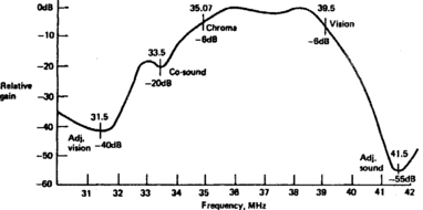
The tuner’s r.f. stage offers rejection of unwanted signals which are widely spaced from the carrier in use, but is not sufficiently selective to reject frequencies within a few MHz of it. Thus adjacent channel and other spurious signals emerge unscathed from the tuner and must be rejected in the i.f. stage. For use with a synchronous demodulator (see later) the required response curve is as shown in Fig. 3.5. Deep rejection notches are provided at 41.5 MHz (adjacent sound carrier) and 31.5 MHz (adjacent vision carrier), and a shallower one at 33.5 MHz, corresponding to the co-sound i.f. frequency. The need for the 33.5 MHz notch is twofold: to prevent a high level of sound carrier beating with the colour subcarrier at 35.07 MHz to produce a 1.57 MHz pattern on highly coloured areas of the picture; and to depress the sound carrier to a level where it remains below the minimum excursion of the vision signal (i.e. peak white) so that it will not become amplitude-modulated by picture frequencies to cause difficulties with buzz on sound.
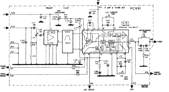
For many years conventional LC tuned circuits were used for filtering and bandshaping in i.f. circuits, which then typically consisted of a 3-stage transistor amplifier feeding a simple diode detector. TV and videorecorder receivers now use a SAW (Surface Acoustic Wave) filter for the purpose. An idea of its construction is given in Fig. 3.6. An input signal transducer converts the incoming electrical signal to an acoustic wave which is propagated across the surface of a piezoelectric substrate. Its ease of passage depends on the frequency involved – the design of the resonant transducers is such that the response curve of Fig. 3.5 is closely maintained. The most critical area is around the vision i.f. frequency of 39.5 MHz, where the output signal should be exactly 6 dB down from full gain, see Fig, 3.6(b). The use of a SAWF greatly simplifies the fabrication and setting up of the i.f. amplifier, as can be seen in the typical circuit of Fig. 3.7. Here the i.f. input signal is amplified by about 26 dB within IC50 before application to the SAWF, whose output passes direct to the balanced inputs of IC51.

Fig. 3.6 SAW filter: (a) basic construction; (b) tolerance-response curve must lie within the shaded area
Although this type of circuit has now been superseded by direct drive of the SAWF from the tuner and more comprehensive i.f. chips, it better illustrates the principles involved, particularly in the next section.
Amplification and detection
The TDA2540 chip IC51 contains amplifier, demodulator, a.g.c. and a.f.c. stages, together with some noise-reducing circuitry. The level of the recovered video signal is sampled in the a.g.c. detector, which regulates the amplifier gain to maintain constant output level. Normally the UHF tuner is kept at full gain to minimise noise, but when the TDA2540 chip is turned fully down (at an r.f. input level of around 5 mV) control over the tuner gain takes place via IC pin 4. The onset of r.f. a.g.c. is governed by the crossover control VR36. L36 is associated with the vision demodulator and is tuned with C45 to the vision i.f. of 39.5 MHz. If the i.f. frequency increases, the potential at IC pin 5 reduces and vice versa, and this is fed back to the tuner’s tuning voltage input to form an a.f.c. loop; a defeat line is provided at IC pin 6 whereby the a.f.c. action can be cancelled when fine-tuning or changing channels. With the a.f.c. on, L36 is adjusted for correct tuning, thereafter compensating for ageing and thermal drift in the tuner’s local oscillator, or for carrier drift in any local r.f. signal source.
The demodulator works on the synchronous principle. A sample of carrier signal is amplified, clipped and applied to the ‘tank’ tuned circuit L34/C43. The result is a train of sampling pulses at 39.5 MHz, and these are used to gate the amplitude-modulated vision i.f. signal, taking a sample of its level on each carrier cycle. The succession of these samples forms the demodulated vision signal. The synchronous demodulator is capable of linear operation and has good intermodulation performance.
The video signal is preamplified within the chip, whence it emerges on pin 12. At this point it carries a 6 MHz intercarrier sound signal – the product of the 33.5 MHz sound i.f. signal – which is removed from the video signal by bridged-T notch filter L32/C39/C40/R34. At point 4/8 in the diagram, then, appears the 1 V pk-pk CVBS signal in the form shown in Fig. 2.5.
All these principles are embodied in the multi-purpose ICs now used in receivers and in the integrated tuner/receiver modules often fitted to TVs and videorecorders.
SOUND DEMODULATION
Since the deviation of the sound carrier (now in 6 MHz form) is ±50 kHz, a sharply tuned circuit with at least 100 kHz bandwidth, and centred on 6 MHz, is required to filter out the sound carrier from the video waveform. It takes the form of a ceramic filter, a very small mechanical resonator with sharp cut-off characteristics. After passing through one or two of these the sound carrier is ‘clean’ and ready for delivery to its demodulator. First (Figure 3.8) it passes through several limiter stages, in which it is repeatedly amplified and clipped to remove all traces of amplitude modulation, and with them the influence of interference spikes and noise. The sound detector is also a synchronous type, but here working in quadrature mode, with the 6 MHz tank coil L1 adjusted so that the carrier-sampling pulses are 90° out of phase with the cycles of the unmodulated carrier. The output from this arrangement is proportional to phase angle of the sound carrier, which is what is required for f.m. demodulation. A preamplifier within the IC brings the level up to the 0 dB (0.775 V r.m.s.) point, or indeed any other required level; its gain is adjustable in many chip designs by virtue of an internal voltage-controlled attenuator (VCA). By this means sound level can be controlled by application of a variable d.c. voltage, useful for local control and muting purposes and essential for remote control applications. In Fig. 3.8 the VCA is controlled via pin 8 of the chip.

Fig. 3.8 Sound IF and detector circuit by SGS-A tes. This one also incorporates a power output stage with feedback, forming the entire sound section of a TV receiver in one IC package
The sound limiting, demodulator and initial amplifier stages are often incorporated in the same IC as the vision section shown in Fig. 3.7, together with many other functions. Again the dedicated chip shown here gives a better insight into the principles involved.
FREQUENCY-SYNTHESIS TUNING
Since the received channel depends purely on the frequency of the local oscillator within the tuner, and since broadcast transmissions – be they from terrestrial or space-based transmitters – are held very accurately to their nominal frequencies, there is no theoretical need for any trial-and-error tuning systems. Very accurate and stable crystal control of the receiver’s local oscillator would suffice for a fixed-tuning system. In practical frequency-synthesis tuning systems the ‘analogue’ oscillator is still present within the tuner, and still controlled by a d.c. potential acting on an array of varicap diodes. Here, however, the oscillator is made part of a phase-lock-loop (PLL) in which it comes under the influence of a stable local frequency reference in the form of a quartz crystal.
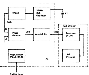
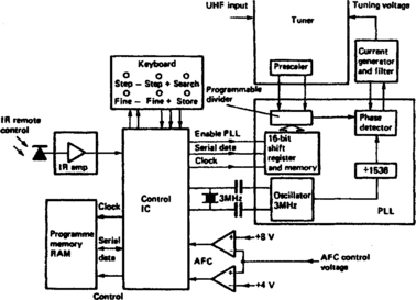
A basic block diagram is given in Fig. 3.9. Inside or adjacent to the tuner is a prescaler which divides the local oscillator frequency fosc by 64, and is capable of working with input frequencies up to 1 GHz (1000 MHz). The counted-down frequency is fosc/64, and this is applied to an LSI (Large Scale Integration) digital IC called a programmable divider which further divides fosc/64 by a factor determined by its programming instructions. Their derivation will be described shortly. Thus at the phase detector’s ‘A’ input appears a signal frequency which depends on (a) the tuner’s local oscillator frequency, and (b) the division ratio of the programmable divider. At the top of the diagram appears a reference crystal oscillator running at 3 MHz and feeding a fixed divider (counter) whose division ratio is fixed at 1536. 3 MHz divided by 1536 is 1.953 kHz and this is the frequency applied to the ‘B’ input of the phase detector. Whenever the frequency or phase of the A and B inputs differ the phase detector produces a d.c. error output whose polarity is dependent on the direction of the error (i.e. whether B input is faster or slower than A input); and whose magnitude is proportional to the difference in speeds between the two inputs. The error voltage is amplified and filtered and appears as a control potential on the tuner’s varicap control line. Since the local oscillator is in effect a VCO (Voltage-Controlled Oscillator) its frequency changes until the two inputs of the phase detector come into frequency and phase coincidence, when the varicap control potential stabilises. What we have set up is a phase-lock-loop (PLL) in which fosc is locked to a multiple of the 3 MHz crystal reference, the exact multiple being set by the division ratio of the programmable divider (PD) block. In fact the PD can divide by numbers between 256 and 8191.
To set a required channel, then, we merely give the divider a coded instruction to correspond with the known and preprogrammed channel frequency. We know that the local oscillator must run 39.5 MHz above incoming r.f. and we know the CCIR standard vision carrier frequencies for each TV channel. Taking a numerical example, suppose it is required to tune channel 41 whose vision carrier is 631.25 MHz. Required tuner fosc is 631.25 + 39.5 = 670.75 MHz, giving rise to 10.48 MHz from the prescaler. To satisfy the 1.953 kHz input requirement of the phase detector we need to set a division ratio in the PD of the 10480/1.953 = 5366. This ratio is one of, say, 100 available to cover all CCIR-approved TV channels on the four bands available to terrestrial transmissions. Each channel instruction is held in a ROM (read-only memory) as a group of thirteen binary digits (bits), and for the channel 41 division ratio of 5366 the binary code happens to be 1010011110001. For UHF channel 64 the division ratio is 6838 and the corresponding binary code 1101010110001.
The ROM needs in this case to have 100 memory addresses with the appropriate code for the division ratio for each possible channel permanently stored there. Thus (in simple terms) if channel 41 is requested on the user’s keypad, address no. 41 will be accessed and its contents 1010011110001 read out into the instruction register of the programmable divider. Some of the digits contain bandswitching instructions (not currently needed in the UK except for a satellite receiver option) which are decoded and passed to the tuner(s) to enable the appropriate section to operate.
Most frequency-synthesis tuning systems have facilities for sweep-search. An alternative name for it is self-seek, and when this function is invoked the control system steps through the 100 addresses in the programme ROM sequentially, presenting their contents in turn to the programmable divider. The tuner is thus stepped through all available transmission channels in its search for a broadcast transmission. When one is found the TV’s line oscillator quickly synchronises to it: an output pin on the line generator chip signals ‘locked’ to the tuning control microcomputer, instructing it to stop seeking. What happens next depends on the user’s requirements. If he wishes the set to memorise that channel, a touch of the ‘memory’ button will write the PD instructions into a RAM (Random Access Memory) for instant call-up when that channel is next required. These binary-coded instructions may typically be held at ‘Address 1’ in the RAM and contain data corresponding to the local BBC 1 transmission channel. Further seeking will find the other local channels and the output channels of other equipment like videorecorders, TV games and home computers, and each can be assigned to memory in turn. This memory store (EEPROM, Electrically Erasable Programmable Read-Only Memory) is built in ‘floating gate technology’ which means that the data is held in the form of electrostatic charges in the isolated gate regions of an array of FETs (Field Effect Transistors). Such a memory is called non-volatile because the data can be held for several years without any need for external power. This type of memory is ideal for TV channel data storage in a set which may not be continuously powered. In fact the contents can be erased and overwritten by means of applying a high ‘erase voltage’ of +33 V, and this is carried out whenever the user or installer re-programmes the memory.
A basic block diagram of the synthesis control system is given in Fig. 3.10. The need for a.f.c. control may well be questioned in view of the accuracy and stability of the crystal reference. In fact none is needed for broadcast transmissions, but the r.f. modulators fitted to home computers and videorecorders can drift in frequency, and will probably not produce a vision carrier exactly on the frequency specified for a CCIR channel. Hence the ‘fine tune minus’ and ‘fine tune plus’ buttons. Plainly, continuous tuning is not possible with a frequency synthesis system, but very small discrete steps can be made. In the present case the (divided) reference frequency of 1.953 kHz and prescaler division factor of 64 gives a minimum step of 1.953 × 64 = 125 kHz, sufficient for 64 separate tuning points across one 8 MHz wide television channel; to all intents and purposes this approximates to continuous tuning.
A further development of microprocessor tuning control is auto-set-up, in which the receiver sweep-tunes by itself to sample the available signals, memorises their tuning points and assigns them memory slots in order. It will be dealt with in more detail in Chapter 22.
SYSTEMS CONVERSION
On occasion it is required of a service engineer to convert receivers, be they part of TV or videorecorder or separate, to different reception standards. Where different mains supply voltages, encoding systems and r.f. bands are encountered, economic and practical limitations seldom render the project worthwhile unless the power supply system is switchable, the decoder has provision for alternate modes (see Chapter 7) and the r.f. tuner is easily replaced by a suitable type.
The easiest conversion project is that involving a receiver with different sound carrier characteristics but otherwise similar parameters, and typical of these are receivers designed for CCIR system PAL G imported to the UK from continental Europe. This category of receiver can be made to work with UK system I transmissions merely by retuning the intercarrier sound channel from 5.5 to 6 MHz; this may involve adjustment of filter coils and quad-f.m. detector coil, or replacement of fix-tuned ceramic filters. In the latter case it is important to order the correct filter type – those used for bandpass tuning have different characteristics to those used as resonators in quadrature demodulators. In videorecorders it is also necessary to retune to 6 MHz the sound generator coil in the r.f. output modulator (sometimes called converter) module.
Merely retuning the sound circuits is not sufficient for correct performance, however. To avoid buzz on sound, vision beat patterns and vulnerability to adjacent-channel interference, the i.f. response curve must also be changed to conform to the 6 MHz sound-vision carrier spacing, with regard to co-sound and adjacent-sound traps, see Fig. 3.5, so the SAW filter must be replaced with a system I type. This can often be ordered from importer or manufacturer as a standard spare part for the UK (etc.) version of the equipment. A final point concerns the sound trap in series with the vision/luminance channel, which may be in ceramic or LC form. Unless it is replaced or retuned, a fine dot pattern and tonal distortion of the picture highlights will result.
TV and videorecorder equipment marketed in the Middle East is very often triple-standard (PAL, SECAM, NTSC) and in spite of the basic PAL-B (VHF) specification for local broadcasts, is usually capable of both VHF and UHF reception. Such receivers can easily be converted for system I as described above, but will then be incompatible with broadcasts and interfacing equipment if returned to their country of origin.
CCIR system PAL-B receivers (Australia, New Zealand etc.) also require sole-VHF tuners (and/or r.f. modulators for videocassette recorders) to be replaced by their UHF equivalents – viable where pin-compatible units are available as spares, time-consuming otherwise.