
NICAM STEREO SOUND
Two alternative systems are available in the UK for sound with analogue terrestrial TV transmissions. The longest established is f.m. mono, with a single sound channel on a 6 MHz (system I, UK) or 5.5 MHz (systems B, G) carrier, intercepted by a narrowband ceramic filter and treated the same as in an f.m. radio receiver. An alternative and better system, Nicam, is available with many transmissions, carried alongside the mono f.m. signal which is retained for compatibility.
OVERVIEW
The Nicam system is a digital one, with data conveyed in phase modulation of a low-level carrier, spaced for system I at 6.552 MHz above the vision carrier. The modulation system adopted is DQPSK (Differentially encoded Quadrature Phase-Shift Keying). The baseband signal (e.g. L and R) is sampled at 32 kHz rate with an initial resolution of 14 bits per sample. A companding system is used, with compression to 10 bits per sample in 32-sample (1 ms) blocks. For immunity to interference, parity bits are added and 45 × 16-bit interleaving is used. The frame format for this system is 728-bit frame length per 1 ms with 8-bit lumped frame-alignment word. The Nicam carrier is radiated at a point 20 dB below the peak vision carrier level.
At the receiver the Nicam carrier emerges from the tuner at a frequency of 32.95 MHz. It is selected by a filter for passage to the Nicam decoder, whose first section is a DQPSK demodulator. Emerging from that as a datastream, the Nicam signal is progressively descrambled, de-interleaved, error-corrected, D–A converted and filtered. The baseband signals thus derived are amplified and passed out to loudspeakers.
ENCODING AND TRANSMISSION
Most of the cost of providing a Nicam stereo service is in the studio and control room, where high-performance equipment must be provided, and close attention paid to acoustics, noise level, balancing and mixing. The actual Nicam encoding equipment consists of a handful of ICs, and the relatively low-level carrier is not difficult to accommodate at transmitters, especially those using modern designs of r.f. amplifier.
A–D conversion
The two sound channels of the Nicam system are completely independent and have total immunity from crosstalk. They can therefore be used for two monaural (i.e. dual-language) transmissions or for data signals, and provision is made for these in the specification. The most common application is the conveyance of L and R stereo sound signals, however, and it is this that we shall examine.
The baseband L and R signals coming from the studio are first pre-emphasised according to the CCITT J17 recommendation, which boosts the level of higher-frequency components for noise-reduction purposes.
Each is then sampled at 31.25 μs intervals, corresponding to 32 kHz rate, and offering a maximum response of 16 kHz. Input frequencies are in fact limited to 15 kHz in sharp cut-off filters at the A–D converter inputs to prevent aliasing and consequent distortion. Each sample is now quantised to 14 bits, which gives 16 238 possible sound signal levels. L and R sampling is carried out simultaneously in separate A–D converters, after which L-channel signals are called A samples and R-channel signals are called B samples.
Digital compression
It is not possible, within the constraints of an already tightly packed TV channel allocation, to transmit the full 14-bit data, so the rate is reduced to 10-bit for its passage over the air. The reduction is carried out in such a way, however, that most of the advantage of 14-bit resolution is retained. This is done by moving the sampling baseline, in effect, according to the status of the audio signal being sampled; during quiet and delicate passages, equal-to-14-bit resolution is achieved. At sharp transitions in signal level, and for very loud sounds, the resolution falls to 10-bit standard, but in the circumstances this is not discernible by the listener. Normally a 10-bit system offers a signal-to-noise ratio of about 60 dB. With the dynamic compression system used here, the subjective effect of an 80 dB S/N radio is achieved.
The principle of digital compression used for Nicam is shown in Fig. 9.1. Running across the diagram are all possible combinations which could make up a 14-bit word. For transmission all the bits in the shaded blocks are retained. The most significant bit (MSB) at left passes through regardless. The 13th bit is discarded if it is the same as the 14th; the 12th bit is discarded if it is the same as nos 13 and 14, and the same is done with nos 11 and 10. If at the end of this process any word has more than 10 bits, sufficient bits are trimmed from the least significant bit (LSB) end to reduce it to 10 bits, as shown at the right top and bottom of the diagram.
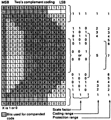
So long as the decoder is continuously fed with information on which of the five possible coding ranges is in use at the compressor from moment to moment, it can reconstitute a very close approximation to the original signal. This scale factor is conveyed by a 3-bit data signal as shown in Fig. 9.1. The various scale factors require different levels of protection against data corruption in transmission, as shown in the right-hand column of the diagram.
Data protection
Because of the risk of data corruption or distortion in the transmission path, protection must be provided in the form of a check or parity bit added to the end of each word. Here even parity is used to check on the word’s 6 most significant bits. At the encoder the 6 MSB are added together, modulo-two, to give a result of 1 or 0. The parity bit is given the same value so that the modulo-two addition of the 6 MSB and the parity bit should always be 0. At the decoder, parity checking detects simple errors and permits correction.
The parity bits are also used to signal scale factor information to the decoder. They are modified in accordance with a look-up table held in memory at both ends of the chain. The 3-bit scale factor word is extracted at the decoder by majority-decision logic, while retaining (except during circumstances of heavy data corruption) the parity-check facility. The scale factor information enables the decoder to recreate any bit in the left half of the block of Fig. 9.1 which was removed during the digital compression process. Any bits removed from the LSB side of the word (right-hand top and bottom in the diagram) cannot be restored, but their loss is masked by the fact that their samples are not crucial ones noise-wise.
Thus full 14-bit resolution is given to the small vulnerable signals corresponding to range 5, falling in four steps to 10-bit resolution in range 1, which corresponds to the largest audio signals. This economy in bit-rate has little or no subjective effect on the listener.
For scale factor signalling purposes the protected 11-bit words are grouped together in blocks of 32, each block lasting for 1 ms. A 3-bit code word is sent with each block to indicate scale factor as shown in Fig. 9.1. Since only one such word has to cover 32 consecutive data words there is some inaccuracy here: not all words receive optimum expansion. In practice the decoder gets reliable information on the magnitude of the largest signal in each block, at a rate sufficient to track the fastest perceptible changes in loudness, and this achieves a subjectively high S/N ratio.
Bit interleaving
In a data transmission system protection must be given against impulsive interference or dropout, which otherwise would make an irreparable ‘hole’ in the datastream. It is achieved by interleaving the bits at the coder and reassembling them in the correct order at the decoder. This spreads and fragments any errors and enables the simple parity-check system to cope with quite large short-term errors.
The data is written into memory at the sending end, then read out non-sequentially according to a ROM address-sequencer which has a complementary counterpart in the decoder. By this means bits which were initially adjacent are transmitted at least 15 bits apart. Any damage is now distributed among several words, each repairable by parity protection and/or error concealment by interpolation.
Control data
So far we have only examined the signal data, that which conveys the audio information. To control and synchronise the decoding and signal-routeing processes at the receiver extra data must be added.
Fig. 9.2 shows the make-up of a broadcast data-frame, which occupies 1 ms and contains 728 bits. The frames are sent continuously, with no gaps between them. First comes a frame alignment word (FAW) to initiate and synchronise the decoding sequence. It consists of 8 bits and always has the sequence 01001110. Following this is the application control word consisting of 5 bits, C0 to C4. C0 is the frame flag bit, which alternates between 0 and 1 at eight-frame intervals. It defines a 16-frame sequence, and is used to synchronise changes in the type of data being sent. Bits Cl, C2 and C3 indicate the nature of the data broadcast according to Table 9.1 – it operates indication lights and route-switches at the receiver. C3 remains unchanged for all these options, but provides spare capacity which may be used in future for other sound and data coding options. C4 is a reserve sound switching flag, set to 1 when the Nicam system carries the same sound programme as the conventional f.m. sound carrier, and to 0 otherwise. It is used to mute the audio amplifier/loudspeaker when data other than TV sound is being sent, and for switching between f.m. and Nicam sound systems as circumstances and users require.

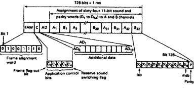
Following the application control bits come 11 AD (additional data) bits whose use and contents have yet to be defined. The rest of the frame is given over to the sound data whose conditioning we have already examined.
Audio data
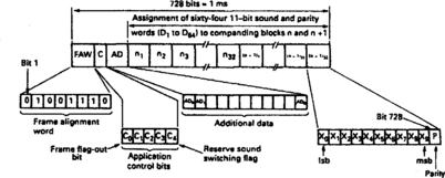
The sound data bits are arranged in 64 11-bit words as shown in Fig. 9.2. For a stereo programme the A samples (L channel) and B samples (R channel) are sent alternately: 32 of each. In a monaural transmission the frame is arranged with two 32-word blocks (n and n + 1) placed end-to-end in a single frame, as shown in Fig. 9.3. The sound signal is carried in odd-numbered frames, leaving gaps which can be used if required for a second monaural (e.g. bi-lingual) sound track or for the transmission of other forms of data: for downloading into a computer, for instance. For mono sound, Table 9.1 indicates that the control code would be 100 (switches receiver to mono mode); for two independent mono signals the code changes to 010, and M1 or M2 can be selected by the user.
Scrambling
The data will be used to modulate a carrier, and fixed patterns in the datastream set up fixed sideband patterns around the carrier. This is undesirable from the point of view of interference to co-channels and adjacent channels in the broadcast band, so the datastream must be scrambled to make it appear random and noise-like. The frame alignment words are not scrambled because they initiate the descrambling process at the decoder.
At each end of the chain is a PRSG (pseudo-random sequence generator) which generates a sequence of binary digits in a fixed and repeatable pattern. Each PRSG is reset on the last bit of the frame alignment word, and its output is added modulo-two to the data bits. The effect is of a completely random bitstream in the transmission channel.
Modulation
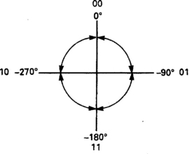
The data is now ready for transmission and must be modulated onto an r.f. carrier. The system used is four-phase modulation, which is economical of bandwidth. The carrier has four possible rest states – 0°, 90°, 180° and 270° – and is switched between them by the Nicam data. A serial to 2-bit parallel converter changes the serial data into a series of 2-bit pairs, which can only be 00, 01, 10 or 11. Each of these alters the carrier phase by a different amount, as shown in Fig. 9.4, from its previous rest state. Only a 00 bit pair will have no effect on carrier phase.
Carrier phase changes, then, take place at 2-bit intervals with a maximum shift of half a cycle of carrier frequency. To avoid sudden sharp changes of carrier phase the data is fed through a spectrum shaping filter on its way to the DQPSK modulator. This has the effect of ‘smoothing’ the transitions and quietening the sidebands. For system I transmissions (UK, Ireland etc.) the filter used gives a maximum sideband spread of 700 kHz. For system B/G transmissions as used in most of Western Europe a sharper filter is used to limit the spread to 500 kHz and thus avoid interference with the nearby f.m. sound carrier.
Nicam carrier
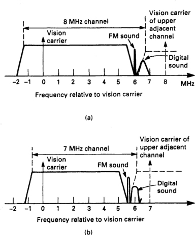
In system I the f.m. sound carrier is 6 MHz above the vision carrier at a relative level of −10 dB. The Nicam carrier is spaced 6.552 MHz (nine times bit rate) above vision carrier at a level of −20 dB, see Fig. 9.5(a). For system B/G transmitters the Nicam carrier is at +5.85 MHz as shown in Fig. 9.5(b).
The Nicam format is compatible with the MAC/packet system used for satellite transmissions so that chip sets developed for the one can be used for the other.
RECEPTION AND DECODING
The processes at the receiving end are the inverse of those carried out by the Nicam encoder, applied in reverse order to recreate the L and R baseband audio signals which were present at the studio microphones. The take-off point for the Nicam carrier is at the output of the tuner of the TV set or videorecorder, where it appears as an i.f., typically at 32.95 MHz. This frequency is beat against the vision i.f. to produce an intercarrier frequency at Nicam carrier rate: 6.552 MHz for system I, 5.85 MHz for system B/G.
DQPSK demodulation
Fig. 9.6 shows an internal block diagram for a commercial DQPSK demodulator IC as used in domestic receivers. The Nicam carrier enters at pin 4 at a level of about 60 mV r.m.s. It passes through an a.g.c control stage to maintain a reasonably constant input level to a pair of detectors, A and B. They are arranged as synchronous demodulators working in quadrature, rather like the U and V detectors of the PAL decoder described in Chapter 7. Emerging from these are in-phase (cosine) and quadrature (sine) components of the phase-modulated carrier signal. They leave the IC on pins 10 and 11 for passage through separate but identical shaping filters whose characteristic is the same as those used at the DQPSK modulator at the transmitter. They remove harmonics and optimise the noise performance of the decoder.
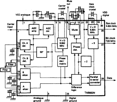
The filtered quadrature signal components re-enter the chip on pins 19 and 20 for application to a pair of adaptive data slicers, A and B, whose operating points are held symmetrically about the signal’s midpoint. The data outputs from the slicers are applied to a matrix and phase-locked-loop, PLL, to generate a synchronous c.w. feed for the detectors already described. The main path for the data signals is to a differential decoder, which uses a second PLL for sampling. It is here that 0 or 1 decisions are taken. The decoder output contains the bit pairs into which the data was grouped at the transmitter’s modulator. After passage through a 2-bit parallel to serial converter, the demodulated datastream emerges on IC pin 29 for application to the Nicam decoder proper.
The crystal oscillator in the second PLL in this IC runs at 5.824 MHz, eight times the bit rate of 728 kHz. Its output is divided by eight to provide: a bit clock drive for the following demultiplexer chip via pin 27; an internal drive for the P-S converter stage; and via a ÷2 stage a drive at 364 kHz for the differential decoder and the phase detector which steers the PLL. If the loop comes out of lock no coherent data can be detected and the mute output goes low on IC pin 18.
Demultiplex
The second main IC in this Nicam decoder is called a demultiplexer; it descrambles, de-interleaves and reformats the sound data to present an output suitable for application to a conventional D–A converter system, along with the necessary clock and ident outputs. A typical demultiplexer IC is shown in block diagram form in Fig. 9.7. It has provision for fall-back switching to f.m., language selection, and control by direct line or serial data bus.

Data enters the IC on pin 23 wherefrom it takes two routes, one for signal and one for control. The latter starts with the FAW detector, consisting of an 8-bit serial register and comparator. Once the 01001110 FAW sequence is detected the PRSG generator is reset and started. Its synchronised output is added to the datastream to descramble all the bits which follow the FAW. The control bits are now routed to their own decoders to provide audio route switching and status indications for the user. The data proper passes outside the chip (pins 7/15) for interception if required, then to a serial to parallel converter whose 64 outputs consist of all the bits in two blocks of data. They are loaded into 64 × 11-bit memories in order to carry out the de-interleaving process, which consists of reading out from memory in the required order, controlled by an address sequencer governed in turn by the ROM-based interleaving code. Two memory banks are used, one being written as the other is read to render alternate A and B samples for stereo use. A third memory is incorporated for use with M1 and M2 (two mono, bi-lingual) transmissions where both are present in alternate blocks as shown in Fig. 9.3.
The 11-bit protected words, now descrambled and de-interleaved (but not yet error-corrected) must now be expanded back to 14-bit form. The scale factor information held in the parity bits is extracted, assembled and interrogated to control the data-expand stage, from which emerge 14-bit data words ready for error-correction and repair. This is carried out in the error-check block with reference to the parity bits for simple correction; and to the protection range data (conveyed by the range code) for more sophisticated error-concealment using interpolation, a process of replacing suspect data with locally generated samples derived by ‘averaging’ adjacent known-good samples.
Data leaves the IC on pin 3. It consists of alternate bursts of A and B (stereo L/R) information, defined by an ident (flip-flop) signal at pin 33, and a clock drive at pin 4. These three feeds go to the D–A converter stage from which the baseband signals will be reconstituted.
The bit clock signal from the demodulator chip enters at pin 22 for use in the FAW detector. The main clock within the demux IC runs at 5.824 MHz and is also derived from the demodulator chip via pin 28: it is used throughout the Nicam decoding sections. A third clock signal, derived from the crystal at IC pins 11 and 12, provides a 16.384 MHz drive to the D–A converter.
Early designs of demultiplexer IC used external RAM for data interleaving, but all current types have on-board memories for this purpose, and work in broadly similar fashion to that described here.
D–A conversion
Conversion of the data back into analogue form is the final process in the Nicam decoder. The circuits and principles used are the same as those in audio CD players. In both cases the L and R audio information is contained in the same datastream, which alternates between the two.
Generally an integrating type of D–A converter is used. Its principle of operation is to charge a precision capacitor from a constant-current source for a period set by the data in each 14-bit word. A hold circuit is used to maintain the charge level between samples. Separate integrating capacitors are used for L and R channels, selected in turn by the L/R switching feed from the demultiplex chip. The outputs from the D–A converter now undergo filtering to remove sampling components and smooth the ‘stepped’ output waveform. In simple decoders the filters cut off sharply above 15 kHz; more sophisticated designs use oversampling with a smoother roll-off in the analogue filter, another technique widely used in CD players. This prevents distortion and coloration of audio signal components between 12 kHz and 15 kHz.
At the outset the L and R signals underwent pre-emphasis and now the complementary de-emphasis is applied to restore correct balance throughout the frequency spectrum and reduce noise. The L and R signals are now ready for audio amplification and application to loudspeakers in the case of a TV set, or processing for Hi-Fi recording in a VCR. All Nicam-fitted equipment has audio output sockets to facilitate connection to other units, most commonly a separate Hi-Fi system with good performance and high-class loudspeakers.
Fully integrated sound processor
Although the Nicam decoder system illustrated in Figs 9.6 and 9.7 is a good model for a functional description and understanding of the demodulation and decoding functions, it has been overtaken by various types of one-chip processors. That illustrated in Fig. 9.8 (MPS3410) provides a complete sound ‘package’, taking a sound i.f. input and producing stereo outputs for direct application to headphone and loudspeaker amplifiers. Demodulation and filtering is performed in-chip and is programmable; the stereo outputs can be controlled in terms of volume, balance, loudness, bass, treble and stereo ‘width’ enlargement, and can be made to produce pseudo stereo from a mono source, all governed from the control system via an I2C bus. F.m.-mono and f.m.-stereo (e.g. zweiton) transmissions are also catered for in this IC, and automatically selected in the absence of a Nicam signal.

There are two i.f. input pins (58 and 60), typically connected to terrestrial and satellite receiver sections respectively. Initially the input signais are A–D converted and a.g.c-controlled before demodulation and application to the DFP (Digital Field Processing) block which contains demodulator and Nicam decoder; this performs all the functions described earlier in this chapter, including on-board D–A conversion.
Once the Nicam or f.m. signals have been restored to baseband form, their characteristics of volume, tone, balance etc. are controlled by I2C data. An important feature of this chip is its ability to select and control auxiliary audio inputs entering the set via SCART and phono sockets and hence the IC via its pins 46–55. Selection and control is again governed by the I2C bus; the selected input signals are A–D converted within the chip so that they can be manipulated and processed in the same way as the broadcast signals produced within the demodulator/decoder section of the device. In TV-standby mode the chip automatically defaults to ‘SCART-through’ mode to permit copying.
SERVICING NICAM DECODERS
Because Nicam circuits are largely digital in operation, and because they dissipate little power, they are among the most reliable sections of TVs and videorecorders.
Alignment
Some early DQSPK demodulator ICs have external trimmers for adjustment. The type shown in Fig. 9.6 has one associated with pin 6 for setting the carrier clock. It should be adjusted for 6.55185 MHz ±50 Hz with an accurate frequency counter and no Nicam signal applied. Alternatively an oscilloscope can be used, synchronised externally from IC pin 22 and displaying the waveform at pin 20. With a Nicam signal present adjust for maximum eye-height in the pattern shown in Fig. 9.9.

The data clock frequency also has an external adjustment in this type of chip, in the form of a trimmer at pin 22. Adjust for zero volts ±30 mV on a digital voltmeter connected between pins 12 and 21 (Nicam signal present) or alternatively for 5.824 MHz ±20 Hz at pin 26 with no Nicam signal present.
In the demux chip illustrated in Fig. 9.7 provision is made for setting the DACLK frequency: adjust the trimmer at pin 12 for a frequency of 16.384 MHz at pin 11. Other types of demux IC have no need for manual adjustment.
Some decoder designs have an adjustable bandpass filter in the 6.552 MHz feed to the DQSPK demodulator IC. It is set for best eye-pattern at the spectrum-shaping filter, e.g. pin 20 of the IC in Fig. 9.6. Setmakers usually give specific alignment instructions for this filter.
Fault tracing
Seldom do Nicam decoder faults give rise to ‘borderline’ symptoms. As with most digital processors the device tends to either work perfectly or not at all, due to the various mute systems which come into operation when a PLL unlocks or in the presence of heavy data corruption. In that event the receiver will generally fall back to conventional f.m. (mono) operation, signalled by front-panel or on-screen indications.
If there is no Nicam reception first ensure that the TV transmission is in fact Nicam-encoded, and that any system switch or installation/user software is correctly set. After checking that the ICs are getting correct Vcc supplies, examine the level of the signal at the mute pin of the first IC: in Fig. 9.6 this is no. 18. If it is low (mute on) check that the Nicam carrier is reaching the chip input, and then that the PLLs are locked, here indicated by correct clock rates as described above. If the mute line is high (mute off) the fault lies further downstream in the decoder, probably around the demux chip.
In these circumstances the first tests should be at the data and clock signal inputs to the demux chip, and the outputs from the IC to the D–A converter: clock, data and ident. If the latter are missing or incorrect, check that the PLL within the IC is working and locked up before suspecting the peripheral components, and then the chip itself, in that order. Most Nicam ICs have test/switching pins which can be identified from the IC manufacturer’s (or setmaker’s) data and used in fault diagnosis.
If the Nicam sound is distorted the cause is unlikely to lie in the digital sections of the decoder: as a general rule they will automatically mute before operating conditions deteriorate to the point where sound reproduction is impaired. For distortion, then, the starting point for tests should be the D–A converter IC if both channels are affected and supply voltage levels are correct. Any fault which is confined to one of the L/R sound channels will not arise from the digital section of the decoder because both are handled together there. Using an oscilloscope, check the output signals from the low-pass filters immediately following the D–A converter, and then continue downstream in the faulty channel until the trouble is located. The fact that two identical channels, one working correctly, are present is a great help in diagnosis because comparison tests can easily be made.