
SATELLITE TELEVISION
TV FROM SPACE
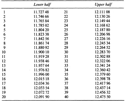
The concept of modern communications satellites was first put forward by Arthur C. Clarke in 1945, and first implemented in 1965 by Early Bird, built and launched in the USA. It is based on the use of a geosynchronous orbit in the plane of the equator, wherein the satellite orbits at an altitude of 36 000 km at a speed of 11 000 km/h. Under these circumstances it appears stationary to an observer on earth, and can act as a ‘mirror in the sky’ to radio waves. The sky-path 36 000 km above the equator is called the Clarke belt and individual spots on it are known as orbital slots. These slots are defined and allocated by international agreement. The governing body for satellite slot allocation is the World Administrative Radio Conference (WARC), whose allocations are given in Table 4.1 and channel frequencies in Table 4.2.
Table 4.1
DBS allocations – positions, channels and polarisation
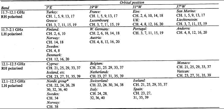
*Wide beam channels: Denmark, Finland, Norway, Sweden.
The satellites are powered, for both transmission and internal ‘housekeeping’ services, by solar energy, intercepted by banks of solar cells on dragonfly-type wings which are kept facing the sun. Transmissions to and from the satellite are in the Ku band, 10.95–14.5 GHz, concentrated into very narrow (and thus intense) beams by parabolic reflectors – dishes – at each end. Medium-power satellites like Astra 1A and 1B typically have transponder powers of 45 W, receivable with a dish of about 60 cm diameter in the primary service area. The DBS transmissions have higher power (say 100 W per transponder) and call for an antenna of about 35 cm diameter in the primary service area, centred on the receiving footprint. Typical footprint diagrams are given in Fig. 4.1.

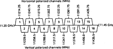
A medium-power satellite typically has 16 transponders, whose footprints are not necessarily the same: by special antenna arrangements spot beams can be designed to cover different areas on the earth. The higher-power DBS satellites have five or ten transponders. All analogue TV transmissions from satellites are frequency-modulated to take advantage of the f.m. system’s greater immunity from noise interference. The carrier wave from a satellite can be polarised in either linear or circular fashion. The polarisation characteristic is used to discriminate between co-channels or adjacent channels: interfering carriers in the wrong polar field are rejected by up to 22 dB, enabling the carriers from individual transponders on a single satellite to overlap without mutual interference. Fig. 4.2 shows the ‘staggered’ arrangement of carriers on a typical set of transponders.
Most satellite channels are 27 MHz wide; the Eutelsat II transponders are an exception at 36 MHz. The f.m. transmissions carry an energy-dispersal waveform which prevents the carrier frequency dwelling at one spot during such repetitive picture features as black-level, syncs and peak white: this avoidance of spot-frequencies lessens the risk of interference to other services.
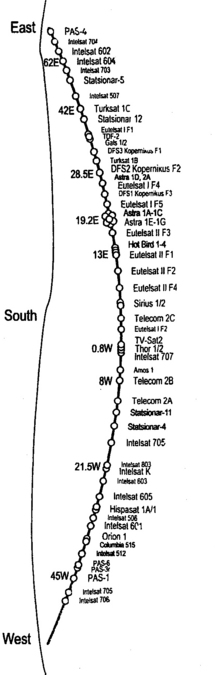
The orbital slots in the Clarke belt of interest to European viewers are shown in Fig. 4.3. At present the most popular of these for direct-to-home services is the Astra group at 19.2°E. A single receiving antenna/dish can be fixed to a polar mount and made to scan the entire Clarke belt by manual or automatic (governed by the receiver’s microprocessor control system) means, but polar installations are not nearly so popular as simple, inexpensive fixed-dish outfits. World allocations for DBS satellite positions are the subject of Fig. 4.4.

Many satellite picture transmissions are scrambled or encrypted to prevent unauthorised viewing, generally by those who have paid no subscription, or by those who live in areas for which copyright release has not been obtained for the broadcast material. Many different scrambling systems are in use, some of which have to be frequently updated to keep ahead of the designers of ‘pirate’ decoders. Authorised decoders typically use a ‘smart-card’ containing data which, with the descrambling information carried in the broadcast itself, provides clear reception.
The MAC system was the only analogue one which was designed specifically for use with satellites, and gives far superior results to other systems. Non-MAC satellite transmissions, scrambled or not, use the same basic TV system as the terrestrial transmissions in the country for which they are intended, which generally means PAL/625 for Western Europe, Secam/625 for Eastern Europe and parts of the Middle East, and NTSC/525 for North America and Japan. The use of established colour-encoding systems is far from ideal for satellite use with frequency modulation, but confers compatibility with existing TV equipment in the home, a compromise which most viewers seem very ready to accept.
Again excepting the MAC transmissions, sound is broadcast on f.m. carriers typically spaced 6.5 MHz above the vision carrier. Stereo sound, using an analogue modulation format and a noise-reduction artifice such as the Wegener-Panda system, is used, and certain programmes offer bi-lingual sound channels. For these ‘audio extras’, narrowband sound carriers are used: in Astra transmissions they sit 7.02, 7.20, 7.38 and 7.56 MHz above the demodulated vision carrier. The audio signals on these carriers are not necessarily related to the video images on whose backs they ride; specialised and general ‘radio’ stations occupy them in some transponders. Digital radio transmissions are also present on some of the transponders: more details later in this chapter.
This plethora of transmissions, sound and vision, from the sky is uplinked from control/relay stations on Earth, using frequencies in the region of 14 GHz to convey not only programme signals, but also control, monitoring and telemetry commands and feedback. Thus is the satellite kept in position and on target.
In this chapter we shall examine analogue satellite systems. Digital ones will be covered in Chapter 12.
SATELLITE RECEIVING ANTENNAS
Even though the broadcast signal from a satellite is concentrated into a narrow and relatively powerful beam, it cannot be usefully intercepted by a dipole in the same way as longer-wavelength signals. It is necessary, then, to use a large-area collector of SHF signals in the form of a dish or plate to increase the capture area. Most common is the dish aerial in which a parabolic reflector concentrates the signal beam onto a tiny metal patch or probe inside the low-noise-block (LNB) at the focal point of the dish, Fig. 4.5(a). Manufacture and handling of the dish is crucial because its surface must be true enough to ensure in-phase arrival of all the SHF carrier cycles at the pick-up point.
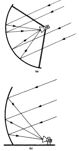
Practical satellite dishes do not have to be completely parabolic in shape: it is sufficient for them to take the form of a section of a parabola so long as the LNB is at the effective focal point. The offset dish, shown in Fig. 4.5(b), is used for domestic reception; it has the two advantages of keeping the LNB’s ‘shadow’ out of the path of incoming signals, and presenting a more nearly vertical face from which water and snow easily fall away There are other dish configurations, one of which has the LNB at the rear of the dish, looking at a subreflector at the main focal point.
Dish gain and efficiency
A typical efficiency figure for a receiving dish is 60%. The gain increases with dish size, of course, and the larger the dish the better the received signal. Dish size is a compromise between many factors; for aesthetic, economic and physical reasons home-mounted dish antennas need to be as small and unobtrusive as possible. A large dish has the advantages of providing a greater margin to accommodate losses due to rain, snow and gradual deterioration of efficiency in the system; and a narrower beamwidth, giving greater immunity from interference by other satellites in the burgeoning Clarke belt. It is, however, marginally more difficult to install, more obtrusive, and imposes more strain on its mountings in high winds.
The continuing improvement in LNB noise figures has made it possible to use smaller dishes to achieve the required carrier/noise (C/N) ratio, and the greater the EIRP (Effective Isotropic Radiated Power) of the satellite on which it is targeted, the smaller the dish needs to be. In general, dishes of less than 40 cm effective diameter run the risk of picking up interference from other satellites. Thus it is unlikely with current technology that the norm will be less than 40 cm.
Rain or snow in the air tends to absorb microwave radiation, and short-term signal losses of 3–10 dB can be experienced in heavy weather. In an average installation very heavy rain will reduce the C/N ratio below the system’s noise threshold, the effect of which is sparklies (black and white horizontal dashes) superimposed on the picture. Seldom in Europe or North America does it rain hard enough or long enough for this to be a significant problem, however.
For fixed-dish installations, manufacturers generally provide a complete kit consisting of antenna, LNB, mountings and receiver, all matched to a specific satellite whose EIRP is well established and defined. Used together, the components of such a kit work well so long as the installation is correctly done and the maker’s recommendations of dish-size/LNB specification for different geographical areas is followed. If, however, it is required to mix head-end components of different makes; to match two LNBs to a single dish; to receive low-power or footprint-margin transmissions; or to install a polar-mounted dish other than a custom-made outfit, it is necessary to take into account many factors when specifying the dish, LNB and receiver. This is called a linked budget calculation, covered (with computer program details) in Newnes Guide to Satellite TV by D. J. Stephenson.
Dual-feed systems
There are several forms of dual-feed system for satellite reception from a single dish. Where two or more receivers share a dish a dual-LNB can be used, enabling each viewer to select the programmes required in respect of their polarisation. For MATV installations this type of LNB is also used, here to provide separate feeds of horizontally and vertically polarised signals for amplification and splitting in a distribution amplifier.
Where reception from more than one satellite is required there are several choices. The simplest and most reliable is the dual-LNB arrangement shown in Fig. 4.6. Here a special bracket supports two LNBs which face the dish at different angles, typically about 6° apart for reception from the Astra (19.2°E) and Eutelsat (13°E) birds. With the dish aligned on the mid-point between them, each satellite’s signal beam is seen only by its ‘own’ LNB due to their different reflection angles and thus each downlead conveys the signals from its own satellite, generally to a receiver with two LNB input sockets and auto-selection of the feed required. An alternative to this is the motorised LNB, which is driven across the face of the dish to ‘see’ any point in a narrow arc of the Clarke belt, narrow because the efficiency of the dish as a reflector drops off sharply a few degrees off centre.

Further choices for multi-satellite reception are a wide-arc dish with several LNBs mounted on a curved boom in front of it, an extension of the set-up illustrated in Fig. 4.6; and a motorised dish on a polar mount, in which the whole assembly, single LNB included, is driven from horizon to horizon (H-H) if required, under the control of the viewer and a computerised auto-seek system. More details of polar mounts and motor-driven dishes are given in Newnes Guide to Satellite TV.
Beamwidth
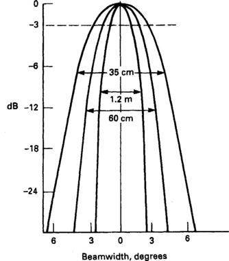
The beamwidth of a dish is inversely proportional to its size, whether it is transmitting or receiving. Footprint shapes and sizes are wholly determined by the design of the satellite-mounted dish, which is ‘fine-tuned’ to give the coverage required by the broadcaster in terms of countries and areas – see Fig. 4.1. Regardless of which end of the chain a dish may be, the beamwidths are represented by cones of 2° angle for 1 m types, 3° angle for 50 cm, and 4.5° angle for 35 cm. The angles are based on half-power (-3 dB) points as shown in Fig. 4.7. there are also side-lobes (not shown in the diagram) on each side of the main aiming path, but their response is typically 20 dB down on the main beam, so they are less likely to contribute interference than to increase the noise component of the received signal. The nature of the spurious lobes depends greatly on the type and design of the dish and LNB unit.
C/N ratio
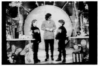
The arbiter of reception quality is the carrier-to-noise ratio. A C/N ratio of 10 dB gives satisfactory results, but leaves little safety margin. We may regard 11 dB as a norm for currently available equipment, and 13.5 dB or more is excellent. As the C/N ratio decreases, there is little effect on the picture until the threshold level of the receiver’s f.m. vision demodulator is reached, when sparklies begin to intrude on the picture. With terrestrial-type (e.g. PAL, NTSC) colour-encoding systems the interference is most obtrusive on highly coloured areas of the picture. As LNB noise figures and carrier detector designs improve, the required C/N ratio becomes less. An offscreen picture of sparklie interference is shown in Fig. 4.8.
Environment-friendly dishes
The fact that (in the northern hemisphere) satellite receiving antennas have to point south means that the physical positioning of a home dish is seldom a matter of free choice, though a great deal can be done to hide or disguise the antenna with careful thought and choice of type. Where the dish has to be visible, there are three ways in which its obtrusiveness can be reduced: by painting, by making the dish transparent, and by using an open-mesh construction.
Any conventional dish type can be painted – ideally with spray application – to make it merge into the background against which it is seen. Some dishes come in a choice of colours, but it is generally necessary to spray the dish after installation, giving a thin and even coat of matt or eggshell-finish paint.
Glass dishes use metallised armoured glass with 99% reflectivity to microwave radiation. They are more expensive than the simplest (pressed sheet metal) types, but are more rigid, reflect less heat onto the LNB assembly, and of course are less obtrusive.
The reduction of visual impact represented by a mesh dish (they are usually black) is somewhat questionable, but they are established in production. Their weight and wind-resistance is less than that of conventional types for a given size, and the perforations have little or no effect on their efficiency. They tend to be more flexible, however, which can be detrimental in high winds.
Flat-plate antennas
An alternative to the parabolic dish is a flat-plate antenna, sometimes called a squarial. A flat board is fitted with an array of many hundreds of small ‘dipoles’ in the form of patches, lines or slots. The tiny signal currents induced into them by the r.f. radiation are combined in phase and conveyed by a waveguide of some type to a common point where they enter an LNB. For the same surface area a flat-plate antenna has less gain than a parabolic dish arrangement, and above a certain size (about 50 cm square) the efficiency of a plate array falls rapidly. As technology improves, however, flat antennas may become more popular, especially as they have the potential to be cheaper, easier to install and less obtrusive than dishes. It may also be possible to incorporate ‘electronic aiming’ of flat plates by internal phase-switching, an attractive possibility for multi-satellite reception. Domestic satellite antennas are the subject of intense research and development.
RECEIVER INSTALLATION
The first step in the installation of a satellite antenna is a site survey, consisting basically of a careful assessment of where and how the antenna should be mounted. It must have a clear view of the southern sky in the direction of the satellite of interest. It needs a strong mounting surface, ideally a brick or masonry wall, or for ‘patio mounts’ a concrete base. It should be as near as possible to the cable’s entry point to the viewing room to save the expense and signal attenuation of long cables. It should ideally be out of sight of the street and as unobtrusive as possible anyway. Planning regulations demand that special permission be sought for mounting above the line of the roof apex.
Safety
Strict regulations cover the safety (of the installer, the customer and the general public) of antenna installations. In general, safety has two aspects: that of the installer, customer and bystander while the work is carried out; and that of the dish and fittings themselves throughout their working life.
During installation the main precautions concern ladders, which should be firmly based, perfectly upright and at a slope near 4:1; electrical tools, which should be regularly safety tested; and eye protection, which should be worn throughout hammering and drilling operations.
Regarding the subsequent safety of the installation, the key points are that the dish-mounts are strong, reliable and fixed to a strong and stable base, and that the equipment presents no shock or fire hazard due to bad handling or practice.
Dish mounting
Once the mounting point for the antenna has been decided upon, the first essential is to get as strong and reliable a fix as possible. The most common – and best – fixing is into a brick or concrete wall, avoiding the chimney wherever possible. Whatever type of anchor is used on a brick wall it is important to fix it into brick rather than mortar, and to keep the holes near the centre of the brick where possible. If the brick wall has been rendered, ‘test borings’ establish the positions of mortar courses.
Mounting holes are easiest drilled with a powerful electric hammer drill and a tough masonry bit. Hole sizes and anchor types are usually recommended by the dish manufacturer, based on the size and weight of the antenna assembly and particularly its likely wind loading, which can increase the effective weight/pull by a factor of 10.
For small light antennas, high-quality plastic wall plugs are perfectly adequate so long as they are matched in size to the fixing screws, which must themselves be of the correct diameter for the fixing holes, and of non-corroding type – plain steel screws rapidly rust out of doors. Larger and heavier antennas require expansion anchors or special purpose-designed variants. They provide the strongest and most rigid fixings, but should be avoided in low-density materials like breeze-blocks, which have low compressive strength. For situations where wall mounting is not possible, pole fixing is an alternative for which special kits are available; the pole must be stout and very rigidly mounted and braced.
Alignment
Once the dish is fixed, alignment can begin. The relatively small antennas used for domestic reception are not difficult to align, given the three essential aids: a compass, an inclinometer (basically an enlarged protractor) and a signal-strength meter, which is incorporated in some receiver designs.
Tighten the securing screws a little so that the dish can be moved, but is not floppy, and then set the azimuth (panning action) according to the published orbital position of the satellite and with reference to the compass. Next, using the inclinometer or the printed/stamped graduations on the mount, set the elevation (tilting action) to be required point. Bear in mind that the elevation setting for an offset dish must take into account the offset angle.
When the aiming is approximately correct some vestige of picture and sound will be present on a pre-tuned receiver or on a simple field-strength meter. The dish can now be trimmed in respect of both azimuth and elevation to peak the signal strength, ensuring that the installer is not casting a ‘shadow’ on the front of the dish. When the maximum possible signal strength has been achieved the dish-mounting bolts can be fully tightened, and then greased as a precaution against corrosion. Fig. 4.9 and 4.10 show elevation and azimuth settings throughout the UK for the Astra and Eutelsat/Hot Bird satellite groups respectively.
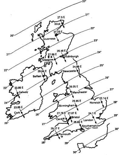
Fig. 4.9 Dish-setting parameters for Astra group, 19.2°E. The continuous lines indicate elevation angle

Some dish assemblies require adjustment of the LNB position to optimise focus and polarisation settings. Focus is simply achieved by moving the LNB to or from the dish to achieve best signal strength. Polarisation is set by rotating the entire LNB to the point specified by the manufacturers, or (more accurately) for minimum field strength on the ‘wrong’ polarisation setting: this gives a sharper null, more accurate alignment and greater immunity from interference/crosstalk than setting for maximum signal with correct polarisation for the transponder to which the receiver or field-strength meter is tuned.
Alignment of a polar-mount antenna is much more demanding. The basic requirements are a very accurate setting of the dish to true south at the apex, the centre of its travel, and a true-vertical setting of the mount’s position. Polar-mount outfits come with very detailed and specific setting-up instructions, which should be closely followed.
Where the receiver does not incorporate an inbuilt field-strength meter, or where it is physically impractical to use it, a hand-held type can be taken to the dish to aid alignment. The simplest and cheapest type (dish-peaker) gives no absolute indication of signal strength and has a broad frequency response: its indication is the sum total of all the signals picked up by the dish. It is perfectly adequate for the pointing adjustment, however. More expensive meters are tunable to individual transponders and may give a true strength reading in millivolts or dBu. The most comprehensive (and expensive) meters give a spectrum display of the satellite band on a CRT or LCD indicator to show relative and absolute strength of all the carriers received. Either of the latter types can be used for polarisation setting as well as dish-pointing. Fig. 4.11 shows a simple and inexpensive dish-peaking meter.

Cables and routeing
The link from the dish to the receiver carries frequencies in the range of 950 MHz to 2.15 GHz, too high for use with ordinary UHF TV aerial cables. A special low-loss cable type such as CT100 or H109F must be used: its attenuation at 1.3 GHz is about 23 dB per 100 m, and a maximum run of about 40 m is possible without the use of in-line amplifiers.
In most systems the coax cable itself carries the operating voltage (typically 15 V) to the LNB, and in some cases it carries a d.c. polarisation switching signal as well. Other designs call for a separate pair of conductors for polarity switching. Special cables containing low-loss coax plus separate conductors are available, but it is generally cheaper and more convenient to run a separate (mains-type) twin-core lead alongside the signal cable for this purpose.
The downlead should be provided with a drip loop at each end, and very thoroughly sealed at the points where it enters the LNB and the dwelling; with self-amalgamating tape or a rubber boot at the top, and a mastic sealer at the bottom. Tack up the cable at 50 cm intervals on vertical runs and 20 cm on horizontal runs, following the most unobtrusive route, e.g. under the eaves. Avoid tight bends, which stress the cable physically and cause excessive signal attenuation; a bend radius of 10 times the cable diameter is the minimum acceptable. As a precaution against lightning and static damage it is good practice to ground (earth) the dish metalwork and the braid of the downlead.
Indoor installation
Ensure that the receiver is unplugged (not just switched off) until all wiring and connections are complete. The satellite tuner (some of them run very hot) should be sited on a hard surface with plenty of room for air circulation around it. Most receivers and IRDs (Integrated Receiver/Decoders) come ready tuned, though some require the presetting of polarisation by memorising the setting for each preset channel for each mode, vertical and horizontal. Tuning and station memorisation are described in the user’s handbook – many different systems are in use.
Hook-up
The audio and video outputs are available from the satellite receiver in two forms: baseband, from a SCART socket; and r.f. from a UHF modulator tuned to channel 38 or 39, but adjustable over a range of about 10 channels for older receivers, fully programmable in software for newer types. It is best to use the baseband outputs whenever possible for the better picture and sound quality they offer, their immunity from r.f. interference, and their ability to handle stereo sound signals. Where the TV set or VCR in use does not have SCART sockets, or where they are already fully occupied, the r.f. connection can be used, though careful adjustment of the output channel trimmers of both sat-box and VCR will probably be necessary to avoid mutual interference and the resultant patterning effects.
Even when a baseband connection is present it is still necessary to maintain the r.f. link through the VCR to the TV so that all viewing and recording options are maintained. A typical hook-up is shown in Fig. 4.12. Where the satellite tuner and the VCR are both equipped for stereo sound, their full potential can only be realised with a baseband link: some VCRs and TVs are fitted with two SCART sockets, greatly simplifying hook-up in circumstances like these. SCART pin layout and functions are given in Fig. 24.2.

MAC satellite receivers have RGB outputs as well as those mentioned above, and unless they are connected to the TV set via a SCART lead, wired for RGB, much of the advantage of the MAC TV system is thrown away. VCRs have no means of dealing with RGB signals, but high-band types, e.g. S-VHS format, benefit in terms of picture and sound quality from SCART connections. To help with the sometimes difficult tasks of interconnection and interfacing, various switchboxes are available, some with simple mechanical switches and others with sophisticated auto-switching and routeing based on the ‘status’ flags carried on pins 8 and 16 of the SCART connector system.
The high-quality audio transmissions from satellite services, Hi-Fi VCRs and the Nicam broadcasts described in Chapter 9 have led to a tendency to interconnect audio and video equipment; most video gear is fitted with phono sockets from which leads can be taken to the AUX input of a separate audio amplifier as shown on the right of Fig. 4.12.
HEAD-END UNITS
The head-end unit is mounted at the focal point of the dish, and consists of two components: a feedhorn and an LNB. Both are weatherproofed for their outdoor environment.
Principle
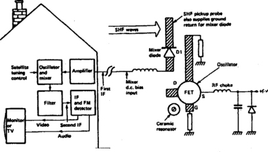
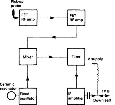
Reception at SHF is a heterodyne process, but involves two i.f. frequencies in a double superhet configuration. The first ‘local oscillator’ is installed at the dish antenna assembly in order to convert to a lower (and easier to handle) frequency as early in the signal chain as possible. The oscillator in the LNB is not adjustable: it runs at a constant and very stable frequency of about 10 GHz. Each incoming carrier beats against the oscillator to produce difference frequencies which represent the first i.f. so that, assuming an oscillator frequency of 10 GHz, an incident 11.650 GHz signal gives rise to a ‘difference’ i.f. of 1.650 GHz, an incident 11.674 GHz signal, an i.f. of 1.674 GHz, an 11.175 GHz signal, an i.f. of 1.175 GHz and so on. Thus the satellite transponders’ signals are ‘block converted’ to a lower band and appear in reverse order on the new, lower-frequency carriers which pass down the cable to the indoor unit. There they are tuned by a second superhet unit with variable local oscillator and fixed i.f. as already described in Chapter 3. The basic principle is shown in Fig. 4.13, though in practice there is a multistage r.f. amplifier between the pick-up probe and the mixer diode.
SHF front end
The signal radiation reflected from the dish is collected by a waveguide at its focal point. The open end of the waveguide is fluted to provide an approximate match between its characteristic impedance and that of ‘free space’; the front end of the horn thus formed is protected against water and other ingress by a sealed cap, transparent to SHF radiation. The shape of the waveguide horn is a matter of careful design since it determines not only the efficiency with which signals are collected, but also the shape and amplitude of the side-lobes in the directivity diagram (Fig. 4.7), and the bandwidth and noise performance of the ensemble. In commercial kits the dish, feedhorn and LNB are all matched, but care must be taken when assembling an outdoor unit from unrelated components.
The feedhorn/waveguide is bolted to the front of the LNB, which contains the pick-up device in which the SHF magnetic energy is converted to an electrical signal current. It is at this point that provision must be made for selecting the required polarisation of radiation, and rejecting signals arriving in the wrong polarisation. The two most common methods of selection involve no moving parts. One design has (printed on a glass fibre board) a micropatch on which the SHF signal is intercepted, with two adjacent printed ‘probes’ set at 90°. Each has its own r.f. amplifier which also acts as an electronic switch to select the required vertical or horizontal mode.
The amplifier in use, and thus the polarisation selected, is determined by the LNB operating voltage sent up the cable by the receiver: 13 V selects vertically polarised transmissions, 17 V selects horizontally polarised ones, while the 12 V or so required to power the LNB is cut off the bottom as it were.
An alternative system, not used for new designs of domestic receivers, uses a needle-probe mounted vertically in the LNB’s front aperture, capable only of intercepting vertically polarised signals. In the feedhorn is an electromagnetic polariser consisting of a coil wound on a ferrite core through which the incoming r.f. wave passes. Depending on the current flowing in the coil the wave’s polarisation is ‘twisted’ and at an optimum current exact alignment of the wave with the probe is achieved. Typically needing a d.c. current range of 70 mA to achieve 0–90° polarisation twist, these devices have low insertion loss but are frequency-dependent in their operation. A compromise setting can be made for a single narrow range of transponder frequencies, but where the system embraces a wide range of incoming signals – especially in a polar-mount system, where many satellites are addressed – provision must be made to optimise polariser current for each transponder.
DBS transmissions use circular polarisation, but all the transponders on each satellite have the same (either RH or LH) characteristic, so that LNBs designed for single-satellite use have fixed polarisation, and their design is simplified thereby.
LNB arrangement
Fig. 4.14 shows a functional diagram of a typical low-noise block. The pick-up probe is directly connected to an FET (Field Effect Transistor) made of gallium arsenide, GaAs, with tiny printed strip-lines 2–3 mm long as resonant circuits. One or two further stages of SHF amplification are provided to bring the signal level up to a point where it can be applied to a Schottky mixer diode, whose non-linearity ensures a strong beat signal, selected by filters and further amplified on its way to the output socket at the rear of the LNB module.
The local oscillator is also based on a GaAs FET: its output must be pure and noise-free and its frequency very stable with time and temperature. The tuned circuit is formed by a ceramic-based dielectric resonator mounted on the PCB between the drain and gate leadouts of the transistor, and not necessarily having any electrical connections to the circuit at all. The resonator may well have a screw-disc with which its frequency is preset at the factory.
The most important aspect of an LNB is its noise figure, normally quoted in dB, and indicating the relative amount of noise added to the signal in its passage through the device. Commercial LNBs for home use typically have a noise figure of around 0.8 dB, and current designs using HEMT (high electron mobility transistor) devices can achieve noise figures better than 0.5 dB. The overall gain of an LNB is about 60 dB, sufficient to launch the 1st i.f. signal into the downlead at a high enough level to overcome the losses in the cable.
The power requirement for an LNB is generally 13–17 V at about 200 mA, and is fed via the downlead, with signal and power separated at either end by L/C components.
Band- and satellite-switching systems
The 13V/17V polarisation switching arrangement is supplemented in modern installations by additional control signals coming up the cable from the receiver. ‘Universal’ LNBs are capable of receiving a signal spectrum of 10.7–12.75 GHz, switching between low-band (10.7–11.7 GHz) and high-band (11.7–12.75 GHz) operation by means of a dual-frequency local oscillator. It is switched between 9.75 GHz and 10.60 GHz by a 22 kHz tone, off for low band, on for high band; the tone level is about 600 mV peak-to-peak, superimposed on the supply voltage. In practice it is more commonly used to select LNBs than to change receiving bands, using commercially available tone-triggered changeover switches.
To address the problem of band- and LNB-selection Eutelsat designed a control system called DiSEqC, based on modulating the 22 kHz tone with digital data: software commands permit the choice of several LNBs as source feeds. The simpler variant can switch up to four LNBs and select their oscillator frequency and polarisation by means of data bytes in the control signal, while a later variant (Version 2.0) is bi-directional to permit feedback from the head-end to the receiver’s control system for status checking and (e.g.) control of a motorised dish.
SATELLITE RECEIVERS
There are two basic functions within an analogue satellite receiver: to select the required channel and to demodulate it to produce video and audio signals. There are many secondary functions – powering the LNB, selecting polarisation, status indication, provision for descrambling, selection of sound carrier, remodulation to UHF and others – but most of them have counterparts in other home video equipment.
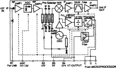
The first i.f. frequency, a block-converted group of channels containing the entire spectrum received by the dish ensemble and placed anywhere from 950 MHz to 2.15 GHz, enters the receiver and is amplified (Fig. 4.15) and a.g.c.-controlled. Image-rejection filtering is also carried out here. R.f. tuning is by lecher lines and varicap diodes, as in the conventional tuners examined in Chapter 3. The selected signal is applied to a mixer along with a second input from an oscillator whose frequency is varicap-controlled by a PLL tuning system of the type we have already met. The 2nd i.f., generally at about 480 MHz, is selected and extracted by a SAW filter with a bandwidth of 27 MHz. The filtered signal is amplified to overcome the SAW filter losses. After further amplification and close a.g.c. control the signal is brought to a level suitable for application to the vision i.f. demodulator. Before we leave this ‘tuner-heart’ section, note the prescaler and programmable divider within the dotted box. These are the essence of the tuning circuit: programme tuning data from the station memory enters the module at pins C, D, L (Clock, Data, Load/enable).
FM vision demodulator
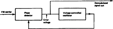
There are several ways to demodulate f.m. signals. The quadrature detector has already been described in Chapter 3, and other forms of modern f.m. demodulators will be examined in videorecorder applications in Chapter 14. An IC-based technology for recovering f.m. signals is the phase-locked-loop (PLL) system, and this is commonly used in f.m. vision demodulators.
A simplified block diagram of a PLL demodulator appears in Fig. 4.16. The incoming carrier is applied as one input of a phase detector whose error output governs the frequency of a VCO (Voltage-Controlled Oscillator). The second input of the phase detector is the VCO output, and since the phase detector’s error voltage steers the VCO until its two inputs coincide in frequency and phase, the oscillator (provided a short enough time-constant is present in the error-voltage filter) exactly follows the frequency of the carrier signal, including its deviation due to the modulating (vision) signal. Thus the error – or correction – signal, in pulling the VCO continually in line with the f.m. carrier, reflects (in its amplitude and polarity respectively) the amount and direction of all excursions of the carrier from its nominal centre frequency. In doing so it forms a perfect facsimile of the original modulating signal, which is what we want from a demodulator: in this case a video waveform similar in form to that of Fig. 2.5. PLL demodulators are also used in f.m. radio sets for broadcast and commumications reception, and in broadcast stereo decoders.
Integrated receiver/decoder
Fig. 4.17 shows a block diagram of an IRD (Integrated Receiver/Decoder) for reception of Astra transmissions. The tuner heart combines the functions of tuner, i.f. and vision demodulator, so that baseband video and sound signals are passed to the video input block, wherein is a de-emphasis circuit together with a clamp (to remove the energy-dispersal waveform), a sound-rejection trap, and output buffers. The main output goes from here to the video switch block which selects a direct signal or a decrypted one as necessary, passing it out to the SCART socket and the UHF remodulator. In the absence of a satellite carrier signal a tuning/identification pattern is automatically switched in, primarily to assist UHF tuning of the associated TV set.
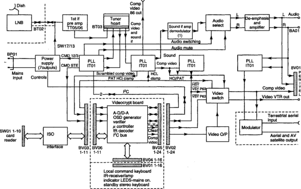
A second feed from the video input block passes to the sound demodulator section. It consists of a pair of f.m. demodulators, one each for left and right sound channels, working on carriers 180 kHz apart. These carriers (at 10.52 and 10.7 MHz for R and L respectively) are the products of a superhet process in which a local oscillator beats against the incoming audio f.m. carriers at (e.g.) 7.02/7.20 MHz. By controlling the frequency of the local sound-detector oscillator different stereo carrier pairs can be brought into line with the audio demodulators to select the required sound channel per transponder. It is done in preset software and selected by the control microprocessor IT01. Demodulated sound, after de-emphasis, is passed out of the box through the SCART interface, while the L and R signals are mixed for application to the mono-only UHF remodulator.
There are two further outputs from the ‘video input’ block. The composite video/baseband out can be used to feed a MAC decoder or a special decoder for extra subscription programmes etc. A feed is also taken to the Videocrypt board, on which the scrambled (subscription) transmissions are restored to normal video signals – so long as the fee has been paid! The sync separator stage, IL01, is a simple processor from which line, field and coincidence pulses are derived for use in the descrambler, which is digital in operation, and whose precise method of operation is a part of a confidentiality agreement between broadcaster and receiver manufacturer. A ‘smart-card’, purchased by the subscriber, is fed into the card reader, and so long as the data in the card is compatible with the transmission at the time, descrambling takes place. In this particular design the commands from the local and remote-control keyboards (the latter via an infra-red link) are also processed on the Videocrypt board – in the microcomputer control system, which governs all the functions of the receiver via the I2C bus examined in Chapter 22.
The power supply section of a satellite receiver is similar to that of a TV or VCR, and will be dealt with in detail in Chapter 11. For cool running and efficiency, switch-mode types are currently used. The PSU in Fig. 4.17 is of the switch-mode type and has seven output lines, not all of which are switched off by the control microprocessor during standby mode, when the r.f.-through amplifier, the remote control receiver/decoder and the display system must be kept in operation. The LNB is powered at all times to prevent thermal cycling and thus maintain stability and reliability, and also to receive the authorisation codes transmitted to each individual receiver from time to time; this also involves keeping much of the receiver section alive too.
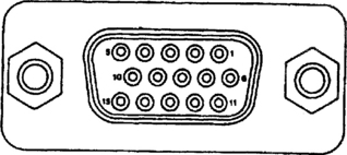
Satellite receivers without integral descramblers often have a connection socket for a separate card reader/descrambler, taking the form of a SCART socket or the 15-pin D-type connector system shown in Fig. 4.18.
MAC ENCODING
The signal parameters, bandwidths and colour-encoding systems discussed in the previous chapter, and adopted for most satellite transmissions in the late 1980s, were developed in the fifties and sixties specifically for use with terrestrial transmissions and in bands and channels already in use for a.m. TV broadcasting. In those times the overriding requirement was to achieve compatibility and reverse-compatibility with black and white transmissions. Most of the constraints within which the NTSC committee, Henri de France (SECAM) and Walter Bruch (PAL) had to work have disappeared with the virtual demise of monochrome receivers and the advent of transmission media like spacecraft and fibre-optic cables. Developments in technology have been many and great in the intervening decades, and as TV screens get bigger and viewers more discerning, the shortcomings of existing systems have come sharply to the fore. Chief amongst them are cross-colour, in which spurious blue/yellow and red/green herringbone patterns appear superimposed on fine picture details; cross-luminance, where sharp transitions in the chrominance image are accompanied on screen by a moving luminance dot-pattern; and a shortfall of definition in both luminance and chrominance components of the picture due to the need for response filtering in both channels to avoid excessive mutual interference.
Several new analogue encoding systems have been devised for picture transmission and recording, and where they are for exclusive or closed-circuit use there is freedom to tailor the system to suit the transmission or storage medium and the signal parameters in use. Where a broadcast system is involved, however, the requirements are very stringent: the receiving and decoding equipment must be cheap, non-critical and capable of good performance; the system must preferably be capable of evolution and upgrading without losing compatibility; it must take full account of current and future technology since it will be very long lived once entrenched in domestic receiver hardware; and the performance of the system must be the best possible within the constraints of currently available channel bandwidth, transmission and reception systems and picture-display techniques. The MAC (Multiplexed Analogue Components) system fulfils these requirements, and combines a digital sound system with an f.m. analogue picture transmission. These factors permit fault-free reception at much lower signal levels: whereas about 40 dB S/N ratio is required for good reception of a.m. TV transmissions, a C/N ratio of less than 12 dB suffices for MAC broadcasts from satellites and along cables.
The composition of a MAC signal is shown in Fig. 4.19. Its main difference from conventional (real-time) encoding and transmission systems is its use of time-compression, calling for memory banks at both ends of the signal link for short-term storage of audio, chrominance and luminance signals. In conveying a CCIR 625-line 50 field colour signal the overall time taken for one TV line must be 64 μs, but here this period is divided into four distinct time slots as Fig. 4.19 shows: a data period containing digital information on sound, teletext, identification and synchronisation; a clamping period at zero level for system stabilisation; a frequency-modulated chrominance signal conveying U and V information on alternate lines; and a long period of luminance information, also frequency modulated. The luminance signal is time-compressed in the ratio 3:2, and the chrominance signal in the ratio 3:1. Digital data is conveyed by PSK (Phase Shift Keying) in which logic 1 corresponds to a phase change of +90°, and logic 0 to a phase change of −90°.
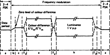
The principle of PSK is fully explained in Chapter 9. The sequence of the MAC line in Fig. 4.19 in detail is as follows:
(a) 206 bits for synchronisation, sound and data, made up of 1 run-in bit, 6 bits of line sync word, 198 bits of data (in two subframes of 99 bits each) and 1 spare bit.
(b) 4 clock periods as transition from end of data, including the leading edge of a pedestal added to the signal to provide energy dispersal.
(c) 15 clock periods at 500 mV for clamping purposes.
(d) T1 10 clock periods, to include a weighted transition to colour-difference signal of 5 clock periods.
(e) 349 clock periods for f.m. colour-difference component, either U or V.
(f) T2 5 clock periods for weighted transition between colour-difference and luminance signal.
(g) 697 clock periods for f.m. luminance component.
(h) T3 6 clock periods for weighted transition from luminance signal.
(i) 4 clock periods for transition into data; includes trailing edge energy-dispersal pedestal signal.
MAC decoding
The MAC signal leaves the satellite transmitter as an f.m. carrier with a frequency around 12 GHz and a bandwidth of 27 MHz. At the receiver the digital data is gated to a PSK demodulator and thence to a decoder which produces sound, data, sync, text, conditional access and control information. The chrominance and luminance components are gated to line-stores, to be read out at normal scanning rates and recombined as part of the decoding process.
DIGITAL RADIO SYSTEMS
Some analogue satellite transponders convey digital stereo radio channels as well as the analogue f.m. vision and sound carriers. A spectrum diagram for the demodulated signal is shown in Fig. 4.20, where the sound carriers are shown in detail: (a) represents the normal arrangement of analogue sound carriers while (b) illustrates the same region carrying twelve subcarriers phase-modulated with digital sound data. Each carrier contains a digital stereo L-R pair, using quadrature phase shift modulation (QPSK) very similar to that which will be described for Nicam sound in Chapter 9. The main stereo analogue-f.m. carriers at 7.02 and 7.20 MHz are retained for compatibility with existing receivers. This configuration provides a maximum of twelve carriers (hence stereo radio channels) alongside a TV channel, or 48 carriers spaced between 0 and 9 MHz if the transponder is given over completely to digital radio.

Fig. 4.20 (a) Analogue-f.m. and (b) digital stereo sound carriers accompanying an f.m. satellite picture transmission. A is an analogue mono carrier, B an analogue stereo (L or R) carrier, C a ‘service’ carrier, and D a digital carrier
Sampling frequency for the baseband audio signals is 48 kHz at 16-bit resolution, affording a level frequency response from 20 Hz to 20 kHz; dynamic range and signal/noise ratio exceed 90 dB, a specification as good as the audio CD system. Pay channels are scrambled according to the CCITT V.35 specification, and can be reassembled by a decoder and subscription smart card. The parameters for digital satellite radio are given in Table 4.3. An outline of a digital radio set for satellite use is shown in Fig. 4.21. The left-hand side of the diagram is virtually the same as for a conventional satellite receiver, while the right-hand side has something in common with the digital outfits we shall examine in Chapter 12.
Table 4.3
Specification of digital radio system from ’analogue’ satellite transponder
| Audio frequency range: | 20 Hz–20 kHz |
| Sampling frequency: | 48 kHz |
| Dynamic range: | 90 dB |
| Audio coding: | ISO/IEC 11172–3 Layer II (Musicam) |
| Stereo channels: | Up to 12 above video, 48 with full transponder use |
| Modulation: | Differential QPSK |
| Data rate: | 192 kbits/sec (including ancillary data at 9.6 kbits/sec) |
| Protection: | CRCC for data and scale factor |
| Bandwidth: | 130 kHz (between −3 dB points) |
| Channel spacing: | 180 kHz |
| Threshold: | 9.5 dB carrier-to-noise ratio with 26 MHz bandwidth |
| Scrambling: | IDR/IBS implementation of CCITT V.35 |
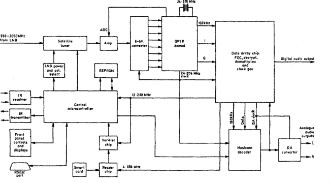
The tuner is governed in normal fashion by the microcontroller and the remote control handset, with tuning data stored in an EEPROM. The 2nd i.f. signal, bandwidth-limited to 27 MHz by a SAW filter like that shown in Fig. 3.6, is demodulated to baseband within the tuner module and passed out to an a.g.c.-controlled amplifier. Thus regulated, it goes to an 8-bit converter and phase-demodulator which selects the required carrier signal to produce four output feeds: I (in-phase) and Q (quadrature) carriers; 192 kHz bit-clock pulses; and 24.576 MHz clocking pulse train. They pass into the gate-array IC, custom-designed for this application, where error-correction, decryption and demultiplexing is carried out. Its main products are the data, bit-clock and DAC clock pulses to the Musicam decoder; 4.096 MHz and 12.288 MHz clocks to the smart card reader and verifier system; and a digital audio bitstream for decoding outside the receiver. Data, bit-clock and DAC clock pulses pass on to the Musicam decoder which decodes the audio datastream for final reassembly into L and R analogue signals by the D-A converter. Descrambling depends on an algorithm contined in the user’s smart card, which is read by one chip and verified by a second, using a proprietary program.
Tuning and acquisition of programmes is carried out automatically in digital radio sets in a manner similar to the auto-set-up system described for TV and video receivers in Chapter 22. The entire satellite band is scanned for DR subcarriers. All their data is stored in an EEPROM memory chip so that the user can call them up at will, aided by an electronic ‘labelling’ system contained in the transmitted datastream: it sorts the programmes by category, channel list and ‘favourite’ listing. The search is regularly done to find new programmes and update existing ones.
SERVICING SATELLITE EQUIPMENT
With no high voltages or currents, no thermionic devices and no moving parts, fixed-dish satellite systems should be much more reliable than the VCRs and TVs they sit alongside. In some cases they are, but many designs of sat-box run much hotter than they need to, basically because of cost-cutting designs and inadequately rated components, especially within the PSU section. Indeed it is the power supply section which is most vulnerable to electrical breakdown. Most other faults are associated with the outdoor unit, and many of them arise through poor practice or false economy at the time of installation. The majority of user problems, however, stem not from these, but from what is known in the trade as ‘finger trouble’ (mistuning, incorrect hook-up, random key-selection or twiddling of presets), or a lack of understanding of the operation of the equipment by its owner/user.
One of the most common troubles with a satellite home unit is sparklies, as shown in Fig. 4.8. This is due basically to a poor C/N ratio, and can stem from many causes, most of them associated with the outdoor unit. First check that the tuning is spot on: when it is, there should be an equal mix of black and white sparklies. Next see whether both polarisation groups are affected (unless the system is a DBS type). If only one polarisation group is in trouble, check the polarisation-change arrangements in the receiver: generally a change of LNB supply voltage between 13 V and 17 V, or a change of ±35 mA through a magnetic polariser. In the former case, if the voltage is changing the LNB unit is suspect. With magnetic polarisers a marked change in sparklie-count should be seen as the current is altered by whatever means the receiver affords, or as the polariser cable connections are broken or reversed.
If the sparklies invade both polarities of signal, first carefully examine the whole outdoor unit and downlead for signs of damage, corrosion or ingress of water, foreign bodies etc.; then if necessary check the accuracy of the dish-pointing. With an accurately aligned dish the problem will be due to a faulty LNB, downlead or receiver unit. The most practical course now is a substitution test on each in turn.
Faulty LNBs cannot generally be repaired except by a specialist workshop with precision test equipment, some of which offer a repair/exchange facility to the trade, a cheaper solution than discarding the faulty unit and fitting a new one. Magnetic polarisers, together with the feedhorn of which they are a part, can be replaced separately from the LNB in their rare cases of failure.
Like the LNB, the tuner heart of the receiver, pre-aligned and enclosed in a screening can, is not usually regarded as a serviceable item and must be treated as a ‘module’ for service and repair purposes, though experience has shown that a careful examination inside (for dry joints and the like) can be worthwhile. Before condemning a suspect unit, carefully check its peripheral circuits components and pin voltages/waveforms.
Coming now to the internal electronics of a satellite receiver (Fig. 4.22), it is not usually difficult for an experienced TV engineer to discriminate between ‘r.f.’ (pre-demodulator) and baseband (post-demodulator) faults in both sound and vision sections of a satellite receiver. Such symptoms as sparklies and instability (vision), and hiss and sibilant distortion (sound), come into the first category, while in the second are low contrast, flicker (faulty clamp?) for vision, and incorrect level, hum or one stereo channel missing in sound. With an oscilloscope, multimeter (see Chapter 23) and the manufacturer’s service manual such faults are easily tracked down. Very often what seems to be an internal fault has its origins in the connections, tuning or protocol of the associated TV, VCR or terrestrial aerial system.
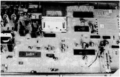
Fig. 4.22 Internal view of analogue satellite TV receiver. Power supply at left, tuner at bottom right, card reader top centre
Control systems rarely fail: where this appears to be the case the key checks, as with TV and VCR equipment, are for supply voltage (Vcc generally +5 V), clock oscillator operation, and reset pulse presence. If all these are correct, confirm that the data lines are not ‘stuck’ by some external cause, and that command data is reaching the microprocessor chip, before condemning it.
It has been suggested earlier that the power-supply section is the most prolific source of true electrical faults within a satellite receiver, and in the case of failure of any sort it is wise to start by checking all internal supply lines. PSUs are fully covered, with trouble-shooting advice, in Chapter 11.
There are now available power-supply repair/overhaul kits for many models of satellite receiver, including replacements for the components which actually fail and those which are likely to have caused their failure, also those (mainly electrolytic capacitors) which are subject to deterioration in use. Use of these kits is recommended for reliable service work. They are available from manufacturers and component distributors.