
SERVO SYSTEMS
A servo system, in the context of domestic electronic equipment, consists in its simplest terms of a movable or rotating load and an electrical drive circuit with two inputs – reference and feedback – and one output. The reference input commands the system, and the feedback input conveys the state or position of the load; the output signal drives the load to the required position or speed such that reference and feedback signals agree; this is called a closed-loop system. The load is now positioned in accordance with the command/reference input, and correction ceases until either the command or feedback inputs change (e.g. motor slowed by additional friction or different speed/position required) when servo output will drive or steer the load to restore the status quo, or meet the new requirements.
Servomechanisms find many applications in consumer service: auto-iris and auto-focus in video cameras; steering and homing-in of satellite receiving dishes; turntable speed and tracking control in audio and video disc players; and the main concern of this chapter, the regulation of tape positioning and transport in a videocassette recorder. These are velocity types which control the speed and phase of a rotating shaft, as opposed to positioning servos which hold the controlled device in a position specified by the input-command signal, e.g. lens and antenna servos. The operation of the latter types is easy to understand when the principles of velocity servos are mastered.
VIDEORECORDER SERVOS
The basic function of the capstan servo is to maintain an even and correct speed of the tape through the video deck; that of the head-drum servo is to ensure that (a) during record the video tracks are laid down on tape according to the appropriate format specification; and (b) that during replay the video head scans are perfectly aligned with their appointed tracks. This latter function can be (and usually is) performed by the capstan servo, whereby the head-drum servo maintains correct video head speed while the capstan positions the tape such that the video tracks are correctly aligned under the head sweep-paths.
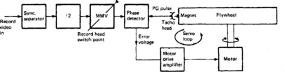
As Chapter 13 showed, it is fundamental to all analogue helical-scan formats that each head enters its scan of the tape just before the arrival of the field sync pulse in the video waveform. This ensures that head changeover takes place at the correct point at the extreme bottom of the picture, and that all the recorded field sync pulses lie in a line across the bottom edge of the videotape ribbon. During record, then, the timing of a tacho pulse (head-position indicator) is compared in a phase detector with that of a 25 Hz (40 ms period) pulse derived from incoming field syncs in a ÷2 stage – the arrangement is depicted in Fig. 15.1. Here the magnet on the flywheel induces one pulse per revolution in the tacho coil – the PG pulse. The servo system drives the motor to the point where reference and feedback pulses are ‘phased up’, and maintains correct phase thereafter. The exact timing relationship between head position and field sync pulses is determined by a pulse delay circuit, and is adjusted to set the head changeover on record to take place seven TV lines before field sync. In practice a little overlap is permitted, and the head actually hits the tape about ten lines before the field sync pulse is written onto the tape.
Phase and speed loops
Video servo systems need two servo loops for optimum control of the head-drum motor: a speed-control loop to rapidly establish the correct rotational rate when starting from rest or recovering from a disturbance; and a phase control loop with high gain and ‘tight’ control to set the correct lock point without hunting or instability. We have already seen how correct phase is established with reference to a tachogenerator on the head drum or in the motor. Speed monitoring depends on a frequency (tone)-generator (FG) built into the motor itself. It usually takes the form of a multi-pole magnetic disc passing over a printed coil, the output frequency of which is proportional to motor speed. This signal passes into a form of frequency-to-voltage converter whose output is also applied to the motor as an error drive, forming a dual-loop servo with separate speed and phase sections as outlined in Fig. 15.2(a). The speed loop quickly brings the drum up to correct speed, then the phase loop takes over to hold the ‘dynamic position’ of the head drum rigidly in accordance with the phase of the reference input. When the speed is incorrect, operation of the phase control loop is not required because its error voltage output is disordered at this time. Similarly the influence of the speed-correction loop is superfluous during the presence of a phase error. The gains of the two feedback loops are arranged to vary according to the motor speed, then, as shown in Fig. 15.2(b): this gives optimum correction performance. Fine adjustment of the delay in the head-drum phase loop in Fig. 15.2(a) sets the head switching point relative to the field sync pulse, and may be set up with a preset resistor, a numerical value set in factory or service shop and held in EEPROM memory, see Chapter 22; or a completely automatic system whose reference point is the off-air (record) or off-tape (playback) field sync pulse.

REFERENCE SOURCES
Since the angular position of the capstan shaft is not relevant in the same way as that of the head drum, there is no intrinsic requirement for a PG on the capstan motor or shaft, and a PG is seldom provided here. For optimum performance of the capstan servo, however, a dual-loop system is often used, with both speed and phase loops working from the capstan FG output. In its most basic form the capstan servo is purely a speed regulator, and so may be ‘paced’ by a stable reference crystal during record, playback or both. It is common practice to use the 4.43 MHz chroma crystal as reference, and count down its output frequency to a rate comparable with the FG frequency; alternatively a dedicated servo reference crystal may be found. Once locked to such a reference the tape speed is regulated with great accuracy, and any momentary speed variations due to changes in tape tension or other factors are rapidly nullified by the servo-feedback system. During record the capstan shaft speed is always locked to some local reference – on playback, capstan control may be more elaborate, as will be described shortly.
Coming to the drum servo, on record the invariable phasing reference (which also sets the speed, of course) is incoming field sync, in order to comply with the one-complete-field-per-head-sweep requirement as already described. During playback there is no external reference frequency to lock to, hence no absolute phasing requirement, unless the videorecorder output is required to lock to another source of video signals for use with a vision mixer or effects console – rare in domestic situations, and difficult to implement with a machine not designed for this genlock feature. In a stand-alone situation, however, line, field (and audio) frequencies must conform closely to broadcast standards to ensure correct timebase locking, and to prevent spurious effects in the TV or monitor. In playback, then, the reference pulses which master picture timing come from a crystal reference, usually the same one as was used for capstan speed control during record. To ensure correct tracking during replay, however, one phase control loop is essential: the control track loop. In V8 format machines the ‘control track’ is read out as part of the video track signal itself; the ATF tone system has already been discussed. In VHS machines the control track is a separate longitudinally recorded series of pulses on tape, used during replay as a positioning reference for the video tracks.
VHS control track
At the time of recording the divided-by-two incoming field sync pulses trigger a flip-flop to provide a 25 Hz squarewave. It is used, as already discussed in this and the last chapter, for head-drum phasing and for head identification in the colour-under circuits. It is also passed to the stationary control-track head, which is part of the audio head assembly, placed about 6 cm ‘downstream’ of the video head-drum exit point. At each change of state of the head flip-flop waveform, i.e. at 40 ms intervals, a mark is made in the magnetic pattern of the control track. Because the head-drum to control-head spacing is standardised, each of these marks will be made on the tape in a fixed position in relation to the start points of alternate video tracks. During replay the same control-track head reads out the pulses. By establishing a fixed phase between these and the head-drum PG pulses a relationship is set up between video head positioning and the physical disposition of video tracks on tape – this is what is required for tracking control. On replay, then, a local reference crystal is used to establish correct speed for both head drum and capstan. The error voltage coming from the phase detector comparing control track and head-PG pulses can be applied to either the head-drum motor or the capstan motor. In either case it will establish and maintain a constant head path with respect to the pre-recorded video tape tracks; to make them coincide a suitable delay is inserted into the path of either the control track pulse or the head PG pulse. The delay period can be varied by the user tracking control over (typically) two track widths, corresponding to about 180° of head-drum rotation. This enables the user to set up correct tracking on any tape/machine combination under any circumstances – except those of a faulty machine. The mid-way, ‘auto’ or default setting of the tracking control corresponds to format standard and to a specific drum-to-control-head spacing. It is used during replay of the machine’s own recordings, and those recorded in other correctly set-up videorecorders.
TF replay tracking
V8 format videorecorders have no separate control track as such. The need for tracking correction is indicated by imbalance in the two crosstalk-beat frequencies. As described in Chapter 13 and Fig. 13.7 an error voltage is produced from this, used to directly adjust capstan speed. In this way perfect and automatic tracking is assured, with no need for a tracking control.
PULSE-COUNTING (DIGITAL) SERVOS
The basic function of the electronic section of a videorecorder or disc-player servo system is to measure time (i.e. the period between arrival of reference and sample pulses) in the case of the phase control loop; and frequency (FG rate) for the speed control loop. Both these functions can be carried out with great speed and accuracy by means of digital counter/timer circuits using a crystal clock as a basic ‘metronome’.
An arrangement for a digitally based phase control servo is given in Fig. 15.3, in which the crystal clock on the left produces 1 μs-interval pulses. The input reference pulse is used to enable counter 1, which commences to count clock pulses from 0000000000 upwards. In this 10-bit counter the maximum count is 210, which corresponds to decimal 1024. At the clock rate of 1 MHz the counter will take about 1 ms to reach maximum count. Before this happens, however, a sample pulse appears and activates the latch, which effectively ‘freezes’ the count at that instant and transfers it to the hold register of a digital comparator. If the sample pulse comes 500 μs after the reference pulse the count will have reached about 512 (binary 1000000000). The latch operates and binary 512 is loaded into the comparator as an indication of the time lapse between the arrival of the two pulses.
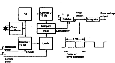
Now consider the upper section of Fig. 15.3. On emergence from the ÷2 stage the clock pulses are at 500 kHz, 2 μs intervals. They are fed to a second 10-bit counter (counter 2) which also counts from zero to 1024, resetting itself each time it fills up. The count-and-reset process for counter 2 is continuous, and because it is counting 500 kHz (2 μs period) pulses it resets at 1024 × 2 μs = 2 ms intervals. At each reset a trigger pulse is applied to the set input of an SR bistable, whose output is thus set high. The continuous count made by counter 2 is also fed to the comparator which is designed to detect coincidence between the binary numbers in its ‘hold’ and ‘compare’ registers. After 1 ms, counter 2 will have reached 512 so that the counts in the two comparator registers match. Under these circumstances the comparator output goes high; this pulse is passed to the ‘R’ input of the SR bistable, resetting its output low. The bistable is being set and reset at 1 ms intervals to give an output whose mark/space ratio is 1:1.
Suppose the motor speeds up. The sample pulse will come early, giving counter 1 little time to accumulate a count before the latch operates. A correspondingly low number, say 256, is loaded into the hold register of the comparator. Counter 2, having set the SR bistable high when it passed zero, will take only 500 μs to accumulate a count of 256 to satisfy the comparator and reset the bistable low again. It will remain low for 1500 μs (1.5 ms) before being set high once more by counter 2 passing zero. The mark/space ratio of the bistable output signal is now 1:3. The opposite applies if the motor slows down for any reason. Whereas the rising edges of the bistable output waveform always occur at 2 ms intervals (see Fig. 15.3) due to the regular resetting action of counter 2, the timing of the falling edges is determined entirely by the time lapse between reference and sample pulses.
The pulse-width-modulated (PWM) squarewave output is converted to a d.c. error voltage by passing it through an RC integrating filter. The output from this is used to modify motor speed.
Digital speed correction
The arrangement of Fig. 15.3 is fundamentally a measurer of time. In order to use it in a speed-control loop some modification is required, as shown in Fig. 15.4. Waveform a is the FG tone, amplitude-limited to produce squarewave b. Its rising edge triggers a short monostable to produce pulse train c; its falling edge triggers a second monostable whose output is pulse train d. Each pulse ‘c’ enables counter 1 and each pulse ‘d’ resets the counter and operates the latch. The latch count is inversely proportional to FG frequency, and is held in the comparator’s hold register until counter 2 (whose configuration and function are the same as in Fig. 15.3) reaches the same count, whereupon the bistable is reset. The varying M/S ratio is processed as already described, and now produces an error voltage which reflects the frequency of the FG input signal. For this speed control application the bistable set/reset rate is required to be faster than the 1 kHz rate typical of a digital phase corrector, and an output rate between 4 and 17 kHz is general. In either case the bistable rate is determined by the clock rate and the number of bits (maximum possible count) of the recirculating counter – counter 2 in the present Figs 15.3 and 15.4. These are chosen to suit the sampling rate to the application loop in which it is used.
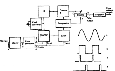
Fig. 15.4 Digital servo arranged for speed control; compare with Fig. 15.3
In some videorecorder designs the counter bit capacities and clock rates vary with different loop requirements in drum and capstan servos. Advanced designs also incorporate a ROM in the digitial servo chip to provide different counting conditions for varying deck conditions, i.e. SP/LP operation and ‘trick-speed’ replay modes; the ROM is addressed by a mode select line whose origin is the user’s function keyboard.
PRACTICAL SERVO SYSTEM
Fig. 15.5 shows a digital servo arrangement for a dual-speed VHS homedeck videorecorder. The basic reference for capstan speed is the crystal-generated fsc clock entering at pin 35. It is compared with FG feedback (via pin 31) to produce a control voltage at IC pin 20. During playback capstan phasing is governed by control-track pulses off-tape, with user and autotracking control effected via the I2C bus at IC pins 44 and 45. In record mode the CTL head is fed with pulses at 40 ms intervals via IC pins 22, 23 and the CTL divider within the chip; the duty-cycle of the pulses is briefly changed from 60:40 (normal) to about 30:70 at the beginning of each new recording to form an index mark for programme location.

During record mode the starting point for the control track signal and the drum (here called cylinder, CYL) phase control is the sync pulse entering the IC on pin 42. In conjunction with the PG (TACHO) pulse entering on pin 55 and the FG tone coming in on pin 1, it produces a speed/phase control voltage at IC pin 4 for application to the motor control chip IC01. The servo chip produces at its pin 38 an SW25 squarewave for monitoring within the system-control section and for use in the head-amplifier and colour-under sections of the signal circuits, together with a VP (Vertical Pulse) to take the place of the corrupt field sync pulse during still-frame and ‘trick-play’ modes. All functions of the IC, including headswitch timing, are governed by the I2C serial control bus linked via IC pins 44 and 45.
In many VCR designs the servo system is incorporated in the system-control chip: an example is given in Fig. 16.3 on page 330.
TILTING DRUM TECHNOLOGY
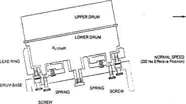
While a wide-head design can give excellent still-frame picture reproduction, playout of ‘search’ pictures in forward and reverse directions always gives rise to noise bars across the picture in conventional videorecorder designs – it is the inevitable result of multiple track crossings by the replay heads, as described on page 280. To overcome the problem JVC designed a tilting head drum (Dynamic Drum, DD System) in which the entire drum assembly is canted, under servo control, to align the head sweeps with the tape tracks in search-forward and reverse-play modes; the effect and results are shown in Fig. 15.6, while Fig. 15.7 gives an idea of the working of the drum-tilt mechanism. In the rest state (record and normal-replay modes) the underside of the lower drum rests on four fulcrum points. To tilt the assembly, the screws are rotated together by a motor so that the lower drum rests on two fulcrums whose individual heights are governed by the screw settings, and set by a servo loop whose reference is the off-tape video-f.m. signal. The total movement is measured in microns only, and has great precision and stability.

Fig. 15.6 Search modes: (a) the multiple track-crossings ordinarily involved in picture search forward and backwards, with (b) the off-tape waveform which gives rise to noise bands across the picture. Diagram (c) shows how the dynamic drum realigns the video head sweeps to give (d) a noiseless off-tape waveform and a ‘clean’ picture
MOTORS
For reliability and versatility it is common practice to provide direct-drive motors for head drum and capstan, in which the motor shaft carries the drum itself or forms the capstan respectively. These brushless motors have built-in FG generators and a multi-pole drive stator, around which rotates a multi-pole magnetised ferrite disc or cup. A typical arrangement is shown in the circuit diagram of Fig. 15.8. The motor itself is on the right, and contains three main coils split into six poles; an eight-pole rotating ring magnet; and three Hall ICs which are solid-state magnetic-field detectors. The drive circuit in IC2006 switches current into each coil in turn at 120° intervals. In this way, one coil-pair at a time will pull the ferrite disc round while a second coil-pair pushes it, the third being inactive. The sequence of coil-switching is controlled by the three rotor-position-sensing Hall ICs built into the stator assembly, and currents flow in both directions through the stator coils. To avoid flutter in motor speed due to any imbalance in coil currents or fields, the sampling resistor on pin 2 of IC2006 continually monitors motor current, passing in turn through all six coil halves. Any changes are compensated for by feedback to the torque control input at IC pin 20.
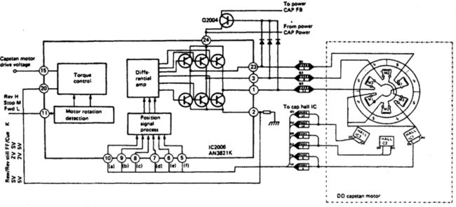
Motor control and switching is also carried out within IC2006. A speed control voltage (basically dependent on the error voltage from the servo circuit) enters on pin 15, where a falling potential will drive more current through the switching transistors and stator coils to accelerate the motor. Reverse, stop and forward commands from the system control block enter the IC on pin 11, where they are decoded in the motor rotation detection block.
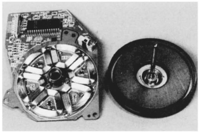
A photograph of a direct-drive motor of this type appears in Fig. 15.9. This design is particularly flat and compact.
SERVO OPERATION IN SEARCH AND STILL MODES
VHS-LP operation involves identical tape and capstan speeds during record and replay, and has little effect on servo operation: the capstan runs at half normal speed, easily arranged by introducing a ‘×2’ factor in its speed-control loop, or changing counting rate in the speed-control circuit. Where separate head-pairs are provided, the head-drum phasing must be altered to accommodate the difference in the physical positioning of the SP and LP heads on the drum. It is in such ‘trick’ replay modes as still-frame and picture search (cue and review) that servo operation is modified.
In any situation where the tape speed during replay is different to that during record, the angle of the head scan across the video tracks changes, giving rise to horizontal noise bars in the picture at each track-crossing and (especially in cue and review modes) a change in the number of lines per TV field. Non-standard line timing can cause misregistration between luma and chroma components on the TV screen, and loss of line hold if the error exceeds a few per cent. To prevent these effects speed compensation is applied to the drum motor – it is speeded up in cue mode and slowed down during review. These speed offsets are provided by ROM-controlled counter programming.
Trick-speed operation, then, mainly concerns the capstan servo. For cue or review the system control section sets the motor direction according to the command keyed in by the user, then capstan speed is increased by a factor of three or more. To lock the resulting track-crossing noise bars stationary on screen, capstan phase control is referred to suitably divided off-tape control-track pulses.
For still-frame operation the capstan is stopped. In simple videorecorders this will leave a mistracking bar at some random position on the TV screen. For noise-free still frame the capstan stopping point is under close control, determined by the relative positions of the 25 Hz head flip-flop waveform and the noise bar in the replay f.m. envelope. Correct phasing of these two ensures (in conjunction with the wide-head system described in Chapter 13) that the noise occupies the field blanking interval where its effect is nullified by the synthetic field sync pulse generated and inserted into the video waveform at this time, as already described. In some machines the capstan stop-and-shunt motor drive waveforms are generated and timed by a purpose-designed chip, or a microprocessor with suitable built-in ROM. Frame-advance facility is also provided in these cases, for which the capstan motor is stepped on by one track-width for each touch of the advance button, while the position of the noise bar is monitored and corrected each time. Slow-motion is a development of this technique, whereby the capstan motor steps forward very rapidly at short intervals under the control of off-tape control track pulses. New and correctly aligned video tracks are thus presented in the path of the video head sweeps, each remaining in position for many revolutions of the drum before the tape is smartly advanced to display the next field.
SERVO AND MOTOR FAULT SYMPTOMS
A fundamental point to remember in servicing servo and motor circuits is that capstan-speed faults will upset sound reproduction from the (mono) longitudinal track to give wrong pitch, wow or flutter – picture tracking will also be affected. Head-drum speed fault symptoms are confined to the picture; wow and flutter here gives rise to a lateral wobble of the picture, which will break into horizontal lines if drum speed deviates far from the norm. Loss of the reference signal (i.e. PAL or local crystal oscillator stopped) will usually greatly increase motor speed, and in many designs loss of feedback signal faulty FG or PG generator, for instance – will do the same. In the case of a fast-running head drum, it can be slowed by friction from a finger to check for correct line frequency at normal speed; at the same time the effect on feedback signals (and their influence) can be monitored. If continuity is present, they should be acting to drive the motor faster, and the diagnosis then consists of finding out why the motor is not responding to the ‘turn-down’ signals being developed at excessive motor speeds.
A head or capstan motor running at the correct speed, but whose phase control loop has failed, will drift in phase to give the following symptoms. Head servo out of control on record – head-switching point disturbance drifts up or down screen: check for 25 Hz head PG and field sync pulses. Head or capstan servo out of control on playback – cyclical tracking errors in which part or all of the screen is affected by noise: check PG pulses, tracking delay system, and particularly the control track pulses from the stationary head. A worn, dirty or misaligned control head will pick up insufficient pulse amplitude to operate the servo. This malfunction is often masked by the action of a muting circuit, which only unblanks video signals when the servo is locked up: the idea is to prevent unstable pictures being displayed.
In general the electrical components of a servo system are much more reliable than the mechanical components. First checks, then, should be for the presence of reference and feedback signals, which depend on crystals, plugs, sockets and transducers – in magnetic and optical form – and on transfer of control pulses to and from tape. Motors, belts and bearings are also high on the suspect list, though brushless direct-drive motors have a lower failure rate than their early permanent-magnet brush-and-commutator counterparts, still sometimes encountered and still widely used for the more mundane deck functions such as tape- and cassette-loading and reel drive.
Once the mechanical components have been exonerated, the fact that both speed and phase correction sections are closed loops is a considerable aid to fault diagnosis. A fault condition implies that the loop is broken, and at the ‘severed end’, as it were, a strong corrective signal will appear in an attempt to restore normality; it is upon tracing this that the diagnosis should be concentrated.
Setting-up procedures for servos (especially in trick playback modes) vary widely with machine type, age and manufacturer. Except in simple machines with few presets and obvious functions no attempt should be made to diagnose faults in the servo circuits without the manufacturer’s service manual and all necessary instruments. More on test equipment and diagnosis procedures will be found in Chapter 23.