COMPONENTS AND ASSEMBLIES
All electronic equipment uses components, passive (R, C, L and some diodes) and active (transistors, ICs etc.), built up into assemblies to make complete operational units; some units, like the videorecorders and disc players examined later in this book, have mechanical assemblies as well. This section surveys the most common building blocks in electronic systems. Type-coding and formulae are given in Chapter 24.
RESISTORS
The basic function of a resistor is to impede the passage of an electrical current, absorbing energy and dissipating it as heat. The vast majority of resistors in use dissipate less than 500 mW, and the most common are metal-oxide and metal-film types, which (due to their superior accuracy and stability) have superseded carbon composition types. Metal-film resistors have low inherent noise and high stability, and are available in a wide range of values and sizes. Metal-oxide types have better power-dissipation capabilities, and are generally based on the resistive properties of stannic oxide, SnO2.
Wire-wound resistors are used for higher-dissipation applications, from about 2 W upwards – as equipment becomes more efficient, high-power resistors are being ousted, along with the unwelcome heat they generate. Wire-wound resistors can be made to close tolerances and high accuracy, and thus find ‘precision’ applications – in test equipment, for instance.
Other types of resistor are: metal glaze, whose characteristics are high resistance in small sizes, and resistance to external heating; Cermet, with similar virtues; and thick-film, made by screen-printing a carbon-loaded ink onto a substrate, and, typically in the form of ‘packages’, incorporating several resistors for non-critical applications.
There is a wide range of non-linear resistors for special applications. Amongst the most common types are VDR (Voltage Dependent Resistors), whose value depends on applied voltage, and thermistors, whose resistance varies with temperature. They are usually made of manganese oxide or nickel oxide, giving the thermistor a negative (falling resistance) reaction to heat, either externally supplied or generated internally by the passage of current.
Variable resistors have some form of conductive wiper which can be set to any point on the resistive track, and in domestic equipment these range from large double-gang volume controls to tiny PCB-mounted presets. Their tracks are carbon-coated or carbon-suffused, and may have a linear, logarithmic (volume controls) or other relationship to the physical position of the slider. In many cases variable resistors are being superseded by ‘software-control’ from microprocessor ICs.
Fixed resistors are available in various logarithmic series of standardised values, designated E12, E24, E96 etc., the number indicating how many different values are available in each decade. The standard range is E24: 1.0, 1.1, 1.2, 1.3, 1.5, 1.6, 1.8, 2.0, 2.2, 2.4, 2.7, 3.0, 3.3, 3.6, 3.9, 4.3, 4.7, 5.1, 5.6, 6.2, 6.8, 7.5, 8.2, 9.1 and their decades.
CAPACITORS
A capacitor consists basically of two conductive plates separated by an insulator (dielectric). It has the ability to store a charge of electricity, proportional to its capacitance, which for general use may range from 1 pF to 10 000 μF, and may be more for special applications like clock back-up stores in videorecorders. Capacitors are broadly divided into two classes, non-polarised and electrolytic.
The first category has a dielectric typically of ceramic or plastic-film material. Ceramic capacitors are formed by evaporating metal electrodes onto a ceramic insulator, and can take many physical forms: tube, disc, plate and multilayer. With different ceramic types, characteristics like temperature coefficient, physical volume and capacitance can be traded off. Plastic-film capacitors are generally larger than ceramic types for the same electrical ratings; they have metal-foil or metal-film electrodes and dielectrics of polyester, polystyrene, polypropylene or polycarbonate. With their relatively large physical volume and dislike of high body temperatures during soldering, film capacitors do not lend themselves to modern PCB techniques as well as ceramic types.
Electrolytic capacitors have the highest capacitance per unit size, and are generally used in values above 0.1 μF. They depend for their operation on a very thin oxide film formed on the surface of the positive plate by electrolysis when a d.c. polarising voltage is applied. There are two basic types of electrolytic capacitor: aluminium and tantalum. Aluminium types are available in higher capacitance ranges than tantalum, and are commonly used as PSU reservoirs and for smoothing and decoupling on supply lines. Tantalum capacitors are marginally less reliable, but have a size advantage (smaller) and higher permissible operating temperature.
Variable capacitors are now rare, except in varicap diode form, described below.
INDUCTORS
Inductance concerns the magnetic properties of a current-carrying conductor; all conductors are surrounded by magnetic fields. Practical inductors concentrate the magnetic field by winding the conductor into a coil with (usually) a magnetic core of ferrite or laminated iron. A basic property of an inductor is its ability to turn electrical energy into magnetic energy and vice versa. Examples are solenoids, relays, recording heads and loudspeakers in the one case, and replay heads, ferrite-rod aerials, phono pick-ups and VCR-motor PG/FG generators in the other. Transformers convert an alternating current into a strong, ‘tight’ magnetic field which induces a current in the secondary winding, usually at a different voltage: transformation ratio is proportional to wire-turns ratio.
The size of an inductor, for practical purposes, is generally proportional to the current it carries, and inversely proportional to the frequency at which it works. In conjunction with capacitors, inductors can form resonant circuits, the formulae for which are given in Chapter 24. The unit of inductance is the henry, which is too large for most purposes: millihenries (mH) and microhenries (μH) are more common terms. Because of the relative cost, size and complexity of inductors they are avoided where possible in modern design; in low-power applications they have been largely superseded by, for example, ceramic filters and ‘electronic’ substitutes.
DIODES
The diode is the simplest form of semiconductor, and consists of a single PN junction with the basic characteristic of conducting in one direction only. Most general-purpose diodes are based on silicon, with a forward voltage drop of about 700 mV and a very high reverse resistance.
In TV and video applications there are many significant variants of the diode. Some of the most important are: the zener diode, which has a specific and (with limited current) non-destructive reverse breakdown voltage, used as a reference; the varicap diode, always operated in reverse-bias, with an effective capacitance dependent on applied voltage; the light-emitting diode, LED, which emits infrared or coloured light proportional to its forward current; the PIN diode, used as a modulator, switch or attenuator in UHF and SHF applications; laser diodes, allied to LEDs, but capable of producing high-intensity, spectrally pure beams of light; and photodiodes, whose conduction depends on the intensity of light falling on the junction.
TRANSISTORS
A transistor is a semiconductor device whose output can be controlled by the signal applied to one or more input electrodes, in the form of current in the base-emitter junction (bipolar type) or voltage at the gate (field-effect type). Most transistors are based on silicon, and have three terminals, base/emitter/collector or gate/drain/source. Basically transistors are classified by their semiconductor material (germanium, Ge; or silicon, Si) and their polarity (PNP or NPN). Within these categories there is a very wide range of types: general purpose, for linear or switching applications up to about 3 MHz at about 500 mW dissipation; power devices, typically used in audio amplifier output stages, whose main characteristic is an ability to dissipate heat; high-voltage types, for, for example, RGB output stages driving picture-tube cathodes, and (combined with high power capability) for PSU switching and line deflection; high-frequency devices with short transit times and often low-noise characteristics for use in VHF, UHF, and SHF front-ends; low-noise types for amplification of very small baseband signals; Darlington pairs which give very high power gain; switching transistors for fast pulse or logic signal handling; and complementary pairs, matched NPN/PNP devices generally used for audio class B power amplification. These categories are the main ones encountered in TVs and VCRs.
INTEGRATED CIRCUITS
Most of the components described so far (but primarily semiconductor devices) can be formed on a silicon wafer substrate in subminiature form with very high density to form integrated circuits (ICs), whose advent and development is alone responsible for the very advanced state of consumer electronics, and the low – in real terms – cost of equipment.
ICs fall into two main groups, analogue and digital, with many subdivisions in each. Analogue ICs used in TV and video sets are almost invariably purpose-designed for the role they play: field timebases, PAL decoders, audio power amplifiers and scan-timing generators in TV sets; f.m. modulators/demodulators, colour-under processors, motor drivers and audio record/playback amplifiers in VCRs; and power-supply regulators, i.f. amplifiers and video demodulators/amplifiers in both. High-power IC amplifiers, usually driving ‘magnetic’ loads, have heat sinks and can provide powers up to many tens of watts.
Digital ICs have a huge variety, and most of those used in home-entertainment equipment fall into these four classes: general-purpose chips, containing relatively simple counting, logic and switching functions, used as ‘building blocks’ of a system; microprocessors, generally used for overall control and co-ordination of the functions of a complete unit, many of which are mask-programmable to suit specific products, with the ‘software’ denoted by a suffix to the type number; peripherals, which typically interface microprocessors to other devices like display panels, memory chips and data buses; and memories, which can be as simple as a 1Kbit RAM for tuning data storage or as complex as a 2Mbit DRAM capable of holding a complete TV field in digital form. Many ICs are static-sensitive: see static precautions in Chapter 23.
FUSES
Fuses and fusible devices are essential for protection against overheating, damage, fire and shock. The most common type of fuse is the 20 × 5 mm glass type, which comes in five classes, TT, T. M. F. and FF, in ascending order of operating speed (See Fig. 1.1). Glass fuses are available in current ratings from 32 mA upwards, the rated current being the one which the fuse can carry continuously without degradation. To blow the fuse a much higher current must be passed for a period depending on the ‘time’ rating of the fuse. This minimum fusing current is typically 50–100% more than the rated current. All fuses have internal resistance and hence a voltage drop while in operation; fast fuses have higher resistance than delay types, and a drop of 1 V across an HBC fuse rated at (and carrying) 500 mA is normal. Delay fuses are used where inrush or transient currents are expected to significantly exceed the normal steady-state current.

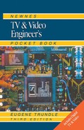
ICP (Integrated Circuit Protector) fuses are commonly used in consumer equipment. They are plastic-encapsulated in the shapes shown in Fig. 1.2. They are fast-acting (200 ms at 300% current) and non-polarised, with low voltage drop and low (50–150 V) voltage ratings. The figure following the type letters must be multiplied by 40 to give the rated current in milliamps: thus an ICP-N15 is a 600 mA and an ICP-F10 is a 400 mA type.
PRINTED CIRCUIT BOARDS
PCBs are the basis of virtually all electronic assemblies. A PCB consists of a substrate of SRBP (Synthetic Resin-Bonded Paper) or epoxy-bonded glass fibre, 1–2 mm thick, with a network of copper conductors, about 35 microns thick, ‘printed’ on its surface. The copper pattern has lands or pads aligned with the legs and leadouts of the components, which both secure them and connect them to the board. Conventional PCBs have all the components on one side, and the printed pattern on the other, with all the legs and leadouts passing through holes in the board. A later development uses a print-through-holes technique, which permits higher-density packing by virtue of having conductors on both sides of the board. In domestic products SRBP boards are conventionally used for economy. They have a lower operating temperature (85°C) than fibre boards (120°C) and a risk of carbonisation under fault conditons, which can render the board conductive.
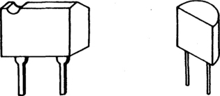
A variant of PCB technology is the surface-mounting (SM) assembly, in which subminiature components and printed conductors share the same surface, permitting both sides of the board to be densely covered. Through-board links provide interconnections as necessary. SM assemblies have many advantages for the manufacturer and user: their high-frequency performance (e.g. in tuners) is good; and they offer very high packing density (tiny but complex products) and consistent and reliable performance. The components have to be able to withstand solder-flow temperatures, and must be very accurately placed on the board during manufacture. All components, active and passive, are available in SM versions, and resistors and capacitors are typically 2 × 1.25 mm outline. Value-coding for these devices is listed in Chapter 24, and Fig. 1.3 gives an example of the use of SM PCBs in a consumer-market camcorder. Practical advice on servicing PCBs and SM devices is given in Chapter 23.
SOLDER
Most electrical joints, on PCBs and elsewhere, are made with solder, which for general purposes is a 60/40 alloy of tin and lead with a melting point around 183°C. For applications where operating temperatures may approach this, high melting point (HMP) solders are available. Solders are generally prepared in wire form with one or more internal cores of non-corrosive flux. For general servicing purposes 18 or 22 s.w.g. is suitable, though finer grade (26 s.w.g.) is useful for fine work and for rework of SM PCBs. Special-purpose solders also relevant to these are various preforms, and solder paste, in which tiny globules of solder are suspended in a semi-liquid flux and dispensed onto the board as required during manufacture or repair, in the latter case from a syringe. All soldering is accompanied by fluxing, the application of an agent (e.g. resin) to remove oxides from the surfaces of both metals to be bonded.