
VIDEO DISC TECHNOLOGY
Video-recorded discs have never enjoyed the popularity of videotape cassettes for several reasons, among which are the fact that (with the exception of advanced DVD types) it is not possible to record on them at home; even though they are cheaper to produce in bulk, they have tended to be more expensive in the shops than tape; and software availability is not as good as for tape. On the credit side they give much better, more detailed pictures than everyday videotape formats, and they do not wear because their play process is a contact-free one. Because of their picture and sound replay quality video disc players find their best market among home-cinema enthusiasts, many of whom import discs from the USA (where there is a wider choice of films and a different censorship scheme) and take advantage of the multistandard capability of most LDV players and many TV sets.
LASERVISION
Laservision is the longest-established optical video disc system, having started in 1972 with Philips. It offers virtually full-broadcast bandwidth, and is the only home video system capable of handling an analogue colour signal en-suite as it were: conventional videocassette formats require the chroma subcarrier to be frequency-shifted in a colour-under system, and low-band ones (standard-VHS and Video 8) are limited to about 2.5 MHzluminancebandwidth. For Laservision the vision and sound information is encoded on the disc in the form of a series of tiny pits in its surface, which is then aluminised and sealed with a coat of plastic. Ordinary video discs are 30 cm (12 inches) in diameter, and double-sided. The signal-bearing pits are arranged in a continuous spiral, starting near the disc centre and finishing at the outside edge. They are very closely spaced at around 600 lines per mm, giving a total track length of about 34 km, 21 miles.
The readout system is optical, and the pick-up sensor does not touch the disc at all – it depends on reflections from the pitted surface. Thus there is no wear or deterioration of the disc, even in still-frame. Since the optical system focuses on the subsurface pits, dust, fingerprints and (within reason) superficial damage to the disc surface have no effect on reproduction quality. The specifications and characteristics of the Laservision system are given in Table 20.1.
Table 20.1
Specifications for Laservision system
| Disc material | Aluminised plastic |
| Disc diameter | 200–300 mm |
| Disc thickness | 2.7 mm |
| Centre hole diameter | 35 mm |
| Rotational rate | 1500–570 r.p.m. |
| Fields per rev. | 2–6 |
| Recorded band | 107–290 mm |
| Sides | 2 |
| Duration per side | 30–60 min |
| Reading light | 1 mW laser |
| Tracking system | Optical servo |
| Recorded signal | 6.76–7.9 MHz |
| Luminance bandwidth | 5 MHz (−6 dB) |
| Chrominance bandwidth | 500 kHz |
| Video S/N ratio | 37 dB |
| Audio S/N ratio | 60 dB |
| Audio channels | 2 |
| Audio carriers | 684 kHz and 1066 kHz |
| Audio carrier deviation | ±50 kHz |
| Audio bandwidth | 40 Hz-20 kHz |
| Channel separation | 55 dB |
FIELDS, TRACKS AND MODULATION
There are two ways of arranging the television fields on the surface of the disc, both illustrated in Fig. 20.1. At (a) is depicted the ‘active’ disc in which each TV field occupies one half of the disc’s rotation, with all the field sync pulses lined up across a diameter of the disc. These play at a constant speed of 1500 r.p.m. and have the advantage of excellent trick-speed replay: the pick-up is ‘skipped’ sideways during the field blanking interval for still-frame or special-speed playback. This disc is a CAV (Constant Angular Velocity) type, and since the track-length for 1 field of 312½ lines varies greatly from the middle to the outside of the disc the pit-density is great at the beginning of play, but sparse at the end. CAV discs have 36 minutes’ playing time per side.
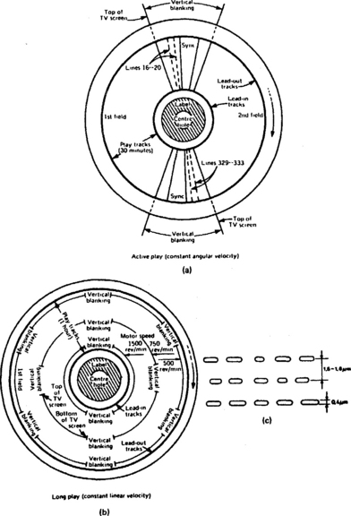
The alternative arrangement is the CLV (Constant Linear Velocity) disc shown at Fig. 20.1(b). Here the pit-density along the tracks is constant so that each TV field has the same track length. At replay start (disc centre) 2 fields are read out per rev at 1500 r.p.m. As playback continues the disc slows down to maintain constant track-scanning speed until at the outer edge the pick-up is reading six fields per rev at about 550 r.p.m. This disc is capable of 54 minutes playing time per side, but no trick-replay is possible.
The pit-track pattern is shown in Fig. 20.1(c). The track pitch is 1.6 micron, the pit width is 0.4 micron and pit depth 0.1 micron. The surface of the disc is scanned by a very fine (0.9 micron) spot of light from a laser, and the information is read out by a photodiode which discriminates between the reflected light level during the presence or absence of a pit. In the absence of a pit most of the light is reflected onto the pick-up diode which passes high current; when a pit is present most of the light is scattered and little returns to the photodiode, whose current is now low as a result. The diode output contains all the video, colour and sound information.
LIGHT PATH
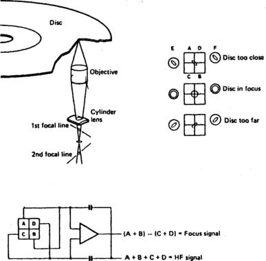
The Laservision disc does not have a turntable as such – it is clamped at its centre and scanned from below. Fig. 20.2 shows the light path of one type of pick-up which is suitable for both CD-audio and Laservision (CLD) players. The laser diode emits a narrow beam of infra-red light whose wavelength is 780 nm. The first component encountered by the light beam is a grating, a glass plate with horizontal lines etched into it. Here the light beam is split into three by a process of diffraction: a bright central one and two secondary beams of lesser intensity. The three closely spaced beams are now turned through 90° in a half-mirror, which has the characteristic of reflecting half the light presented to it and admitting half of it, the latter property being used for the reflected beam as we shall see. Next on the light path comes a collimator lens whose job is to capture the diverging light beams and set them on a parallel path towards the reflective mirror which turns the beams through 90° to direct them to the objective lens. This precision component focuses the three light beams to sharp pin-points of light on the surface of the video disc. The diameter of the focused central spot is less than 1 micron, which is comparable with the wavelength (0.78 micron) of the lightwaves themselves. The outer light spots are used for tracking purposes, and the central one to read out the information on the disc surface.

Fig. 20.2 Light path in a Laservision player, showing forward and return paths. The arrangements in audio-CD and DVD players are similar
After reflection at the disc the light (now modulated) follows the same path in the reverse direction as far as the half-mirror, through which it passes – with some loss – to a concave lens. Here its coma distortion is corrected, and it is focused onto the surface of the OEIC (Optical Electronics Integrated Circuit), incorporating a matrix of photodiodes whose outputs provide not only the video and audio signals, but also positional feedback to maintain correct beam focus and tracking during initialisation and play. The operation of the beam focusing servo will now be examined.
BEAM FOCUS SERVO
The objective lens has a very small depth of focus, typically less than 2 microns. In order to maintain correct focus on the pit surface in the face of tolerances in disc manufacture and mounting (and slide height) a servo system is required to drive the lens vertically. The lens assembly itself is mounted on a moving coil which moves in the annular gap of a permanent magnet, the assembly being very similar to the centre section of a moving-coil loudspeaker. Lens position is proportional to the current in the moving coil. The coil forms one element of a closed-loop servo system.
The combination of objective lens and cylindrical lens forms (for the return path only) an astigmatic lens, whose characteristic is that a perfectly focused circular light spot will render a circular image, whereas elliptical images will result from out-of-focus circular light spots. The angle of the major axis of the ellipse produced depends on the direction of defocusing, as shown in Fig. 20.3. A group of four photodiodes ABCD is arranged in quad formation and placed at a distance from the cylindrical lens such that with the disc in perfect focus all four diodes receive equal light, and pass equal current. If the focal point should fall short of the disc the circular spot closes down to an ellipse whose light falls mainly on diodes C and D; their current increases while that in diodes A and B decreases. The resulting imbalance is detected, amplified and turned into a current for passage through the objective lens coil in the correct sense to reduce the focus error. If, alternatively, the focal point falls beyond the disc surface, the narrow ellipse-image falls across diodes A and B whose current increases at the expense of that in C and D, whereupon the objective lens is driven by the servo amplifier to restore correct focus, signalled by exact balance in the quadrant photodiode matrix.
Although the maximum vertical movement of the objective lens is limited to about 150 microns, its response time is fast enough to cope with the changes in effective disc height which vary mainly at disc-rotation rate of between 25 Hz and 9 Hz.
TRACKING SERVO
The two side-beams generated by the grating in Fig. 20.2 are used for guiding the objective lens along the pit-spiral. To achieve this the entire slide (carrying all the components in Fig. 20.2) must be slowly moved from near the centre of the disc to the edge. The slide is motor driven, but its inertia (and that of the motor and drive system) is too great to enable it to follow the possible sideways ‘track-wobble’ which may typically be 100 microns – the light spot must remain centred on the disc-track to within 0.1 micron. The resolution of the tracking servo, then, must be better than 1 part in 1000.
To obtain this degree of accuracy the objective lens in Fig. 20.2 is used to steer the light beam on the disc surface. It is fitted with permanent magnets and a coil in which the strength and direction of the current determine the position of the lens. The coil is part of a closed-loop servo whose feedback signals are derived as follows.
The two side-beams (tracking beams) generated at the grating early in the outgoing light path are displaced on either side of the main (scanning) beam by half the track width at the disc surface, so that they straddle the edges of the pit-row. Their reflections from the disc surface are conveyed to separate pick-up photodiodes (E and F, Fig. 20.3) sitting at either side of the main diode quadrant already described. The amount of reflected light received by each of these diodes depends on the tracking beams’ view of the pit-row. If the triple-beam should wander to the left, the left-hand beam will see flat disc-surface and a great deal of light will be reflected back into the ‘left-hand’ photodiode as a result; simultaneously the right-hand tracking beam will be continuously viewing pits whose reflectance is lower, causing the ‘right-hand’ photodiode surface to go dark. The converse is also true. By amplifying and inverting the diode currents for passage through the lens positioning (tracking) coil a feedback loop is set up whereby the main beam is kept centred on the pit track by continual maintenance of a balance in the light falling on the tracking photodiodes, hence a balance in the pit/disc views taken by the equi-spaced tracking light spots. The concept has much in common with the ATF track-following systems described for videotape in Chapters 13 and 15.
The objective lens assembly is very small and light, enabling it to respond quickly to tracking errors. Its range of movement is limited, however, and it needs to be kept in the centre of its operational range as the slide assembly gradually tracks outwards from the disc centre. The current in the tracking coil is monitored in a long time-constant circuit which only produces an output when a sustained deflection is taking place. This output controls the tracking motor which drives the slide assembly, and the overall action is to keep the average voltage across the tracking coil at zero.
SPEED-CORRECTION SERVOS
For CAV discs the required motor speed is exactly 1500 r.p.m., as with a video head drum. For CLV discs the speed is variable, falling from an initial 1500 r.p.m. to around one-third that speed at programme end. In both cases the speed of the disc-drive motor must be closely and accurately controlled. Unlike a videocassette recorder the disc system is a replay-only one, so speed control need consist only of ensuring that off-disc line sync pulses come at intervals of 64 µs precisely. This is easily arranged in a servo identical in principle to those used for control of a videorecorder’s head drum during replay mode, employing speed and phase loops. Here the reference signal will be a stable crystal whose divided-to-f h output is phase-compared to off-disc line syncs to produce an error output drive to the disc motor.
Such a motor-servo system will ensure correct replay timing in the long term, but is unable to handle timing errors having a frequency higher than the 25 Hz disc rotation rate. For the correction of short-term speed errors a timebase corrector is used. Short-term variations in disc speed have the effect of bunching up or stretching out in time the off-disc signal to a point beyond the tolerance of a colour system which depends on the phase of the chroma subcarrier signal to convey hue information. To keep the timing error below 8 ns (the limit for good colour reproduction) a variable signal delay system is used, wherein the delay period is varied in equal and opposite characteristic to the off-disc timing variations to effectively iron them out. It can be done with either a CCD delay line (of the type we met in Chapter 7) whose clock frequency is governed by off-disc signals; or by (in later models) a digital field store (see Chapter 12) with a locally generated readout-address clock.
TILT SERVO
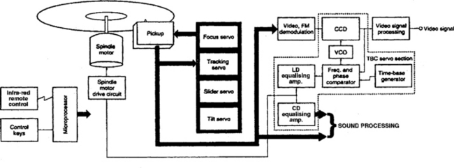
In normal operation the light beam is at precisely 90° to the disc surface. If the disc is warped the beam strikes it at some other angle, making for poor readout and consequent crosstalk from an adjacent pit-track. To prevent this a tilt servo can be incorporated to continually adjust the beam angle within the range ±2° and thus maintain its perpendicularity to the disc face. The pick-up assembly incorporates a tilt sensor in which a pair of photodiodes receive reflected light ‘sidebeams’ from an LED. The difference in their currents indicates the degree of tilt present, and is made to drive a tilt motor to compensate. A block diagram of the servo systems of a Laserdisc player is given in Fig. 20.4.
SYSCON, FIELD AND CHAPTER INDEXING
Laservision players, like videorecorders, have a comprehensive syscon section governed by a microprocessor containing RAM and ROM. As in tape machines it governs motor running, interpretation of user commands, safety functions, go-to, search and other trick modes. There are, however, several differences between videorecorder and Laserdisc syscons; the most fundamental being that the disc-syscon receives commands and feedback from the disc programme itself. These are in the form of digital codes, very similar to Teletext signals, inserted in some of the TV lines during the field blanking interval. The lines used are 17, 18, 280 and 281, and their signals (extracted from the replay signal circuits and decoded) have the following functions:
1. Lead in: the first 1000 or so tracks contain code 88FFFF to send the slide at 9× speed to the programme start point
2. Lead-out: the last 600 or more tracks contain code 80EEEE to return the slide to the beginning at 75× speed; during this time the signal circuits are muted.
The codes used during the programme itself depend on disc type. For CAV discs:
3. Picture code: a unique number for each individual picture in a programme, running from 1 upwards; about 45 000 individually addressable pictures is the capacity of a CAV disc. The picture number can be displayed in one corner of the TV screen if required, and memorised for subsequent quick access
4. Chapter code: a chapter number which identifies each segment of a programme; used for chapter search functions. Again the chapter number can be displayed on the TV screen at will. For CLV discs the range of functions is more limited, and the control data here is:
5. Code 87FFFF, corresponding to ‘normal play’ in which the special operation modes described above are disabled; and
6. Time code: a running count similar to the tape counter in a videorecorder. It provides a readout of elapsed disc time in minutes and seconds and can be displayed on the screen at will; and used with a go-to function, whereby the required time point is programmed by the user into RAM in the control microprocessor for automatic finding
LASERDISC SIGNAL PROCESSING
The CVBS signal, in standard PAL form, is frequency modulated onto a carrier signal (see Fig. 20.5), such that peak white corresponds to 7.9 MHz, black level to 7.1 MHz and sync tip to 6.76 MHz.

Fig. 20.5 Signal spectra for NTSC and PAL laserdiscs, without (early) and with digital sound recordings
Very little bandwidth-limiting is applied to the signal, so that its lower sideband extends down to below 2 MHz, and a replay response approaching 5 MHz is possible; the major area in the sideband for chroma signals is centred on about 2.5 MHz. On early discs audio-left and -right signals are frequency-modulated onto carriers at 683 kHz and 1066 kHz respectively, each with a maximum deviation of ±100 kHz. The amplitude of the sound carriers is about 25 dB down on that of the vision carrier. Later discs do not have this form of analogue sound track: their audio signals are recorded in digital form using the same EFM coded data as audio CDs. Fig. 20.5 shows that NTSC discs can carry both analogue and digital sound signals (a), while PAL types can carry one or the other but not both. In practice, late player designs have no provision for f.m. sound.
In the record system the signals may be represented as in Fig. 20.6, where waveform 1 corresponds to the frequency-modulated vision carrier based on 7.1 MHz, and waveform 2 the sound carrier. Adding the two renders waveform 3, which is now clipped or amplitude limited at fixed points equidistant from the zero line. The result is a PWM (Pulse Width Modulated) signal whose positive period determines the spacing between disc-pits, and whose negative period determines the length of each pit. This and the pit configuration are depicted in line 4 of Fig. 20.6.

During replay, the PWM signal from the disc surface appears as intensity-modulation of the spot of reflected light on the quad-formation pick-up photodiode array of Fig. 20.3. The outputs of all four diodes are summed to form the h.f. signal output, which is processed to recover CVBS vision, digital sound data, and (where applicable) separate L and R sound signals.
The complexity and high precision of the servo circuits and optical components, and the great bandwidth of the system considerably simplify the signal circuits compared to those of a videorecorder; in fact the only complication in the disc player is a need for phase-correction of the chroma signal in track-hopping modes with CAV discs. At each outward-hop (cue mode) the phase of the subcarrier jumps forward by 90° per track, and at each inward-hop the phase of the subcarrier jumps backward by 90°. To maintain correct burst phase sequence (Bruch blanking) in the field blanking period, and to thus avoid upsetting the subcarrier regenerator in the monitor TV, these phase errors are corrected by a phase-shifter in the chroma processing section of the player.
Replay processing
The carrier signal is preamplified and a.g.c.-controlled, then split off in several directions. One path feeds the servo circuits (see Fig. 20.4) and a second the sound circuits. Each sound carrier frequency is selected by a bandpass filter 100 kHz wide then amplified, limited and f.m.-demodulated to baseband after which de-emphasis takes place. The EFM digital audio signal is processed by circuits virtually identical to those in an audio CD player.
The vision signal process starts with an h.f. compensation stage, which is mainly concerned with equalising the h.f. signal throughout the playing time of a CAV disc, whose inner tracks are more densely packed with pits than the outer ones, leading to an initial shortfall in replay h.f. response. The ‘lift’ given to high frequencies is governed by the mean level of colour burst gated out of the demodulated CVBS signal. This process is called Motional Transfer Function (MTF).
Next comes a limiter to prepare the f.m. signal for demodulation. In fact there are two demodulators; the secondary one is fed by a 64 µs delay line so that it is working on a ‘1-line old’ signal. Incoming f.m. carrier level is monitored by a dropout detector which, when dropout is detected, throws the switch to select a good signal from the previous TV line, in just the same way as was described for videorecorders in Chapter 14. Because a conventional glass delay line does not have sufficient bandwidth to handle the full spectrum of f.m. signal there is a risk of spurious colour effects during the patch-job, and since no-colour is more acceptable than wrong-colour, a fast-acting colour killer is switched into the chroma channel for the duration of the dropout.
At the demodulator output the video signal splits three ways: to the luminance amplifier/process block; to the frame/chapter code detector (a simplified version of the text decoder described in Chapter 8); and via a 4.43 MHz bandpass filter to the chroma processing stage. The luminance signal passes through the timebase corrector (in CCD or digital fieldstore form) on its way to an edge-enhancer and then to an adder block wherein it is reunited with the chroma signal, which has now undergone the phase-correction process necessary to restore proper PAL order to trick-replay signals.
The third signal to the video adder block is the output of a character generator controlled by the off-disc track-code signals; this inserts the digits (corresponding to the picture number, chapter code or time-counter) in the output video waveform. Its output is enabled by a user ‘display data’ command. Data also passes, via a parallel data bus, from the decoder to the syscon microprocessor, conveying the essential control information for transport management.
Multi-purpose and multistandard disc players
Many Laserdisc players are designed for use not only with full-size Laservision discs but also with smaller ones using the same system, often including NTSC types. The output from the latter may be presented in ‘pure’ NTSC; NTSC-4.43; ‘quasi’- or true-PAL, depending on the design of the player and whether it incorporates a complete digital field store. All LDV players offer composite video output; some go further with S-video and/or RGB output ports. Also provided is a facility for playing standard audio CDs, in which every part of the machine, save the video processors, is used.
DVD PLAYERS
A relatively recent development, in terms of video disc evolution, is DVD (Digital Video Disc). While this system incorporates servomechanisms and laser-reading techniques similar to those in audio CD and LDV players, the rest of its design, in terms of both hardware and software, owes more to computer techniques than to conventional tape and disc programme-storage systems.
A DVD disc is the same size as an audio CD: 12 cm diameter and 1.2 mm thick. In both cases the programme data is stored in the form of a spiral of microscopic pits in the surface of the disc and is read off by a laser beam. The DVD, however, can carry a great deal more data than a conventional CD, primarily because the pits are smaller and closer together. The pit length for a DVD is 0.4 micron, and the track pitch 0.74 micron. To permit these tiny pits to be reliably read, the scanning light is a red laser whose light wavelength is shorter at 640 nm than the 780 nm of CD and LD types, see Fig. 20.7. The result is that the disc can store 4.7 Gbytes of information, which is roughly seven times the capacity of a CD, and can thus offer a playing time – using a MPEG-2 data-compression system of the sort described in Chapter 12 – of over two hours of high-quality (horizontal resolution greater than 500 lines) pictures, plus multi-channel digital surround sound. Also available are facilities for eight language channels and up to 32 subtitling tracks.
Disc capacity
A standard DVD disc is single sided like a CD or LDV. but because it is made from two 0.6 mm discs bonded back to back the format specification provides for a double-sided system (flip-over disc or double-side-play machine) and for a dual-layer disc, in which the two substrates of which the disc is made are both stamped with pit spirals, selected during play by moving the objective lens as necessary to focus on the required layer: Fig. 20.8 shows the principle. Combining the double-side and dual-layer techniques offers a ‘X4’ play facility on a single disc, with a capacity of 17 Gbyte/8 hours’ picture/sound replay.
Regional coding and encryption
Because the DVD format has no constrictions in regard to scanning standards or colour-encoding systems the software copyright holders (mainly film/movie companies) have made it a condition of their participation that discs and players are regionally coded. This ensures that software release around the world is controlled by them in a sequence which maximises profits from viewers and cinema-goers. The regions are shown in Table 20.2, and a disc released in one region will not work in a player bought in another region: a ‘flag’ is encoded onto the disc which prevents replay unless the firmware in the player recognises and permits it.
Table 20.2
World regions for DVD copyright coding
| Region 1: | The USA and Canada. |
| Region 2: | Europe, Japan and South Africa. |
| Region 3: | Asia. |
| Region 4: | Australia, New Zealand, Mexico and South America. |
| Region 5: | Africa. |
| Region 6: | China. |
Copy protection, too, is important to film companies who produce what amounts to digital master copies of films at retail prices, with playing rights confined to the household of the individual buyer: it must be made impossible to copy them onto tape or disc. This is achieved by a DES (Disc Encryption System) whereby the bitstream, containing interleaved video, audio and control data, is encrypted according to a secure 40-bit ‘random-key’ code. When the disc is played it is interrogated for an anti-copy flag – not all discs will carry this – and the player uses a key to decode the data. Copying is prevented by disruption of the colour subcarrier in the (e.g. PAL) analogue encoder or by blanking of the RGB output signals.
DVD signal processing
Fig. 20.9 outlines the stages involved in the DVD record and replay systems. The incoming video and audio signals are A-D converted, compressed and protected against data corruption and dropout. The vision signal compression system uses a variable-redundancy technique, depending on the programme material itself and the degree of quality required by the programme producer and the viewer – it varies from 1 to 10 Mbit/s, with a typical average of 4.5 Mbit/s. Electronically generated menus, subtitles and control data are added to make up a composite bitstream which then undergoes encryption according to the 40-bit key mentioned above. Further error protection is given to the data in the form of Reed-Solomon coding before modulation into an 8–16 form which governs the length of the pits impressed into the master disc from which the stamping die will be made. The disc speed varies throughout record and replay to give a scanning rate of 4 metres/sec in CLV mode.
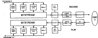
In replay the data pulses coming from the photodiodes in the reading laser assembly are demodulated and the tracking/focus feedback signals extracted from them. The following processes reciprocate those carried out on the signal during the conversion and recording stages.
DVD features
The vision signal carried on DVD can have 4:3 aspect ratio, but is usually 16:9; some discs carry 16:9 on one side and a 4:3 ‘pan and scan’ version of the same film on the reverse side. It is possible to produce a DVD disc with many hours’ running time at lower picture quality, acceptable for some types of programmes.
With-picture sound is encoded to MPEG-2 audio standard for Europe and to Dolby Digital (also known as AC-3) for the USA. Both sound systems are 5.1-channel ‘multi’ types, with a total of 6 audio streams: left front, right front, centre front (primarily for dialogue), left surround/rear, right surround/rear, and subwoofer (‘super-bass’). Unlike the matrixed surround system described in the next chapter, each of these has its own dedicated slot in the datastream to ensure good bandwidth and S/N ratio for each audio channel: the result is sharply ‘focused’ sound and a much closer approach to cinema sound reproduction. Up to eight different languages can be selected from one disc. There is also an audio-only format for DVD (PCM audio) which is capable of 16-, 20- or 24-bit sound with 48 kHz or 96 kHz sampling for performance beyond that of audio CD – for those with equipment and ears capable of appreciating it!
A DVD disc can offer up to 32 subtitle tracks in different languages, and their selection for display is independent of the audio language. This is beneficial to viewers with hearing difficulties.
Also within the DVD specifications is a disc format for the storage of computer data (DVD-ROM, with a complex copy-protection system) also the operation of interactive games and multi-media material. The DVD system makes provision for the use of a home-recording system with DV-R (3.9 G capacity) and DV-RAM (2.6 G), when disc recording will become a serious rival to tape systems for home use.
Player features
DVD players have an ability to play audio CDs by means of an optical lens with dual-focus capability. Parental control of viewing and features like aspect-ratio conversion are possible with a suitably encoded disc, along with ‘chapter search’ using off-disc data codes. Certain players offer additional features like picture zoom, optical audio-out ports and dynamic sound range compression, depending on model and price.