
VIDEORECORDER DECK CONTROL
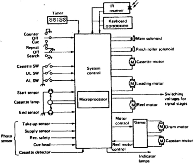
Modern videorecorders require a comprehensive deck control system to act as a ‘clearing house’ for user instructions and feedback information from deck status sensors, and to ensure correct sequencing of deck functions. It must protect the tape and deck mechanism from damage, prevent the user invoking conflicting or damaging commands, and present (in most machines) a front panel or on-screen display of the function in progress, the presence of the tape cassette and a warning of any malfunction or danger situation. An overall block diagram of the syscon (systems control) section of a videorecorder is given in Fig. 16.1. As can be seen there is a multiplicity of inputs and outputs, now to be dealt with in turn.
SYSCON INPUTS
The primary input lines to system control come from the user’s keyboard, be it on the front panel or on a remote handset. The main key functions, and the resulting actions of the syscon are as follows:
1. Play: Check cassette LED operation and end sensor signals. Unbrake reels, start capstan and head motors, initiate threading procedure; stop threading motor at threading end, unblank video and audio replay channels when servos locked; monitor deck functions thereafter
2. Record: As above, but first check for presence of cassette record-safety tab; switch on erase oscillator, switch sound and vision signal circuits to record; route head flip-flop squarewave to control-track head; switch servos to record mode; lock channel selector
3. Pause: Stop tape motion by braking capstan motor or withdrawing pinch roller; override deck rotation-sensor outputs to prevent stop mode being entered; start pause-time clock to prevent tape damage by entering ‘stop’ after a 5 minute period. In play-pause: shunt tape to correct point for noise-bar elimination and invoke artificial field sync pulse generator; in record-pause (some models) rewind tape 20–25 frames and prime edit-start circuit (see later)
4. Cue: Speed forward motion of tape via capstan or reel drive motor; speed up head drum to maintain correct fh; switch to ‘trick’ video heads where applicable; disable vision and sound blanking circuits
5. Review: Reverse and increase speed of capstan and/or reel drive motors; slow down head drum to maintain correct fh; switch to ‘trick’ video heads where applicable; disable blanking circuits; switch servos as necessary
6. Fast forward: Stop, unthread tape (some models), unbrake reels, turn take-up reel to fast clockwise, monitor end-sensor and any auto-cue system based on control-track markers i.e. QPF, APS; monitor counter-memory sensor and enter ‘stop’ when counter memory reaches 0000 or end-sensor fired
7. Fast rewind: As above, but turn supply reel anticlockwise and monitor tape start-sensor
8. Stop: Withdraw pinch roller, unthread, switch off capstan and head motors, brake reels, release lock on cassette cradle, switch vision and sound circuits to E-E mode
9. Eject: Check for and if necessary initiate stop mode; switch on cassette transport motor; extinguish ‘tape-in’ indicator
10. Audio dub: As ‘play’ but switch sound circuits to record and inhibit passage of bias oscillator signal to full-erase head
In addition to these command inputs, various feedback and guard sensors on the deck form a second important group of syscon inputs. These are:
1. Cassette-in detector: An optical or mechanical sensor activated by the plastic cassette shell. With no cassette present all deck functions are inhibited
2. Record tab sensor: A ‘feeler’ to detect the presence or absence of the removable erase-prevention tab on the cassette shell. With no tab, record mode is inhibited
3. Drum rotation sensor: Head PG or flip-flop waveform is monitored to assure continued rotation of the head; its absence will invoke stop mode
4. Spool rotation sensors: As above, but derived from Hall-effect magnet or optocoupler on spool turntable. To prevent tape damage, syscon enters stop when alternating sensor signal ceases
5. Tape start- and end-sensors: At each front corner of the cassette is mounted a sensor which detects the presence of the leader tape at the extreme ends of the ribbon; a lamp shining through the clear leader tape is used. When tape start is detected, any rewinding function is disabled; at tape end, only rewind commands will be accepted. Many machines have an auto-rewind feature, in which stop then rewind modes are consecutively entered by the syscon on receipt of ‘tape-end’ signal
6. Slack sensor: If at any point the tape becomes slack, the machine has malfunctioned and the tape could get damaged. Tape slack is detected by cessation of take-up reel rotation pulses
7. Dew detector: A resistive humidity detector fitted to the head-drum assembly inhibits all deck functions via the syscon if moisture has gathered. This prevents tape, drum and motor damage from the ribbon sticking to the drum surface. Very often a dew warning is provided on the front panel of the machine, and in some designs a head-heating element is switched on to dry the drum
8. Loading start/end sensors: All videocassette recorders have electrically driven tape loading/threading mechanisms. Until load-end is reached the loading motor must remain on, and many other mechanical functions inhibited; similarly, the tape must be fully unthreaded before head, capstan and loading motors can be switched off and the cassette released from the machine
9. Loading motor lock: If the loading motor stalls during load or unload the machine switches off altogether; this is particularly relevant to battery-operated portable videorecorders and camcorders.
In most videorecorders and in portable types, some of these deck status signals are given by a mode switch, a multi-contact slider or rotary type mechanically linked to the mechanics of the reel drive and tape-loading mechanism.
A further set of commands come to the syscon from areas other than the keyboard and deck sensors, as follows:
1. Timer command: At times preset and programmed by the user the deck is given ‘record’ and ‘stop’ signals from the timer section, which itself will select the programme-channel chosen by the absentee user. Some types of videorecorder use a single microprocessor, custom-designed and internally programmed for syscon, timer clock and display-drive functions
2. Power interrupt: If a power failure occurs during record or playback all motion ceases instantly; on restoration of power the machine will unload and stop. Some designs permit resumption of timed (pre-programmed) recording after a power cut. If the power switch is turned off during any ‘moving’ function the machine will unload and enter stop before turning off
3. Low battery: In portable equipment the battery voltage is monitored and at about 88% of normal voltage the unit enters stop and turns off completely to prevent over-discharge damage. The approach of this situation is often warned of by a flashing light on the control panel or in the viewfinder
4. Counter memory: a stop command passes into the syscon when the tape counter passes 0000 with the memory button depressed. In more sophisticated designs a ‘counter go-to’ number can be programmed into the keyboard, whereupon the syscon will drive the tape in either direction to the required count point
5. Remote control: A full remote control system duplicates the control panel functions, and will be dealt with below and in Chapter 22. Particularly relevant to portable equipment is the camera trigger which operates the record-pause function described early in this chapter.
SYSCON OUTPUTS
The syscon has access to all the mechanical movers on the deck, and switches command lines to various electronic sections. Not all of the below-listed outputs will necessarily be provided, depending on the vintage, price and degree of sophistication of the machine.
1. Motor controls: start, stop and three speed conditions for the drum motor; for the capstan motor, stop, run and where applicable run forwards and backwards at various speeds – half speed for LP operation; run, stop, reverse for the loading motor; run, stop, reverse for any cassette loading motor; run, stop, reverse and speed control for reel motor(s) where fitted
2. Solenoid controls: since all mechanical operations of the deck must be carried out electromechanically, solenoids may be provided for the following purposes: pressure-roller application; fast-forward/rewind lever; play lever; loading-drive engagement where no dedicated loading motor is employed; and reel brake application
3. Indication lamps: front-panel or viewfinder indications of machine function and status, they can range from simple LED point-emitters to dot-matrix pattern displays in fluorescent or LED display panel matrices, or electronically generated symbols or characters on the viewfinder or TV screen
4. Signal switching: output lines are provided to switch on and off sections of the machine as appropriate to the mode in use. These may typically be REC + 9 V, PLAY + 9 V. AUDIO DUB + 9 V, REC/PLAY + 9 V, MUTE HIGH, CH LOCK. The latter inhibits channel change during record so that servo instability is prevented; CH LOCK signal disappears during rec. pause mode.
CENTRAL PROCESSOR
The heart of the syscon is invariably a microprocessor. A 4-bit type is most usual, with on-board ROM containing an instruction set appropriate to the videorecorder design and deck members. Very often this ROM is permanently programmed by or at the request of the equipment manufacturer to suit his design, the rest of the micro being of a standardised type; this ROM programme is defined by the suffix of the type number, very important when the device is replaced in a repair situation. Increasingly, microprocessors are being custom-designed for specific videorecorder or camcorder applications, particularly where the equipment manufacturer is also in the business of designing and producing ICs. This approach greatly simplifies the interfacing circuits between the syscon and its peripheral devices such as keyboards, remote control systems, motors and solenoids. It also permits the use of a single micro for all ‘intelligent’ operations within a budget-priced machine, in which timer, clock, display drive, servo and tape counter operations may be dealt with inside the same package as the syscon process itself, reducing cost, complexity, interconnection links and component count.
A small RAM capacity is also provided on board the μP chip to store user instructions and deck status data pending decisions or execution. Unlike conventional computing systems where memories, interfaces and codes are separate from the CPU, the one-chip microcomputer used here contains parallel processing CPU, ROM, RAM, I/O ports, programmable timer, control circuit and clock oscillator, see Fig. 16.2. Typical ROM and RAM capacities in a syscon microchip are 3000 × 8 bits and 96 × 8 bits respectively. No great speed in operation is required, especially as the micro spends virtually all its time waiting instructions – a clock oscillator rate of 400 kHz is typical, with an instruction cycle of 10 μs.
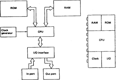
Fig. 16.2 Internal architecture of typical mask-programmed 4-bit microcomputer as used for videorecorder syscon applications
A block diagram of a typical syscon circuit, also incorporating the servo section, is shown in Fig. 16.3. There is little point in attempting to indicate the internal blocks of the microprocessor section; these devices have to be regarded as ‘black boxes’, and their internal workings are inaccessible anyway. Leaving out the servo section, dealt with in the last chapter, we start at the bottom left-hand corner with chip pins 115/6/7. Normally held high by the adjacent pull-up resistors, these three lines are selectively and sequentially grounded by the wiper contacts of the deck-mounted mode switch to indicate to the syscon the state of the deck mechanics. In this particular design the deck mechanics (see Chapter 18) are driven by a loading motor, here commanded – via a drive IC – by syscon chip pins 11 and 12.
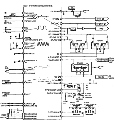
The other functions which concern us here are operated by the pins in the lower right-hand side of the diagram. IC pin 20 is held low when the safety tab switch S6001 is closed in the presence of a pre-recorded cassette whose tab has been knocked out: this inhibits record mode. IC pin 108 pulses the tape-end sensor LED D6001 which is mounted at the front centre of the cassette shell; when the tape is fully rewound its light falls on phototransistor Q6002, pulsing down IC pin 94 to inhibit rewind when in stop mode or to invoke stop mode at the end of tape rewinding. Similarly the supply phototransistor Q6003, mounted on the left side of the cassette cradle, sees pulsed IR light from D6001 when the tape is fully wound on to the take-up spool (tape end condition) and signals the fact to IC pin 95 by pulsing it low. Now all forward modes are inhibited and stop or auto-rewind mode entered. When the tape is at an intermediate position the photosensor transistors are high impedance, the pull-up resistors hold chip pins 94 and 95 high, and any function is permitted.
The reel sensors here are optocoupled types, with the light from the emitter LED in each of IC 6002/6003 being alternately passed to, and blocked from, its phototransistor by castellations on the spool turntable, several times per revolution. The squarewaves thus generated pass into the IC on pins 70 and 71, where they are used not only for deck ‘emergency’ monitoring as described earlier, but to decelerate the tape as it approaches rewind-end; and to calculate and display tape time elapsed or remaining. This function is separate from the real-time counter, operated by the CTL pulses at chip pins 82/83.
As the pin-count of this IC suggests (it’s a 124-lead flatpack) it has many functions in addition to those shown here. We shall meet some more of them in Chapter 22.
SYSCON INPUT MATRICES
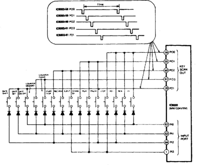
The large number of operating keys associated with modern videorecorders and camcorders necessitates some form of matrixing system to reduce the number of input pins required on the microprocessor. Two approaches are possible, key-scan and A–D conversion. The key-scan method is illustrated in Fig. 16.4, which is taken from a Panasonic camcorder. Here IC6003 pulses its key scan ports P00, P01, P02, P03 and P21 at 11 ms intervals, each port having a different pulse timing. When an operation key is pressed one of these scan pulses is fed back into one of the input ports P10–P13 of the same microprocessor IC6003. The micro’s programme now compares output and input pulse timing to detect which button was pressed, and implements its ROM-based operation accordingly. Note the date manipulation keys at left of Fig. 16.4: these commands are routed to an electronic character generator. Five pulse phases and four input ports give a possible total of twenty key combinations, of which fifteen are used here, with only nine lines in the keyboard link. Even greater is the economy of link lines in the A–D converter system.
An outline of the principle of a control system using A–D conversion is given in Fig. 16.5. The operation depends on a 4-bit data bus D0-D3 which presents a μP-generated running count of 0–15 in binary terms as shown by the lower waveforms of Fig. 16.5(b). This is applied to a D–A converter consisting of an R/2R network (top of Fig. 16.5(a)) to generate the staircase waveform shown at the top of Fig. 16.5(b): it has sixteen levels ranging from near-zero to near-supply voltage, which might typically be 5 V. This continuous staircase is applied to one input of an op-amp comparator as ‘V+’. Now consider the bottom section of Fig. 16.5(a). Here is a ladder network of resistors with each operation key arranged to ground a section of it. The result is a high voltage at the right-hand side of R7 with no key pressed; and some lower (but closely specified) voltage for each key – ‘play’ may give rise to a voltage of 4.63 V, ‘stop’ 4.25 V and so on, according to the nature of the precision resistor chain R7-R20. This specific ‘function voltage’ is presented to the inverting input of the op-amp comparator.
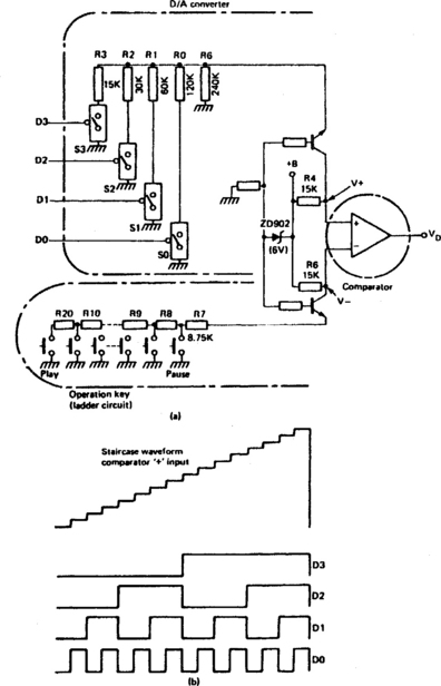
Fig. 16.5 A–D conversion system for operating-key identification: only two conductors link the key-pad to the rest of the circuit. (a) Basic circuit; (b) waveforms on data line and internal D–A conversion
When any function key is pressed the inverting input of the op-amp moves negatively; output (VD) will rise as soon as the staircase waveform at its + input permits. This signals to the micro that a command has been keyed in. Acting on this, the micro now resets the data lines D0–D3 to 0000 (VD reverts to low) then increments from 0001 upwards to raise the staircase signal, applied as V+, one step at a time. At some point in the sixteen-step count the V+ input to the op-amp will exceed that of the V– input, whereupon VD will go high once more. The running count is now frozen and examined within the micro. For example, the count may be 1001 which ROM will say corresponds to ‘rewind’. This will then be implemented by the microprocessor, subject to the constraints of deck status sensors. By means of this A–D conversion process, up to fifteen keys can be accommodated by five microprocessor ports, D0–D3 plus switch-data input. The actual keyboard depends on only two connections (V– and ground) provided it incorporates the ladder resistor; this paved the way to providing a full-function corded remote control system using only one pair of conductors in the link-wire – the ladder resistor is duplicated in the remote handset.
MICRO PORT EXPANSION
The two methods of input-key matrixing described above represent one form of port expansion. In many cases the computing power required (small in relation to that of home computers and calculators) can easily be provided within the compass of one IC package. Difficulties arise, however, with the sheer number of pins required on the package, and particularly with the physical arrangement of printed conductors on the chip’s mounting panel. Between 80 and 160 pins is the norm for a microprocessor.
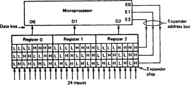
Expander systems are used to route information to and from a micro on a time-sequential (strobing) basis under the control of expander-address bus data generated by the micro. Fig. 16.6 gives an idea of how this system works. There are three expander address inputs to a port expander chip: E0, E1 and E2. Three binary input lines give eight possible combinations from 000 to 111, and these eight addresses in the expander chip are accessed on a continually rotating basis. Each address corresponds to one input (usually a ‘latched’ port which holds one signal until it is replaced by another). The input is routed through a switch to one input port of the micro each time its address comes up. The pre-programmed micro thus polls each of the eight input points in turn, recognising them by the address-code being generated at that time. In the particular case of Fig. 16.6 three micro ports can thus monitor 24 inputs via six connecting leads – three in the address bus and three in the data bus. For the sort of status, command and feedback information used in electromechanical control of videotape and videodisc decks and peripherals, the relative slowness and discontinuity of this form of data transfer is not important. The same port-expander principle can be and is applied to microprocessor outputs too, whereby the micro holds the output data intended for each specific output point until its destination address is generated, when it is released onto the data bus. It is also possible (following standard computer practice) to utilise a bi-directional data bus system with programmable I/O ports, but this degree of complexity is seldom necessary in domestic entertainment systems. An example of a bi-directional data bus is given in Chapter 22.
Other artifices to reduce the interconnection- and IC pin-count are used as alternatives to strobe port-expansion. Some processors – typically custom-designed types for miniature equipment – use ternary (tri-state) logic in and which three levels (high, medium, low) of voltage are used and recognised. Another approach is the use of serial data, which generally requires the use of shift-registers as clocked parallel-to-serial and serial-to-parallel converters at sending and receiving ends respectively.
CLEAN-EDIT FUNCTIONS
In a basic videorecorder, invoking the pause function will merely stop the tape transport. When the pause key is released once more it is not possible for the tape to instantaneously attain normal speed, so that in effect, video tracks and (where applicable) control tracks on the tape become ‘bunched up’ at the pause point. The result is particularly noticeable on record pause because during subsequent replay severe picture and sound disturbance results from the mistracking and momentary servo instability at the point where the tracks are disordered. At best, a second or so of programme is lost while the blanking system waits for a new servo lock.
To prevent these effects home-base videorecorders have a syscon equipped for clean assemble edit. This normally takes the form of a ‘back-space’ system, as illustrated in Fig. 16.7. The upper shaded section of the diagram represents the tape travelling towards the right in record mode. At point (A) the pause key (start-stop key on camera) is pressed, whereupon the tape rewinds for about 1–1.6 seconds then comes to rest in the record-pause state (B). It is still laced up. When the next recording segment is ready (scene changed for camera, commercial break finished, or alternative video source selected from tuner or auxiliary video player) the pause key is once again pressed (C). Tape transport restarts immediately but the syscon does not yet switch the electronics to record. A ‘play’ period (D) of up to one second is permitted, during which time the capstan runs up to normal speed and its servo attains lock. At this time the capstan servo is directed by the syscon to lock incoming vertical syncs to existing replayed control track pulses in readiness for the changeover from old to new programme material.

A few frames (tracks) before the end of the old recording a changeover to record mode (E) is made in signal circuits, servos and control-track pulse routeing, and this is arranged to take place during a field blanking period. The result is a completely smooth changeover from old to new material, with regard to both video tracks and control pulses. The presence of old and new tracks simultaneously on tape momentarily can give rise to crosstalk, especially where the old scene is highly coloured or contrasted and the new one lower-key. For the short period of over-recording the luminance writing current is increased by about 2 dB in order to provide a more effective erasing action – the full-width erase head is too far removed from the drum to take any part during this period. The resulting edit is very effective, though under some circumstances a burst of spurious colour appears momentarily at the edit point – at low colour-under frequencies the recording-erase process is less effective. Some domestic machines incorporate separate flying erase heads on the drum itself for use during in-camera assemble edits.
Although the backspace record-pause cycle takes less than two seconds in total, the number and speed of output manipulations by the syscon at this time are many and high. In a typical machine the following parts are accessed and instructed at least once: loading motor, mode switch, reel brakes, capstan motor, servo circuits, recording f.m. amplifier, video signal routeing, user indications and (where applicable) flying-erase head switching.
Insert edit
The process just described will give continuity of replay servo synchronisation in circumstances of assemble edit, where each new sequence follows on from the previously recorded material, i.e. when the camera stop/start trigger is used to select each ‘live’ sequence in turn; or in a post-production situation where a master recording is being assembled from one or more 1st-generation tapes.
Where it is required to modify an existing recording by inserting new material, the method is not effective at the end of the inserted section because video and control tracks will be disordered at the point of reversion to the original material. The insert-edit system is designed to overcome this problem. Here only the video and audio tracks are erased during the insert recording, leaving the original control track to ‘master’ the head-drum phase and capstan speed. The continuity of the control track ensures a disturbance-free transition at each end of the inserted section.
In formats using tracking tones within the vision tracks, other methods are used to achieve edit control.
SYSCON MICRO INTERFACING
The syscon microprocessor is a wholly digital device and deals with all inputs and outputs in binary form. Since most commands and feedback indications appear as on-off signals there is no difficulty in matching them to the requirements of the chip – beyond the need for the port expansion, strobe or codec systems already described. Most syscon outputs, too, are easy to apply to their recipients; motor commands merely toggle electronic switches in motor drive amplifiers (MDAs) and signal-routeing is also carried out by ‘local’ electronic switches. The current-sourcing capability of a microprocessor port is not sufficient to drive any ‘end-user’ beyond a fluorescent display panel, however, so for indication-LEDs, relays and solenoids, buffer stages incorporating further ICs and/or transistors are used; they have the additional advantage of protecting the micro from electrical damage; providing ‘fan-out’ capability; and if required the facility for logic inversion. Relays and solenoids have special requirements where they may be held in for long periods – the required pull-in and hold-in currents are greatly different, and can be catered for by two separate windings: a heavy, high-current one is momentarily pulsed to pull-in, then a low ‘hold’ current is maintained through the other. In some custom-designed syscon micros, separate pull and hold output pins are provided. Alternatively an RC charging circuit provides the initial pull pulse. In very energy-conscious portable video systems latching relays and solenoids are used, in which a magnetic armature holds the selected position after a single ‘pull’ pulse in the right direction through the coil.
KEY PRIORITIES
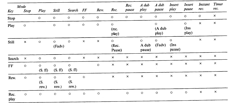
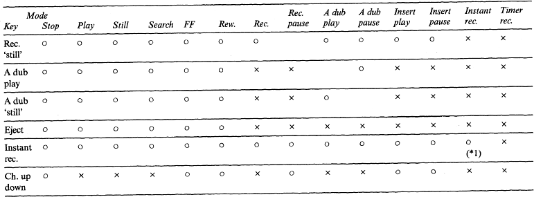
Another vital function of the syscon is to assign priorities and prevent conflicting functions being keyed. Timer systems are pre-programmed to reject impossible requests like ‘record for twelve hours’, ‘record two programmes at once’ or ‘stop recording before start time’; attempts to pre-programme a recording on a tabless cassette will result in eject function. Similarly, such mechanically destructive orders as ‘pause’ during rewind mode, and pointless commands like ‘search’ during record mode are rejected. In most machines, pressing two keys simultaneously will have no effect on the function (if any) in progress; obvious exceptions are record + play, audio dub + play and play + still. A typical mode shift table for a mains machine is given in Table 16.1.
SYSCON TROUBLESHOOTING
Microprocessors are inherently very reliable devices, as are their attendant expansion, bus-buffer and slave chips. Their internal workings are neither obvious nor important from the point of view of servicing work. The physical problems involved in removing and replacing a 80- or 160-pin chip are considerable, especially where double-sided PC boards and miniature high-density construction methods are used. Before condemning any syscon-associated chip it is important to establish that the peripheral devices are correctly coupled and fault-free.
Mechanical and physical problems are most often at the root of what may appear to be an obscure system-control fault. Mechanically operated switches are perhaps the most unreliable devices in the ensemble, and typically cause wrong indications in the feedback system: a machine which refuses to accept a cassette but whose motors are running will probably have a faulty unload-end (mode) switch; one which makes no response to its deck-function keyboard should be checked for a faulty cassette-down switch or cassette-lamp; one which unloads within seconds of loading completion may well have a load-end (mode) switch problem or a slipping loading belt. Wherever wear- and corrosion-prone links in the chain are suspect, they should be checked first – belts, switches, relays and solenoids are high on the list. Optocouplers and to a lesser extent Hall-effect rotation sensors are suspect where a persistent ‘shutdown’ situation arises; oscilloscope and meter checks of deck sensors’ outputs should quickly ascertain the cause. Do not forget the head-rotation sensor, based on its PG pulse generator.
Much can be eliminated by a close study of the symptoms and a knowledge of the syscon’s ground rules. A machine which continually goes into auto-rewind may have some leakage problem in its tape-end sensor; a situation where control keys operate wrong functions via an A–D converter circuit should lead to a check of the keys and keyboard for electrical leakage and then the A–D converter circuit and ladder resistor; one group of keys inoperative in a key-scanned machine suggests the loss of one strobe pulse; a refusal to accept a ‘record’ command can often be quickly traced to a faulty recorder-tab detector switch or the failure of its ‘OK’ message to reach the syscon centre; and so on. In all situations suspect the ICs last, and make the diagnostic process one of checking that all control and feedback information is correctly arriving at the input ports of the micro, and that all commands from its output ports are getting to their destinations, and there being correctly acted upon.
Complete lack of action and response in the micro will usually be due to failure of its operating voltage or cessation of the clock oscillator – which generally depends on an external ceramic filter or RC network tuned to around 400–600 kHz. Random functions at switch-on, ‘disobedience’ or no response may be due to a lack of reset pulse. Occasionally, interference spikes on the mains supply (or static charges around a portable) can ‘unhinge’ a micro, leading to random and bizarre functions; de-powering for a period to invoke a reset pulse usually clears the trouble. A similarly obscure set of symptoms can arise from one line in a data-, address- or control-bus becoming ‘stuck’ high or low – physical faults as well as faulty chips can cause this, and an oscilloscope and multimeter can be used to trace it. A logic probe is useful here; a logic analyser (see Chapter 22) is only required when it is necessary to check the timing and nature of the data on the bus, and that is quite rare.
AUTO-DIAGNOSIS
Many videorecorder designs make provision for ‘self-diagnosis’, in which a readout gives information on the cause of the last malfunction or shutdown, either automatically or when the service mode is called up by a technician. This is useful in routine diagnosis, and invaluable when the trouble is intermittent – the fault data is held in memory. An example of a self-test indication display (from the same Panasonic machine as the diagram of Fig. 16.3) is given now in Fig. 16.8. It is one of a whole series of stored error and malfunction indications which this machine provides for both the user (to report) and the technician: there are seven service modes in total, each addressing a different aspect of deck and control operation.
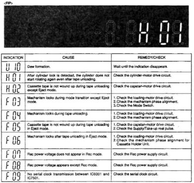
Fig. 16.8 Diagnostic readout in the flourescent front panel display of a Panasonic VCR. This one, H01, indicates that the head drum is stalled
The auto-diagnostic facilities provided vary between manufacturers. The vital thing is to ascertain that a self-diagnostic function is present and then to find out how to call it up and how to interpret the displayed data. All these are covered in the service manual for the model in question.