CONTROL SYSTEMS
The increasing sophistication of TV and video equipment (reflected in earlier chapters of this book) and its interactive nature has necessitated the development of control systems which are largely automatic in operation. They devolve into three broad groups: user-control of equipment function; equipment-internal management of data and commands; and inter-equipment links, in which the operation of associated units is co-ordinated by ‘command’ links between them.
The most tangible and familiar of these is the cordless remote control handset by which much modern consumer entertainment equipment is ‘driven’. The serial data link takes the form of an infra-red (IR) transmission, in which the carrier is a beam of light whose wavelength is about 950 nm (frequency 316 000 GHz), which lies just below the visible spectrum. This very high carrier frequency permits the use of advanced modulation systems: the data is invariably transmitted in serial PCM form with the IR carrier turned fully on or off in a closely defined time sequence. As with all PCM systems, it is the pulse timing and nothing else which defines the command, and the use of check codes and filters – electrical and optical – gives great immunity to interference and misinterpretation of commands.
Internal data management has already been touched upon in the syscon arrangements described in Chapter 16. Various serial and parallel data bus formats are used within single equipments, their complexity depending on the features offered. Internal data systems are required to interface with RC receiver/decoders, and generally require access to ROM and manipulation of RAM; this is particularly relevant to FS tuning systems (Chapter 3), teletext and viewdata (Chapter 8) and deck control for both videorecorders (Chapter 16) and disc players (Chapter 20). For the latter some very sophisticated control systems are used in conjunction with a computer in interactive video applications.
Systems are also available to control signal-routeing and operating conditions in separate, but inter-linked equipments, and can be implemented by remote handset or even over the telephone. One such system will be described towards the end of this chapter.
IR REMOTE SENDER
As can be seen from the circuit diagram of Fig. 22.1(a) the component count of a modern handset is very low, consisting here of twelve electrical components plus the battery and keyboard. The single IC is designed for minimal current consumption (<2 μA) in standby to conserve battery energy. The clock oscillator has no need of high precision or stability, and the cheap ceramic resonator connected between chip pins 11 and 12 provides an adequate frequency reference around 450 kHz. When no button is depressed the oscillator is off. Pin 1 of the chip is low, transistor TB01 off and the transmitting LEDs DB01 and DB02 off.

When a key is pressed a current is detected within the IC and the oscillator starts. To prevent false operation due to key-bounce a 20 ms period is allowed before the key-detect process starts, when IC output pins 13–19 are strobed via a key-scan system (refer to Fig. 16.4 and associated text). A return pulse enters the chip on one of pins 5–8 and is decoded to identify the function requested. Even if the key is released at this point, the entire command word is generated and transmitted before the circuit returns to standby; if two or more keys are pressed simultaneously the commands are rejected.
Each key retrieves a specific command code from chip-internal ROM, and the required bit-sequence is made up by a processing section within the chip, driven by the clock. Remote control commands are pulse-position coded, each pulse consisting of a burst of 38 kHz carrier – this permits the use of a sharply tuned filter at the receiver for immunity from noise and interference. The spacing between pulses determines whether the pulse represents 0 or 1: a 7.59 ms period indicates a 1 and a 5.06 ms period a 0. A complete command consists of eleven bits: a reference bit, a toggle bit, three address bits and six bits for the actual command, as shown in Fig. 22.1(b).
The first bit is always 1, and is for use as a time reference in the decoder – its duration is measured, stored and used as a time base for the serial-to-parallel decoding process of the pulse-train which follows. The second (toggle) bit changes state each time a key is pressed, so that the decoder can discriminate between ‘new command’ and ‘end of interruption in transmission’, e.g. someone walks through the light beam. The need for the toggle bit arises because the data transmission is continuous while any key remains pressed, in order to operate analogue functions like brightness and volume. On the other hand such functions as teletext page selection need sequential number keying, for which the toggle bit resets the decoder.
The next three bits are address bits which identify the sender and receiver/decoder, and act as a turnkey for the decoding of subsequent bits. In simple RC systems like this one a single address is used; here it is address 0, whose code (Fig. 22.1(b)) is 111. Finally comes the command itself in the form of a 6-bit code. Six bits offer 64 combinations, not all of which are used. The code 010001 is shown in the diagram, corresponding to ‘channel 6’ in this system: 001100 is brightness-up; 011110 will switch the set into standby, and so on. If any key is held down continuously, its command is repeated every 121 ms.
The pulse-coded output appears at pin 1 of the IC, and via RB02 switches output transistor TB01 between heavy conduction and cut-off. The sampling resistor RB01 and feedback transistor TB02 maintains peak LED current at around 1.3 A. The internal resistance of the small battery used is too great to supply this order of current, so large reservoir capacitor CB04 is essential. Because of the low duty-cycle of the pulse signal, however, the average battery current is only 14 mA during command transmission. Even at the rate of 1000 commands per day the battery life is many months. DB03 protects the IC from the effects of reversed connection of the battery. The circuit will operate over a wide range of battery voltage though imminent exhaustion is signalled by insensitivity.
MULTI-FUNCTION REMOTE CONTROLLER
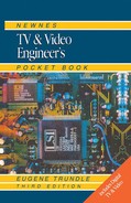
In the description above, mention was made of the address code, which forms the third section of the RC command word. By changing the address codes and programming receiving decoders accordingly, the three bits offer eight possible addresses, which means that eight different pieces of equipment can be operated by the same handset. A more sophisticated application of the same technology is embodied in a multi-function encoder/transmitter IC, which can handle up to 2048 separate commands, placed in 32 addressable groups of 64 commands each. The transmitter has a similar start/debounce cycle to that already described. Here the code is transmitted in bi-phase form, whereby a digital 1 is signalled by a rise in potential during one bit period, and a digital 0 by a fall in potential during one bit period. See Fig. 22.2. Each bit period is 1.78 ms, and as long as a key is depressed the data word is transmitted at intervals of 64 bit periods, 114 ms.
The bit structure for the transmitted code is shown in Fig. 22.2. The first two bit periods are occupied with debounce and key scanning. The transmission begins with two start bits to set the operating point in the receiver’s a.g.c. circuit, followed by a control bit (similar to the previously described toggle bit) to indicate a new transmission. There follow five system address bits S0–S4 which can be set by a selector switch on the handset or (for ‘dedicated commander’ applications) hard-wired in one of the 32 possible configurations. The command is conveyed by the next five bits C0–C5.
Because of the large number of possible slaves for this system, and to ensure standardisation between different manufacturers’ equipment using it, the address codes have been standardised by the IC maker as shown in Table 22.1. The command codes have also been-standardised so that the same (symbol marked) buttons on the handset are relevant to all equipment addressed. Thus ‘play’ command code 110101 will be recognised by videorecorder, disc player, audio cassette player etc. once correctly addressed, as will ‘volume up’ (010000) ‘go to standby’ 001100 etc., the latter two commands also being relevant to a TV set.

IR RECEIVER AND DECODER
The infra-red RC signals are detected by a photodiode whose standing current is modulated by the incoming light pulses. A sharply tuned LC filter immediately follows the diode to reject noise and out-of-band (38 kHz) components. Next comes a preamplifier whose main characteristic is its very wide a.g.c. range of about 140 dB, required to cope with the large variation of IR signal level which may be encountered.
In simple receivers the coded message is simply converted into parallel data and decoded to give a series of output lines, each of which change state when the corresponding button of the remote handset is pressed. Such outputs are used for channel selection; for off- or standby-switching via a solenoid on the mains switch or a ‘pull-down’ line to the PSU; and for control of such analogue functions as brightness, colour and volume, where the appropriate control line feeds an interface IC whose PWM output is varied in respect of duty-cycle for as long as the command is received, and held constant thereafter. Integration of this PWM pulse train in an RC circuit renders a d.c. control voltage for application to the voltage-controlled attenuators (VCAs) within the signal-processing chips described in earlier chapters, e.g. colour decoder.
ADVANCED REMOTE CONTROLLERS
Advances in technology and consumer demand have led to many ‘special’ types of remote control, primarily designed to make operation simpler for the user; to replace lost or faulty units; and to facilitate house-wide operation. They are described below.
Learning and ‘Universal’ types
Learning remote controls have both an IR receiver and an IR emitter at the front end. To ‘teach’ them the commands for any piece of equipment, the original handset is placed head to head with the new one, and the latter set to receive mode. Now the commands are passed into the new handset and stored in memory for reproduction in send mode. At the press of each key the code of the original is mimicked, and this type of remote control can learn and reproduce the codes for several different pieces of equipment: TV, VCR, satellite, audio etc
An alternative technology, especially useful where the original handset has been lost, is the Universal remote control. Stored in memory inside it are thousands of control-code groups for a huge range of TV/video/audio home-electronics products. For any given piece of equipment the required code can be called up (found by trial and error if necessary) and assigned for use. Again several different equipments can be controlled from the one handset using a selection key.
Extenders
Infra-red light beams cannot travel through walls or floors and when (as is often the case) there is an r.f. distribution system in the dwelling, the need arises to control it from one or more of the remote TV sets. An extender system has two components, a receiver and a relay, both mains powered. The receiver module is placed near the remote TV to pick up infra-red commands there and convert them to a radio transmission, typically at a low-UHF frequency of 418 MHz. That is picked up by the relay module, placed in sight of the equipment in the living room, to which it radiates reconstituted IR commands, mimicking those of the original handset: TV, video, audio and satellite equipment can thus be controlled. A variant of the system uses a clip-on (battery-powered) module at the front of the remote control handset to extend its range house-wide.
LCD-programming handsets
For use with VCRs, some handsets have an LCD display built in: its drive electronics are incorporated in an encoder IC of the type already described, along with a small data register or memory. For timer programming, all the required data of date, start/stop times, TV channel and recording speed are composed by the user in the LED display on the handset and written into the data register. When it is complete a ‘transmit’ prompt appears in the display and a stroke on the ‘send’ key conveys all the data in the register via the IR control link to a similar register in the VCR. Here it is decoded and briefly displayed – on the front panel readout – for confirmation, then stored as timer information to be actioned when stored time and real-time data matches.
A simpler programming system, also using an LCD handset, is the Video Plus concept by Gemstar. Here each TV programme has its own numerical code consisting of 3–7 digits, printed in newspapers and programme guides. Keying this number into the handset while in VideoPlus mode permits its assembly into a data register, and subsequent transmission to the VCR where (in conjunction with the real-time clock data) it is decoded into start/stop times and TV channel data for action when the programme is transmitted.
Another type of LCD handset is used in conjunction with sophisticated digital satellite-radio systems of the sort described on page 93. Alongside the normal IR transmission LED is a receiving IR photodiode, responsive to a data-transmitting LED on the satradio set’s front panel. Along with the audio data, information on the channel, track title, artist, composer, CD reference number etc. is broadcast, and this is transcoded to an IR datastream for passage back to the user’s handset and display in its LCD panel.
PDC programming
Timer-event programming by manual or VideoPlus means cannot properly capture a TV transmission which is rescheduled in time, or is delayed by (e.g.) a previous programme overrunning its time, as may happen to ‘live’ news or sport coverage. Neither of these systems have any link to the programme’s identity beyond its published date, time and transmission channel.
To overcome this problem, all broadcasters are party to the PDC (Programme Delivery Control) system, in which the recording action is triggered by data sent with the programme transmission itself: this can cater not only for late running, but for complete rescheduling of the wanted programme, on the expected channel, or on any other which the tuner can receive and is logged in its tuning memory.
PDC data is incorporated in the teletext signal, where it occupies packet 8/30, not displayed on the teletext screen. The transmission and decoding of teletext data was covered in Chapter 8, and applies equally to the PDC signal, though here the decoding circuit is much simpler, as the IC diagram of Fig. 22.3 shows. The broadcast video signal enters on pins 1 and 2 where text and sync pulses are gated out and passed to a data-acquisition stage whose address corresponds only to text packet 8/30, transmitted once per second on TV line 16. The data it contains is thus extracted and held within the IC’s register, looking for a coincidence between the user’s timing instructions (entering from the system-control section on the I2C lines SDA and SCL, details later) and the stored PDC data. When they correspond instructions for channel selection and record mode are output on the same data bus and so the recording commences, terminated later by off-air instruction at the end of the broadcast programme. Apart from the video input and the I2C bus line links on pins 8 and 9 the other connections to the chip are mainly concerned with ‘housekeeping’ functions: the RC network at pin 17 is a loop filter for the PLL; pin 12 provides a flag to indicate reception of PDC data; pins 14 and 11 provide test facilities; and the clamp reservoir capacitor at pin 5 stores the operating level for the adaptive sync separator.

Fig. 22.3 PDC control IC SAA4700. All control data enters and leaves the chip via the I2C bus at pins 8 and 9
User instructions come via the remote control keypad as time/date/channel or VideoPlus data; it is converted within the VCR to a ‘packet’ form suitable for PDC programming. In many late-model VCRs the system control IC incorporates the PDC dataline decoder.
AUTO-TUNING AND CLOCK-SET
Because text packet 8/30 contains all the data on station identification, broadcaster, real time etc. it facilitates an auto set-up system in which a TV or VCR can be automatically tuned and have its clock accurately set. The auto set-up programme is initiated by the user during installation, whereupon the syscon section sweeps the tuner through all the broadcast bands for which it is equipped, stopping briefly at each transmission it encounters for download of broadcast frequency, signal strength and PDC data. When the sweep is complete all the data is analysed and sorted so that the strongest and cleanest available carriers are used, and assigned to tuning memory as 13-bit references, in order (for the UK) BBC1, BBC2, ITV, CH4, CH5 etc. so that the user’s channel selector keys call them up in that sequence. Time of day (and date, if required) is extracted from the text data and used to set the front-panel or on-screen clock, greatly simplifying installation for an unskilled viewer.
MICROPROCESSOR CONTROL
Chapter 16 described the mechanical control of a videorecorder deck by a microprocessor system. The control processor of a VCR has many functions beyond the deck, however, including those described already in this chapter. For tuning, mode control, system selection and signal-source selection it has much in common with the TV control system to be described now. It is based on the use of a microprocessor and an EEPROM (non-volatile) memory chip.
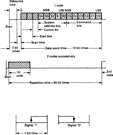
Figure 22.4 outlines a typical TV control system, largely applicable to VCRs too. The central processor is an 8-bit type deriving its clock pulses from crystal XL1. It has a mask-programmed ROM (16 kbyte) section containing its mode and operating instructions, customised for the make and model of receiver; and a small RAM (512 byte) for temporary storage of user instructions and other data.
At power-up the processor is reset, and then feeds stored factory set-up data along the I2C bus to all the peripheral ICs on it; these are ‘default’ settings which establish the initial values for brightness, volume, colour level etc. At the on command from the remote control the PSU section is switched on and the required broadcast channel data fetched from EEPROM memory, converted to an analogue level and fed to the tuner. The OSD section has a decoder/character generator which injects RGB signals into the video amplifiers. The text, symbols and graphics for these are generated within the control processor; we have seen in Chapter 8 how a complete teletext decoder can be incorporated in the control processor chip.
There are several variants of the control system fitted to different makes and models. The tuner may contain its own I2C decoder and D–A converter, and hook to the serial data bus like the other peripheral devices shown at bottom right of Fig. 22.4; there may be A-D converters for local keyboard scanning, a.g.c. processing etc., and separate control lines for panel-LED drive, audio/video muting, bandswitching etc., much depending on how much use is made of the I2C data bus elsewhere in the receiver.
EEPROM Memory
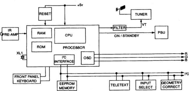
An essential part of the control system is the EEPROM (Electrically Erasable and Programmable Read-Only Memory) used to store all the operating data for the receiver and system in non-volatile form. The data is factory preset but can be overriden by the technician (i.e. when resetting picture geometry after timebase repair) and by the user, for instance when the set is retuned. All communication is via the I2C bus, on which the memory chip has its own address at which serial data can flow in or out of it. Apart from the bus connections, then, the memory needs only supply and ground links, making for a simple package with as few as eight pins. Fig. 22.5 shows the internal architecture of an EEPROM chip with 8 kbit capacity. It is largely self-explanatory except perhaps for the high-voltage section at bottom right. This is an on-board voltage multiplier generating 20 V or 25 V from the 5 V Vcc supply, and is used when it is required to overwrite data in the memory core: the relatively high potential is used to ‘punch through’ to the floating gates of the memory cells, leaving charges which can typically be retained for many decades in the absence of any sustaining potential, hence the term non-volatile. The A0, A1 and A2 lines at the bottom of the diagram are for chip-selection purposes in complex equipment, but are usually grounded in TV sets and videorecorders.
THE I2C BUS
The simplicity of interfacing between the computer, memory and other chips described above is due to the use of a Philips-designed internal data-exchange system called Inter-1C (I2C) bus. A wide range of ICs, from colour and text decoders to audio amplifiers, r.f. modulators and tuners, have unique addresses and I2C decoders to permit their control by automatic or manual means via the control microcomputer and, in the latter case, the user’s remote control handset. We have met several of them in previous chapters of this book. Unlike a true computer system, the control lines in a TV set are quiet for most of the time, so that an eight-wire parallel bus system would hardly be justified in terms of speed; it would also add greatly to the number of pins required on each IC (command and peripheral). The board area required for connections and chips, and the wire/plug/socket count would all increase, as would the cost, complexity and the risk of failure.
The I2C bus is a simple two-wire system, on which the data is sent in serial form. One line (data) is called SDA, and the other, carrying clock pulses for synchronisation, is called SCL. When the bus is not carrying information both lines are held at logic 1 by pull-up resistors to the +ve supply line. All devices connected to the I2C bus must have an open-drain or open-collector to be able to use the wired- AND function.
Although the TV control system described above has only one master in the control microcomputer, the I2C bus is arranged to be bi-directional and to permit the use of more than one master. The pulse generator is called the master, the sending unit is called the transmitter and the receiving unit the slave. The addressing procedure on the I2C bus is such that the first byte of data sent determines which slave has been selected by the master. The most significant seven bits of this byte hold the slave address, and the least significant bit indicates whether the data will be written to or read from the slave. If two masters attempt to use the bus simultaneously, an arbitration process is initiated, in which the master addressing the slave with lower address will predominate; when that transaction is complete, the second master is permitted use of the bus.
For each clock pulse on SCL there is a corresponding data pulse on SDA. The level must be stable on SDA when there is ‘1’ logic level on SCL, so that data on SDA may only be changed while SCL is at 0. The most significant bit is always sent first, and if SDA changes when SCL is at 1, either a start or stop condition is indicated, see Fig. 22.6. An example of I2C bus addressing and data from the microcomputer is given in Figs 22.6(b), (c) and (d). In Fig. 22.6(b) message start is signified by a drop to zero of SDA during an SCL ‘high’. Now comes the 7-bit chip address code 1100000 followed by a 0 to indicate that ‘write into colour decoder IC is required. This is now acknowledged by the slave IC, inviting further data. It comes in the form of a register address 00100010 which is the store for brightness information, Fig. 22.6(c), and its successful receipt is acknowledged on the next clock pulse after the 8-bit word. Finally the required brightness information (set by the user) is loaded into the selected register, overwriting the information already held. Here (Fig. 22.6(d)) the command is ‘full brightness’ corresponding to 00111111. It is loaded on the eight clock pulses of the word and acknowledged on the ninth. The stop (end of message) indication is given by SDA rising during SCL ‘high’. The new information in the brightness control data register raises the d.c. control voltage to the luminance clamp section of the colour decoder chip.
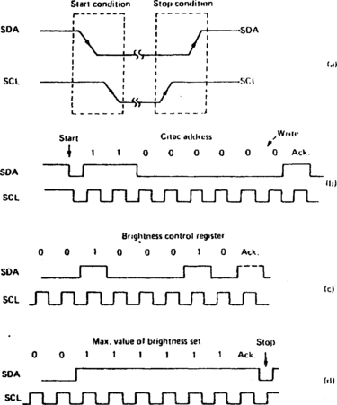
The ‘acknowledge’ procedure does not involve the direct transmission of a pulse from slave to master; the ninth bit is passed out onto the bus by the master as a high (1) but held low (0) by the slave during the appropriate clock pulse if the preceding bits have been received. If the acknowledge bit is allowed to remain high, the master is thus informed that the data has not been accepted … or that no slave occupies the address given. All ‘TV-internal’ peripherals for use with the I2C bus have this acknowledge facility.
SCART SYSTEM AND D2B BUS
Details of the SCART plug/socket connector system are given in Chapter 24. There are two control systems associated with it; the simplest consists of a source switching line at pin 8. By raising a high (+12 V) on this line a source-peripheral (tape- or disc-player, satellite converter, computer etc.) can automatically switch the vision and sound circuits of the TV receiver/monitor to baseband operation in order to transfer signals at CVBS or RGB (plus sound) via the appropriate SCART signal pins. Raising SCART pin 8 to an intermediate level (+6 V) indicates a widescreen programme, and can be used in a TV set to switch scanning standards accordingly. The second control system – on SCART pins 10 and 12 – is more comprehensive, and has much in common with the I2C bus already described, though the serial data flow is slower, and includes a security system to overcome the effects of possible data corruption. This control system is called D2B (Domestic Data Bus), and can be interfaced with I2C (and associated cordless remote control systems) by special transcoding chips.
The two D2B data lines take the form of a floating differential pair, in which logic 1 corresponds to a level above 100 mV and logic 0 to a level below 50 mV. the information is transferred at one of three standard speeds, 110, 2400 and 8300 characters per second, based on clock frequencies of 0.554, 2.217 and 4.436 MHz. The signalling is bi-directional and self-synchronising, with an arbitration system similar to that of I2C. To satisfy the auto-synchronising requirements each bit is more complex than that for a separate-clock pulse system, and consists of an initial period at logic 1; a following period at logic 0 for synchronisation; a period defining the bit value, i.e. 0 or 1; and a final stop period at logic 1.
The formation of a complete D2B message is given in Fig. 22.7. First is a start period at logic 0, then a mode indication to define which of the three speeds is to be used. A 12-bit code to identify the master is now sent, followed by a parity bit for truth checking. The next 12-bit word addresses the intended slave, which will be a piece of AV equipment, a lighting circuit or perhaps even an oven. Parity and acknowledge bits follow, then a 4-bit control signal to define direction of transfer and type of message. Finally comes the control data itself, an 8-bit word to convey a possible 256 different commands, followed by a ‘sign-off set of continuity, parity and acknowledge bits.

In practice the D2B bus protocol has seldom been used, and SCART pins 10 and 12 have been appropriated by equipment manufacturers for other purposes such as satellite-dish positioning drive or data, and power feed lines. Unless one is sure of the control function at both ends (if any), then, it is best to use SCART leads whose pins 10 and 12 are not connected: this avoids the risk of malfunction and damage.
EXTERNAL CONTROL SYSTEMS
Over the years data-exchange protocols have been introduced and developed by individual equipment manufacturers to permit different pieces of AV equipment to ‘talk’ to each other. Some, like the SCART pin 10/12 just described, are ad-hoc systems designed for expediency and thus non-standard, while others (primarily the LANC system designed by Sony) are well established and have been adopted by other manufacturers. Primarily used for edit control (see below), some (LANC, JLIP) are applicable to signal networking and software setting of equipment like camcorders, digital or analogue.
The Sony LANC system uses a single serial data link with address, mode, data status and command bytes, broadly similar to the I2C and D2B buses already described, but not directly compatible with them; it connects via a 5-pin plug or a miniature jack plug, and is very versatile. Panasonic’s edit system is not so developed as LANC; its operation is largely confined to Panasonic videorecorders and camcorders, and ‘freelance’ makes of edit controllers. Again serial data is used, here in 5-pin or 11-pin special connecting plugs and leads.
JVC have a system called JLIP (Joint Level Interface Protocol) which is primarily designed for remote control and edit functions using a PC. It uses a simple serial data format with eight data, one start, one stop and one parity bit, using a 3.5 mm mini-jack plug/socket having four connections: one unused, one ground, one data send and one data receive.
None of these communication systems is compatible with any other, which generally means that the equipment at each end of the link must be of the same (or allied) make.
INTERACTIVE VIDEO WITH DISCS
The use of a separate code to identify each individual chapter, section and frame on a Laservision or DVD disc (Chapter 20) opens the way to a whole new system of controlling replay picture sequencing by an external computer, which can generate picture and chapter addresses for the disc player’s syscon. The computer program determines the order and rate of change of the images, and is itself under a degree of control by the viewer – hence the term interactive. In an interactive learning programme at any level from primary school to university, the student’s progress will depend on his own abilities, as reflected by his answer (or multiple-answer choice) to the questions presented to him. In a simulation exercise for car drivers, aircraft pilots or railway signalmen the results of their actions are graphically displayed in a situation representing, if necessary, the actual working environment involved. For computer shopping the disc’s picture code number can be passed over a telephone or other feedback route to identify and order goods from a catalogue on video disc.
The master computer links up with the disc player’s syscon via a multi-pin socket on the player, typically to standard RS232 interface specification. The presence of some ‘local intelligence’ in the disc player’s syscon microprocessor is fully used with feedback passing to the control micro. Extensions of the technique include the possibility of superimposing computer- and disc-sourced pictures, alpha-numerics and graphics for advanced learning programmes, computer-aided design (CAD) and very advanced TV games with detailed and realistic settings.
VIDEORECORDER EDIT CONTROLLERS
In post-production editing of videotaped material the operator has two roles – an aesthetic and a ‘mechanical’ one. To help with the latter, professional editing studios have long had available automatic editing systems, in which the master copy is assembled in a recorder whose record-pause function is automatically controlled by a microcomputer-based auto-editor. It works from a software program in which the edit-in and edit-out points of the visual and sound material from one or more ‘source’ playback machines are stored. The reference points for these come from cue codes or true frame codes recorded on longitudinal or helical video tape tracks.
These techniques are now available in domestic hardware for ‘home-movie’ enthusiasts. These less sophisticated (but still microcomputer-controlled) auto-editors require access to the pause control of the assembly recorder and the control input jacks of the source machine(s). The simpler types operate by counting field pulses from some chosen ‘start’ reference point in each source tape. More precise editing, down to single-frame accuracy, can be achieved in a domestic situation by the use of timecoding, typically built into the more expensive camcorders. For VHS-based formats the system is called VITC (Vertical Interval Time Code) and consists of teletext-type data recorded in the field blanking interval of the video signal on tape. For Video 8-based formats RCTC (Rewritable Consumer Time Code) is used, in which the timecode is written onto tape separate from the video signal itself, in an extension of each tape track at the beginning of head-scan, see Fig. 22.8. In both cases one code is recorded per TV field, containing data for programme hours, minutes, seconds and frames: this can be used to establish precise in- and out-edit points, stored as described above in an EDL – Edit Decision List. From this list both source and destination decks can be manipulated (the former for play, forward, rewind, and the latter for record and pause) to assemble a master tape from the raw footage of one or more camcorder tapes. Auto-editors come in stand-alone (Fig. 22.9) and computer-based forms, the latter consisting of software and hardware interfaces/cards for use with ordinary home PCs.
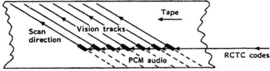
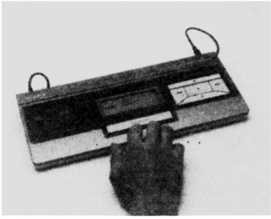
Fig. 22.9 A domestic edit controller by Sony. ft automatically runs a pre-programmed editing sequence
The composition of a master recording direct from another tape as described above is called linear or on-line editing. An alternative method is non-linear/off-line editing, in which the wanted programme segments are stored on the hard disc(s) of a home computer using MPEG data-compression technology similar to that described in Chapter 12. As with the DVC system covered in Chapter 19 the compression ratio is not so great as for broadcast DTV systems, and much computing power and hard disc space is required for this type of picture storage and manipulation. Some DVC-format camcorders (see Chapter 19) have IEE1394 (‘Firewire’) interfaces, by which the signal data can be passed between cameras, decks, computers, printers etc. without being converted to analogue form.