
So far we have shown you some of the basic features of Linux, but one of the most critical features is networking. It is via networking that your host talks to other hosts and your applications communicate with your users and the world. In this chapter, we will describe how to set up your host’s networking and then how to protect that network from attackers using a firewall.
Note
A firewall is a series of rules that control access to your host through the network.
We will teach you about how to configure your network cards or interfaces and how to give them IP (Internet Protocol) addresses. You will learn how to connect to other networks and how to troubleshoot your connections.
We will also be looking at a software application called Netfilter , which is a firewall common to all Linux distributions. You will learn how to manage a firewall and how to write firewall rules. To do this, we will introduce you to Netfilter’s management interface, iptables. We will also show you how to use iptables tools like Firewalld and ufw. Finally, we will also show you how you can use TCP Wrappers to secure daemons running on your host and then set up a PPPOE (Point-to-Point Protocol over Ethernet) connection to an ISP (Internet Service Provider) with Linux.
Throughout this chapter, we will be using networking terminology. We don’t expect you to be a networking expert, but we have assumed you do have some basic knowledge. If you don’t feel that you know enough, we recommend you check out these sites and tutorials:
Note
iptables is used to protect your network services. You will learn more about how to run network services like DNS (Domain Name System) and DHCP (Dynamic Host Configuration Protocol) on your host in Chapter 9.
Introduction to Networks and Networking
Networks are made of both hardware and software. They vary in complexity depending on their size and the level of interconnectedness they require. In a small business you will probably have a simple network. You may have a web server and mail server, and you will probably have a file/print server (sometimes all these servers are actually one host). Undoubtedly, you will have a connection to the Internet, and you will probably want to share that connection with others in your organization.
The nature of your business and the work you do will heavily dictate how you choose to set up your network. Many businesses these days make good use of SaaS (Software as a Service) providers to give them certain business functions such as e-mail, file storage, and access. These businesses can have simple network requirements. Alternatively a business that is starting out often has only one main server that pretty much does all the functions the business requires. It could be a DHCP, DNS, file, mail, and web server all rolled into one. Those familiar with Microsoft products would regard this as similar to a product like Windows Small Business Server. But as that business grows, it will probably begin to move some of these combined functions to its own hosts. Very few larger businesses would trust their entire company IT (information technology) infrastructure to an individual host that has so many roles. This single point of failure should to be avoided where possible, but a small business rarely has the luxury of having a host for each service it wishes to provide.
Caution
If your business does have single points of failure, like many services on one host, backup and recovery become critical. Losing your data could be a disaster for your business, so you should always have backups and the ability to recover your hosts and data. See Chapter 13 for details of how to implement a backup and recovery strategy for your organization.
Then there are the interconnecting pieces of hardware you may require. If you are connecting users in your office to a single network, you will need cables, patch panels switches, and most likely a wireless access point that can create a wireless network.
Caution
Wireless networks are a useful and cheap way to spread your network. They don’t require expensive cabling and switches, and your staff can be a bit more mobile in the office. They present some challenges, however. It should be very common knowledge that wireless networks can allow attackers to connect and sniff your network if inappropriately secured, and they don’t perform as well as wired networks (those with physical cables). For example, it is still much faster to transfer large amounts of data over wired connections rather than over wireless connections. If you’re considering a wireless network for your business, we recommend you read the information at http://en.wikipedia.org/wiki/Wireless_security , https://www.fcc.gov/consumers/guides/protecting-your-wireless-network , and https://www.communications.gov.au/what-we-do/internet/stay-smart-online/computers/secure-your-internet-connection .
We’re going to start by explaining how to configure networking on a single host and introduce you to the tools and commands you will need to configure a broader network.
In order to show you how to configure a network, we’re going to use an example network that we have created. You can see this example network in Figure 7-1.
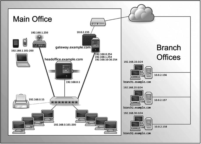
Figure 7-1. Our example network
Here is our complete network diagram. By the end of this chapter, this diagram will not be as daunting as it may appear now. We are going to take you through what the components of this are and how they are configured. We will also explain what all those IP addresses are for and how we can block and move from one network to another.
In this chapter, we will show you how to configure elements of our example network. We will configure a firewall/router host we’re going to call gateway.example.com. It has multiple IP addresses, one for every network it acts as a router for: 192.168.0.254 on our internal network, 192.168.1.254 on our wireless network, and an external IP address of 10.0.2.155.
We will also configure a main server that we’re going to call headoffice.example.com. It will have the IP address of 192.168.0.1 on our internal network. It will route to other networks, like our wireless network, branches, and the Internet via the gateway.example.com host.
As you can see, we have divided the network into separate segments, and we have chosen different network addresses to show this. As we mentioned, our wireless network has the network address of 192.168.1.0/24 and is facilitated by a wireless access point with the IP address of 192.168.1.250.
Note
There are a few ways you can assign an IP address to a computer. You can configure it manually, allowing it to request a random IP in a pool of addresses, and allowing it to request an assigned IP address that it is guaranteed to get. For important IP addresses like network gateways you should always manually configure it or make sure they always receive a known guaranteed address. More on the last option when we talk about DHCP in Chapter 10.
Our branch offices each have a separate network address, and they range from 192.168.10.0/24 to 192.168.30.0/24. This gives us 254 possible nodes (or devices) in each branch office, with the ability to expand them if required.
We also have a local wired network, and this has the network address of 192.168.0.0/24. The main server, headoffice.example.com with IP address 192.168.0.1, will be able to communicate to the branch offices via the VPN networks we will establish from that host to those remote branches (we will explain VPNs in Chapter 15).
The desktops in our local wired network have been given a pool of addresses to use in a range of 192.168.0.101–192.168.0.200. This allows for 100 nodes and can be expanded upon if need be.
In reality, for a network of this size, we would probably have many more servers, and they would possibly be decentralized by placing servers in the branch offices. However, for the purpose of this chapter, we are going to concentrate on the scenario presented in Figure 7-2, in which you can see we have broken down our network into a smaller module.
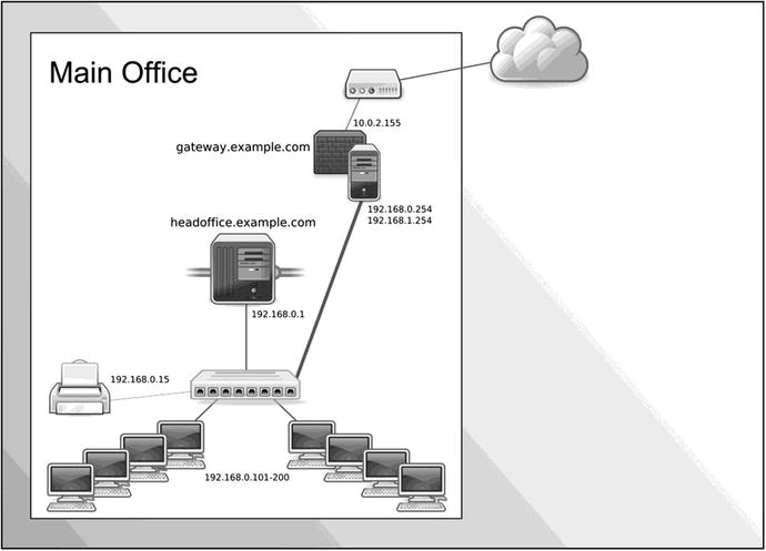
Figure 7-2. The local wired network
Here we can concentrate on building the principal servers for our office, gateway.example.com and headoffice.example.com.
We will show you how to set up a PPPoE connection on the gateway.example.com host to act as a firewall/router host to our ISP and the Internet.
Note
PPPoE is a method used for connecting from ADSL modems to the Internet.
Our main host, headoffice.example.com, will serve mail, web, and DNS services to the public (as we will show you in Chapters 10, 11, and 12).
We will use our gateway.example.com firewall host to accept and route traffic from the Internet through our internal network to our main host. The head-office host will also provide DNS, DHCP, NTP (Network Time Protocol), SMTP (Simple Mail Transfer Protocol), IMAP (Internet Message Access Protocol), HTTP (Hypertext Transfer Protocol), and HTTPS (Hypertext Transfer Protocol Secure) services to our local network. We will also show you how to route traffic from one host to another host in our network. Let’s get started by looking at setting up our interfaces.
Getting Started with Interfaces
The first element of networking we’re going to introduce to you is interface, or network interface. Each of the one or more network cards on your host will be a network interface. When we showed you how to install a distribution in Chapter 2 and configure a network, we were configuring an interface.
Tip
Interfaces are generally in two major states—up and down. Interfaces that are up are active and can be used to receive network traffic. Interfaces that are down are not connected to the network.
What kinds of interfaces can you configure? Modern computer hosts nowadays can easily have more than one network card (or network interface) and sometimes have many hundreds of IP addresses. An interface can have many aliases, or you can bond or team two or more interfaces together to appear as one interface.
Linux gives you the ability to have multiple IP addresses on a single interface. The interface uses the same Mac address for all IP addresses. A bonded, or teamed, interface consists of two or more network interfaces appearing as a single interface. This can be used to provide greater fault tolerance or increased bandwidth for the interface. A bonded interface can also have many IP addresses. We will expand on this a little further on in the sections “Network Configuration Files for CentOS” and “Network Configuration Files for Ubuntu.”
Each of your network interfaces will probably have at least one IP address assigned to it. We will start this introduction to interfaces by demonstrating a simple tool called ip from the iproute (CentOS) or iproute2 (Ubuntu) package that can be used to view and change the status and configuration of your interfaces. The ip tool, in its simplest form, can be used like the ipconfig command on Microsoft Windows.
The ip command is a very powerful utility and can be used to configure all your networking. The ip command works on different network “objects.” Each ip object deals with a particular part of your networking. If you type ip help, you get a list of the different components you can manage.
In Figure 7-3 we can see the output of the ip help command and you can see that we can use it to configure many parts of our networking stack. The ip command has the following basic syntax:
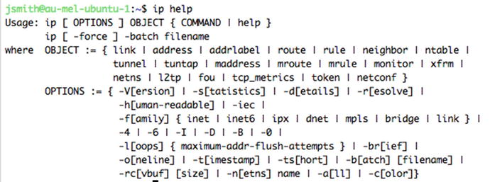
Figure 7-3. ip help command
ip [ OPTIONS ] OBJECT { COMMAND | help }The most common object you will work on are link, address, and route. Table 7-1 describes these and the rest of the objects for this command.
Table 7-1. Describing the Full List of Objects in the ip Command
Object | Description |
|---|---|
link | The network device |
address | The address of the interface (IPv4 or IPv6) |
addrlabel | Allows you to apply labels to addresses |
l2tp | Tunneling Ethernet over IP |
maddress | Multicast address |
monitor | Netlink message monitoring |
mroute | Multicast routing cache entry |
mrule | Managing rules in multicast routing policy |
neighbor | ARP or NDISC cache entry |
netns | Manage network namespaces |
ntable | Manage the neighbor cache’s operation |
route | Routing table entry |
rule | Rule in the routing policy database |
tcp_metrics | Manage tcp metrics |
tunnel | Tunnel over IP |
tuntap | Manage TUN/TAP devices |
xfrm | Manage IPSec policies |
There are man pages for each of these objects that go further to describe their uses. For example, more information about the ip address command can be found by entering $ man ip-address. You can see all the appropriate man pages by looking at the SEE ALSO section of the $ man ip page.
We are now going to show you how to use the ip command to discover more about your network interfaces. To display the IP address information of all the interfaces on a host, we use this command:
$ ip address showRunning the ip command with the address show option displays all interfaces on your host and their current status and configuration. We could also use the shortened alias ip addr show.
The foregoing will list all the host interfaces and their addresses. To make it easier to explore the configuration of a particular interface, you can also display a single interface, as follows:
Listing 7-1. Status Output of ip addr show on an Active Interface
$ ip addr show enp0s32: enp0s3: <BROADCAST,MULTICAST,UP,LOWER_UP> mtu 1500 qdisc pfifo_fast state UP group default qlen 1000link/ether 08:00:27:a4:da:6b brd ff:ff:ff:ff:ff:ffinet 192.168.0.1/24 brd 192.168.0.255 scope global enp0s3valid_lft forever preferred_lft foreverinet6 fe80::a00:27ff:fea4:da6b/64 scope linkvalid_lft forever preferred_lft forever
The first line shows the status of the interface. The 2: is just an ordering number. The enp0s3 is the device name of the interface. In between the <> are the interface flags. BROADCAST means we can send traffic to all other hosts on the link, MULTICAST means we can send and receive multicast packets, UP means the device is functioning. LOWER UP indicates that the cable or the underlying link is up.
In the same line we have some other information. The state of the interface is currently UP. This means that the interface is active and can potentially receive traffic if it is properly configured. The MTU, or maximum transmission unit , is the maximum size in bytes of packets on your network; 1,500 is the common default. The qdisc pfifo_fast is the queuing discipline, which is how the data is sent out to the network; this is first in, first out and the default. You can also group interfaces together and perform actions on them; this shows that ours is in the default group. Finally qlen is the Ethernet buffer transmit queue length and it can be referred as the speed of your network card, 1,000 mbits in this case.
The output also shows three important pieces of information, the ipv4 address, the ipv6, address and the MAC (Media Access Control) address of this host. It has an IP address assigned to it, inet 192.168.0.1, and we explain that shortly. The next line is an IPv6 address, here inet6 fe80::a00:27ff:fea4:da6b/64, that is a link-local IPv6 address derived from the MAC address. Every Ethernet network card has a unique hardware identifier that is used to identify it and communicate with other Ethernet devices. This MAC address can be seen in first line of output (link/ether 08:00:27:a4:da:6b in this example).
Note
See https://wiki.ubuntu.com/IPv6 or www.internetsociety.org/deploy360/ipv6/basics/ for more information on IPv6.
The IPv6 address can be used to communicate with other hosts using stateless address autoconfiguration (SLAAC). SLAAC is used quite often by devices like PDAs and mobile phones and requires a less complicated infrastructure to communicate with other devices on the local network. This is because each SLAAC IPv6 address is intended to be world routable and is combined with the network address to make a universally unique address.
Note
See http://www.ipv6.com/articles/general/Stateless-Auto- Configuration.htm for more information on stateless autoconfiguration and IPv6.
In the next example we are going to look at a network device we have just attached to our host. This does not currently have an IP address associated with it:
$ ip addr show3: enp0s8: <BROADCAST,MULTICAST> mtu 1500 qdisc noop state DOWN group default qlen 1000link/ether 08:00:27:13:3c:00 brd ff:ff:ff:ff:ff:ff
Comparing it to our previous output you can immediately notice that the state is DOWN and that we can only see a MAC address that has been assigned to the network device enp0s8. Let’s now see what happens when we bring up the device or link. We do that by using the following ip link subcommand and then ip addr show enp0s8:
$ sudo ip link set dev enp0s8 up...3: enp0s8: <BROADCAST,MULTICAST,UP,LOWER_UP> mtu 1500 qdisc pfifo_fast state UP group default qlen 1000link/ether 08:00:27:13:3c:00 brd ff:ff:ff:ff:ff:ffinet6 fe80::a00:27ff:fe13:3c00/64 scope linkvalid_lft forever preferred_lft forever
Device enp0s8now is UP and has been assigned a qdisc (pfifo_fast). Interestingly we also have an IPv6-generated IP address, which is based on the MAC address that is assigned.
To bring down the interface, you would use the following:
$ sudo ip link set dev enp0s8 downYou can validate what you have down by issuing the following command which provides just the link status:
$ sudo ip link show enp0s83: enp0s8: <BROADCAST,MULTICAST> mtu 1500 qdisc pfifo_fast state DOWN mode DEFAULT group default qlen 1000link/ether 08:00:27:13:3c:00 brd ff:ff:ff:ff:ff:ff
Let’s now add an IPv4 address to our network device. We have checked on our network and IP address 192.168.10.1 is available. Let’s add that to device enp0s8.
$ sudo ip addr add 192.168.10.1/24 dev enp0s8Looking at the result of $ sudo ip addr show enp0s8 we see that we have the following line added to our output:
inet 192.168.10.1/24 scope global enp0s8This what we expect, but the status is still down, so we would now issue the following command:
$ sudo ip link set dev enp0s8 upAnd on viewing the output of ip addr show enp0s8 again, it will now be in the UP state and ready to send and receive traffic on the at interface. It should now look similar to Listing 7-1.
We can also remove an interface. When we “down” a link, we don’t remove the IP address. To do that we would issue the following:
$ sudo ip addr del 192.168.10.1/24 dev enp0s8The link is still up and the IPv4 address has gone if you now show the interface. You should notice that the IPv6 address will be available as long as the link is UP. To disable the IPv6 interface you will need to down the link.
Note
Changes to your interfaces using the ip command are not persistent across reboots; when you reboot, you will lose any changes. We will explain shortly how to permanently apply your changes to your host.
Managing Interfaces
As we have said, using the ip command is good for adding and managing interfaces on the fly, but we need to also be able to permanently configure interfaces too. There are several ways to do that on Linux. You can choose to either use the graphical user interfaces (GUIs ) or run directly from the command line. You can also write directly to network files if you wish.
CentOS and Ubuntu can manage networking differently. CentOS now uses NetworkManager to manage its networks. Ubuntu can use NetworkManager but it is not installed by default. NetworkManager is a daemon process that manages the network connections and services. It is installed on Ubuntu as part of the Unity desktop or you can install it on its own. NetworkManager will integrate with the older style (LSB) files for managing network interfaces too via a LSB network service.
NetworkManager integrates and configures Domain Name System (DNS) resolution via the Dnsmasq program (a local DNS server) and handles configuring and setting up VPN and wireless connections.
We talked about systemd and about about the multi-user.target in Chapter 6 and this is what brings up the NetworkManager. NetworkManager has plug-ins that give it the ability to manage your network configuration files. These are ifcfg-rh and ifupdown which handle Red Hat-style and Debian-style scripts, respectively. You can disable the management of your interfaces via NetworkManager in Red Hat-style hosts by setting the NM_CONTROLLED=’no’ in the network connection profile file (explained shortly). In Debian-style hosts NetworkManager is disabled for managing interfaces listed in /etc/network/interfaces unless you specifically change the following in the /etc/NetworkManager/NetworkManager.conf to:
[ifupdown]managed=true
Some people choose not to run NetworkManager because they find it too intrusive and they prefer to manage their networks themselves. NetworkManager was conceived to make networking “just work” and your mileage may vary, but a lot of work has gone into it since its inception and it is definitely much better than it was when it started out.
NetworkManager also provides some CLI (command-line interface ) programs to help manage your configuration.
nmcli–controls and reports status of NetworkManager
nmtui–text-based user interface for managing NetworkManager
We are going to show you more on nmcli and nmtui later in this Chapter. For more information on NetworkManager, you can see the following:
Managing Networks via a GUI
If you are using a desktop to manage your server you can use a GUI to manage your network configuration. With CentOS we access the networking settings via the Applications ➤ System Tools ➤ Settings.
In Figure 7-4 we can see the configured networks on our system. In the left-hand panel you can select the devices that attached to the system, here our network interface is called “Wired .” The gear cog in the bottom right allows you to access the configuration. You can turn on or off the interface with the on-off toggle button. If you wish to add another type of interface, like teamed or bonded or VPN interface, you should select the + at the bottom of the left panel.
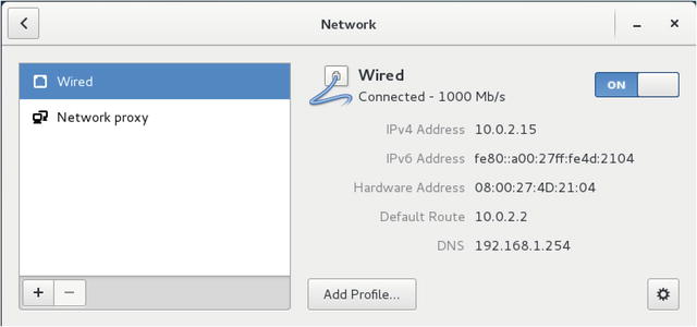
Figure 7-4. CentOS network settings
If we were to add a new interface and come there to configure it, we will see the interfaces listed in the left panel by their device names, like enp0s8. If you choose to configure one of the interfaces you can see that the options are similar to what we saw when we were installing our server.
We have seen this before; in Figure 7-5 we are adding the 192.168.10.1 address. Again we can choose to manually configure the interface, or allow it to be configured via DHCP with the drop-down option.
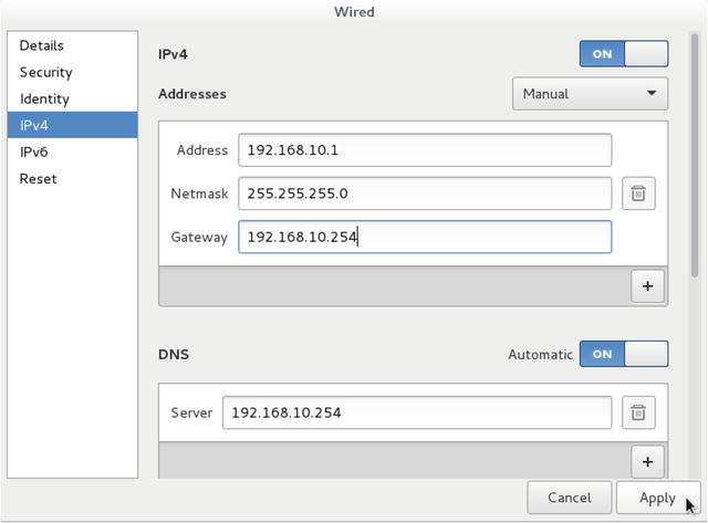
Figure 7-5. Adding an IP address in CentOS network settings
We can do the same thing if you are running the Ubuntu desktop to manage your server. In Figure 7-6 we are using the Unity Desktop’s search facility to find the network settings.
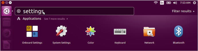
Figure 7-6. Network settings in Ubuntu
On selecting Network in Figure 7-6 we get a similar user interface to configure our networks as we did with CentOS. In Figure 7-7 we can see that you plug in the same information in to this interface as we did in Figure 7-5.
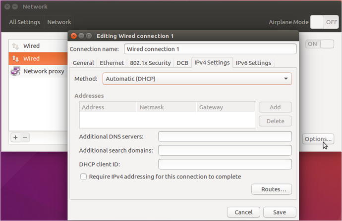
Figure 7-7. Configuring a network interface in Ubuntu
In Figure 7-7 we again can choose to use DHCP or manually configure the interface. Using the user interface to configure your network interfaces persist across reboots.
Let’s now view the other way to persist the network configuration with network configuration files and scripts.
Configure Interfaces with nmtui
The curses-based configuration tool that comes with NetworkManager is designed to work on any type of terminal. You can create and manage interfaces as well as set the hostname via this terminal user interface (tui).
In this exercise we are going to run through the nmtui program to configure our newly attached enp0s8 Ethernet device. We can find the device name for our new interface with the use of dmesg.
$ sudo dmesg |grep enp[ 6.903532] IPv6: ADDRCONF(NETDEV_UP): enp0s8: link is not ready
We will use this information shortly. To start it you issue $ sudo nmtui.
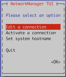
Figure 7-8. Edit a connection
Here we select Edit a connection.
In Figure 7-9 we add select Add to add our new interface.
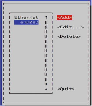
Figure 7-9. Add a connection
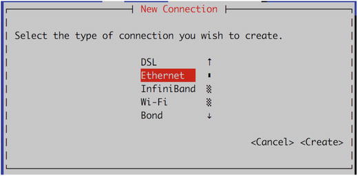
Figure 7-10. Type of interface, Ethernet
Here we select the type of interface we wish to add. There are several options to choose, including DSL for connecting to your ISP, Wi-Fi, and others like VLAN and team interfaces. We are going to select Ethernet.
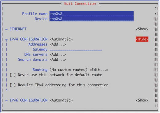
Figure 7-11. Add in our interface
We have provided a profile name; this name can be anything you wish, but it can often be helpful to name it something meaningful as you can use this profile name when working with the sister command, nmcli. In our case we have just named it the same as the device name which we have added to the Device section.
We can set an IP address or we can allow our interface to receive one from a DHCP server, which is what we decided to do. However, adding the IP address is simply like we have done previously. We can arrow down to <OK> and exit.
Configuring Interfaces with nmcli
There is yet another way to we can configure our interfaces. It is with the utility called nmcli. This is a very powerful tool that works with and configures NetworkManager configurations.
With this tool we can create, display, edit, and bring up and down interfaces. Let’s take the time to explore this utility first.
We have spoken before about NetworkManager profiles. These are names given to interfaces. To display the current connection information using nmcli we would issue the following:
$ sudo nmcli connection showNAME UUID TYPE DEVICEenp0s3 da717740-45eb-4c45-b324-7d78006bb657 802-3-ethernet enp0s3
There are several shortcuts for nmcli, like “c” for connection and “d” for device. To manage the actual device (connect, disconnect, delete) you use the device subcommands.
$ sudo nmcli d statusDEVICE TYPE STATE CONNECTIONenp0s3 ethernet connected enp0s3lo loopback unmanaged --
The nmcli command takes the following format:
$ nmcli <OPTIONS> <OBJECT> <COMMAND|HELP>So if you need help to remember how to use the add command on the connection object you can type
$ nmcli connection add helpUsage: nmcli connection add { ARGUMENTS | help }....
What we are going to do next is add a team interface to our CentOS host. A team interface is an aggregated interface made up of two or more links. It can provide greater throughput or link redundancy than a single interface. It can support active/passive, LACP (Link Aggregation Control Protocol), and VLANs (Virtual Local Area Networks) and other protocols.
A teaming has two main parts, a teamd daemon and runners. The teamd daemon manages the API (application programming interface) between the network interfaces and the kernel. The runners are another word for modules that provide the code that implements the particular features, like active/passive and VLANs.
We are going add two devices to create a team interface with an active/passive runner. These will be enp0s8 and enp0s9.
$ sudo nmcli device statusDEVICE TYPE STATE CONNECTIONenp0s8 ethernet disconnected --enp0s9 ethernet disconnected --
To begin we add the team interface (team0) with the command in Listing 7-2.
Listing 7-2. Adding team0 Interface
sudo nmcli c add type team con-name team0 ifname team0 config'{"device": "team0", "runner": {"name":"activebackup"}}' ip4 192.168.10.10 gw4 192.168.10.254
In Listing 7-2 we have used the nmcli command to add a team interface and assigned it the IP address 192.168.10.10 and the gateway address of 192.168.10.254. We did this by adding (add) a connection (c) type of team. We have given this interface the name of team0 (ifname) and a profile name of team0 (con-name) also.
With a teamed interface we need to provide a JSON configuration to describe the runner we wish to use. This can either be in a JSON file or on the command line as we have above. There are further examples of the settings that you can use in man 5 teamd.conf. In Listing 7-2 we have provided the minimum required and that is the device and the runner.
What this creates is a file called /etc/sysconfig/network-scripts/ifcfg-team0 and we can see that that has the following details:
DEVICE=team0TEAM_CONFIG="{"device": "team0", "runner": {"name":"activebackup"}}"DEVICETYPE=TeamBOOTPROTO=noneIPADDR=192.168.10.10PREFIX=32GATEWAY=192.168.10.254DEFROUTE=yesIPV4_FAILURE_FATAL=noIPV6INIT=yesIPV6_AUTOCONF=yesIPV6_DEFROUTE=yesIPV6_PEERDNS=yesIPV6_PEERROUTES=yesIPV6_FAILURE_FATAL=noNAME=team0UUID=2cef1621-4e56-4cb8-84f7-2d613fbc168fONBOOT=yes
We will explain these configuration files shortly, you can see our setting for the team configuration and IP address. We have created the “master” interface and we now have to add “slaves” to it.
We do this with the following commands:
sudo nmcli c add type team-slave con-name team0-port1 ifname enp0s8 master team0Connection 'team0-port1' (4e2f4307-e026-4b1a-b19e-da8f1ad64d7a) successfully added.sudo nmcli c add type team-slave con-name team0-port2 ifname enp0s9 master team0Connection 'team0-port2' (ca1206ce-c0d3-45a5-b793-f10b8c680414) successfully added.
Again we have added a type of team-slave with a connection name of team-port{1,2} and attached these to interface enp0s{8,9} to master team0. Let’s take a look at one of the files that this creates.
/etc/sysconfig/network-scripts/ifcfg-team0-port1NAME=team0-port1UUID=4e2f4307-e026-4b1a-b19e-da8f1ad64d7aDEVICE=enp0s8ONBOOT=yesTEAM_MASTER=team0DEVICETYPE=TeamPort
And now let’s see if they show up in our connection list.
sudo nmcli c showNAME UUID TYPE DEVICEteam0-port1 4e2f4307-e026-4b1a-b19e-da8f1ad64d7a 802-3-ethernet enp0s8team0 2cef1621-4e56-4cb8-84f7-2d613fbc168f team team0team0-port2 ca1206ce-c0d3-45a5-b793-f10b8c680414 802-3-ethernet enp0s9
And the device list now looks as follows:
$ sudo nmcli d status[sudo] password for jsmith:DEVICE TYPE STATE CONNECTIONenp0s8 ethernet connected team0-port1enp0s9 ethernet connected team0-port2team0 team connected team0lo loopback unmanaged --
We will quickly see if we can get a ping response from the interface.
ping 192.168.10.10PING 192.168.10.10 (192.168.10.10) 56(84) bytes of data.64 bytes from 192.168.10.10: icmp_seq=1 ttl=64 time=0.047 ms
So now we have a team interface. You can also manage team interfaces with team tools like teamctl and teamnl. Let’s go on to see more on the configuration files.
Configuring Networks with Network Scripts
Both CentOS and Ubuntu have their network configuration files stored in the /etc directory. CentOS stores its files in a collection of network-related directories under /etc/sysconfig/network-scripts, and Ubuntu stores its files under the /etc/networks directory.
Network Configuration Files for CentOS
As we have said previously, CentOS uses NetworkManager to manage network interfaces as they are plugged in or connect. The CentOS files relating to networking can be found under the /etc/sysconfig directory. The main places to find this information are
The /etc/sysconfig/network file
The /etc/sysconfig/network-scripts directory
The /etc/sysconfig/network file contains global settings and can contain things like HOSTNAME and default GATEWAY. The /etc/sysconfig/network-scripts directory contains all the start-up and shutdown scripts for network interfaces. These files are general copies of files in the /etc/sysconfig/ network-script directory and are created for you by the system-config-network tool.
Taking a look at the contents of the /etc/sysconfig/network-scripts directory, you will see the files shown in Listing 7-3.
Listing 7-3. Files Found in /etc/sysconfig/network-scripts
sudo ls /etc/sysconfig/network-scripts/ifcfg-enp0s3 ifdown-ipv6 ifdown-ppp ifdown-tunnelifup-ipv6 ifup-routes ifup-wireless network-functions-ipv6ifcfg-lo ifdown-eth ifdown-routes ifup ifup-eth ifup-postinit.ipv6-global ifdown ifdown-post ifup-aliasesifup-ppp ifup-tunnel network-functions
In Listing 7-3, you can see a reduced list of the scripts that are used to configure your interfaces and bring them up or down. A variety of files are present.
The files like ifcfg-enp0s3 are configuration files, or connection profiles, for the Ethernet interfaces. The files with the naming convention of if<action>-device, for example, ifdown-ppp, are scripts that are used to control the state (i.e., bring the interface up or down).
We talked about NetworkManager previously. NetworkManager, if it is configured to do so, will read and write to these files. The configuration profile files, like ifcfg-enp0s3, are read in by NetworkManager and will pass off the device name to the ifup script. If the device is already connected and managed by NetworkManager, ifup will use the nmcli to manage the interface. If we have NM_CONTROLLED=”no”, then ifup will use the ip command to manage the interface. Before doing so, it checks to see if this device is already managed by the NetworkManager and if so, it does not attempt to manage the device. To bring up the enp0s3 device you issue the following:
ifup enp0s3Files like network-functions are scripts can that contain functions and variables. Other scripts can source (or include) the functions and variables from network-functions and use them in their scripts.
Let’s take a look at the configuration file for enp0s3, which is called ifcfg-enp0s3. You can see the contents of this file in Listing 7-4.
Listing 7-4. The ifcfg-enp0s3 File
sudo less /etc/sysconfig/network-scripts/ifcfg-enp0s3TYPE="Ethernet"DEVICE="enp0s3"NAME="enp0s3"UUID="fa56e72e-ea22-43ca-9a90-e19d64c0c431"ONBOOT="yes"BOOTPROTO="dhcp"DEFROUTE="yes"PEERDNS="yes"PEERROUTES="yes"IPV4_FAILURE_FATAL="no"IPV6INIT="yes"IPV6_AUTOCONF="yes"IPV6_DEFROUTE="yes"IPV6_PEERDNS="yes"IPV6_PEERROUTES="yes"IPV6_FAILURE_FATAL="no"
In Listing 7-4, you can see a number of configuration options in the form of option=argument. To configure a CentOS interface we set options like the name of device we are managing: DEVICE=”enp0s3”. We use the same value for the name.
The boot protocol, BOOTPROTO=”dhcp”, is set to get its address from DHCP. The UUID (universal unique identifier) of the device is "fa56e72e-ea22-43ca-9a90-e19d64c0c431", and this is a unique identifier assigned to this device and is used by the NetworkManager to map the device. You can declare whether the interface will initialize at boot up by specifying ONBOOT=”yes”. The type of interface is declared by TYPE=”Ethernet”. If you don’t want to initialize our interface with an IPv6 address you can set IPV6INIT to “no”; here it is the default IPV6INIT=”yes”. When PEERDNS=”yes” is declared, it means that /etc/resolv.conf file with name servers provided by the DHCP server. If we set it to no, /etc/resolv.conf will remain unmodified when this interface is brought to an up state. We will explain more about how this works in Chapter 10.
Table 7-2 lists the options you can use in your CentOS interface files.
Table 7-2. Some of the Common Network Configuration File Options, CentOS
Option | Description |
|---|---|
DEVICE | The name of the device you are creating. This will appear in the interface listings. |
BOOTPROTO | The protocol to use when the device starts up. The choices here are static, dhcp, and none. |
ONBOOT | Whether the device is started when the host boots up. |
NETWORK | The network address for this device. |
NETMASK | The netmask for this device. |
IPADDR | The IP address for this device. |
IPV4_FAILURE_FATAL | If set to yes, if we don’t get an IP address from DHCP the ifup-eth script will end immediately |
MASTER | The device to which this device is the SLAVE. |
SLAVE | Whether the device is controlled by the master specified in the MASTER directive. |
NM_CONTROLLED | If set tono, Network manager ignores the device. The default is yes on CentOS. |
DNS{1,2} | DNS host’s IP address (multiple addresses are comma separated). This will be added to /etc/resolv.conf if PEERDNS is set to yes. |
PEERDNS | Setting that determines whether DNS hosts specified in DNS are added to /etc/resolv.conf. If set to yes, they are added. If no, they are not added. |
VLAN | Set this device as a VLAN interface (‘yes’, ‘no’) |
IPV6INIT | Enable or disable the IPv6 configuration for this device. |
The options in Table 7-2 are just some of what can be set in your network connection profile; for a full list of the options you can read the /usr/share/doc/initscripts-<version>/sysconfig.txt, where <version> is the version number of the initscripts package.
Creating Bonded Interfaces
We are now going to take you through how to manually configure a bonded Ethernet device by setting some options in the connection profile file. A bonded Ethernet device can also be referred to as a trunk device. Bonding allows you to use two or more Ethernet ports to act as one interface, giving you expanded bandwidth and some redundancy. In this way you can turn a 1 GiB link into a 2 GiB link for the one virtual interface.
So how would we do this feat? We have two devices attached to our host, enp0s8 and enp0s9. We are going to bond these two devices together so that they appear as one interface, bond0. First we have to configure each device as a SLAVE, and in Listing 7-5 you can see how we have configured enp0s8. The enp0s9 device will be a mirror of this device.
Listing 7-5. The enp0s8 Slave Device Configuration
less /etc/sysconfig/network-scripts/ifcfg-enp0s8DEVICE="enp0s8"NAME="bond0-slave"TYPE="Ethernet"ONBOOT="yes"BOOTPROTO="none"SLAVE="yes"MASTER="bond0"
This is a very simple configuration. We have specified the device we wish to control, enp0s8, and whether we would like it to initialize when we boot up our host by specifying ONBOOT=”yes”. The IP address for this bonded device will attach itself to the bond0 device, not to enp0s8 or enp0s9; therefore, we do not specify a boot protocol here and use the option BOOTPROTO=”none”, instead. The NAME=”bond0-slave” will become clear when we bring up our bonded interface, but it provides an easy-to-read name that NetworkManager will display (remembering that unless we explicitly have NM_CONTROLLED=”no”, NetworkManager will manage our connection).
Next are the two options that add this device to a bonded configuration. The first, SLAVE=”yes”, declares that this device is to be a slave. Next, we declare to which master it belongs by specifying MASTER=”bond0”. The bond0 we are referring to is a device of the same name that we are about to create.
Interface enp0s9 (which is configured in the /etc/sysconfig/network-scripts/ifcfg-enp0s9 file), as we said, will mirror the copy and paste the details from enp0s8. Then we need to change the DEVICE=enp0s8 to DEVICE=enp0s9. The rest can stay the same.
Next we will create our bond0 device file. On CentOS, the configuration details will be kept in a file called /etc/sysconfig/network-scripts/ifcfg-bond0. In Listing 7-6, you see what we need to create a bonded interface.
Listing 7-6. Configuration for a Bonded Interface
[jsmith@au-mel-centos-1∼]$ vi /etc/sysconfig/network-scripts/ifcfg-bond0DEVICE="bond0"NAME="bond0"TYPE="bond"BONDING_MASTER="yes"BONDING_OPTS="mode=1 delayup=0 delaydown=0 miimon=100"BOOTPROTO="none"ONBOOT="yes"NETWORK="192.168.0.0"NETMASK="255.255.255.0"IPADDR="192.168.0.1"
As you can see, it is very similar to a standard Ethernet device file. You need to specify the device name, bond0 in our example, and give it the appropriate network information like its IP address, network, and netmask information. Again, we want this device to be initialized at boot-up.
There are some bonding-specific options listed in Listing 7-6, like BONDING_MASTER and BONDING_OPTS. BONDING_MASTER is fairly straightforward and just means that this is a bonding master interface. BONDING_OPTS allow you to set per interface bonding options to your interface. Let’s look at what we have set in the above.
Mode 1 sets the interface bonding type to active backup, and you can use “mode=active-backup” instead of “mode=1” if you prefer. With active backup, when the active interface fails, the other takes over. This primarily for network card redundancy and not throughput. The miimon is how often (in milliseconds) the interfaces are checked for being active. In high‑availability configurations, when miimon notices that one interface is down, it will activate the remaining interface(s). The delayup and delaydown are settings giving the time period in milliseconds where we should wait to act on changes in the slave state. We have set these to zero and over time we would adjust these as was deemed necessary.
Depending on your network and what kind of bonding you can implement given your network equipment, you can add other options here to give fault tolerance, redundancy, and round‑robin features to your bonded device. For more information, you can look at the documentation provided by the iputils package that manages bonding on CentOS hosts, specifically the /usr/share/doc/iputils-<version>/README.bonding.
What happens when you interface comes up is that your scripts (NetworkManager or ifup-eth scripts) will insert the bonding module into the kernel. The bonding module allows the kernel to know how to handle bonded interfaces and it can be also be referred to as a driver for the kernel. The low-level tools that manage bonding interfaces, like ifenslave from the iputils package, require the bonding module to be loaded prior to bonding your interface. If you want to check to see if your bonding module is already loaded in the kernel you can issue the following, and if it is, you will see something like this:
lsmod |grep bondingbonding 136705 0
If it is not, don’t worry. We will check again after we bring up our interfaces. You can use the modprobe command to insert the bonding module if you wish.
sudo /usr/sbin/modprobe bonding Tip
The modprobecommand is the smarter way to insert modules (instead of the insmod command) into the kernel as it handles dependencies.
We are now going to bring up the bond0 device or master interface. It is important to follow the starting order of your interfaces; for instance, when you start the master interface first, your slave interfaces are not automatically started, but when you start your slave interface, your master is automatically started. We are setting a static IP address, and our master will start IP connections and respond to “ping” even though the slave interfaces are not up. In DHCP, the master will not get an IP until the slaves are up. Also, remember that NetworkManager is going to manage these interfaces so we will begin using some of the nmcli commands to show our connections but you can also use the ip command we saw earlier.
When we make changes to our interface scripts, like ifcfg-enp0s8, we need to tell NetworkManager to reread it. We can be specific about the interface file to reread but in this case we are going to get it reread all of them by issuing
sudo nmcli connection reloadTip
This can be shortened to nmcli c r as many of the commands can just take the first letter of the subcommand.
Let’s now check the current state of our interfaces. With nmcli we issue the following:
sudo nmcli device statusDEVICE TYPE STATE CONNECTIONenp0s8 ethernet disconnected --enp0s9 ethernet disconnected --
This shows our devices are currently in the disconnected state. We are now going to bring up our master (bond0) interface by starting our slave interfaces. We can do this via the nmcli command too as follows:
sudo nmcli device connect enp0s8Device 'enp0s8' successfully activated with '00cb8299-feb9-55b6-a378-3fdc720e0bc6'.sudo nmcli device statusDEVICE TYPE STATE CONNECTIONbond0 bond connected bond0enp0s3 ethernet connected enp0s3enp0s8 ethernet connected bond0-slaveenp0s9 ethernet disconnected --lo loopback unmanaged --sudo nmcli device connect enp0s9sudo nmcli device statusDEVICE TYPE STATE CONNECTIONbond0 bond connected bond0enp0s3 ethernet connected enp0s3enp0s8 ethernet connected bond0-slaveenp0s9 ethernet connected bond0-slavelo loopback unmanaged --
Our first command was issued to connect our enp0s8 device. When that connection can up so did our bond0 device but our enp0s9 device was still disconnected. We then brought up our enp0s9 device.
And just quickly, we can validate that our bonding driver has been loaded into the kernel by issuing the following again:
lsmod |grep bondingbonding 136705 0
If we wanted to bring down the bond interface we could issue the following:
sudo nmcli connection down bond0Connection 'bond0' successfully deactivated (D-Bus active path: /org/freedesktop/NetworkManager/ActiveConnection/6)sudo nmcli device statusDEVICE TYPE STATE CONNECTIONenp0s3 ethernet connected enp0s3enp0s8 ethernet disconnected --enp0s9 ethernet disconnected --
You can see here that bringing down the bond0 interface has disconnected the two slaves as well.
We can also view your new bonded device by issuing the /sbin/ip addr show command, which will produce the following output:
3: enp0s8: <BROADCAST,MULTICAST,SLAVE,UP,LOWER_UP>mtu 1500 qdisc pfifo_fast master bond0 state UP qlen 1000link/ether 08:00:27:71:c3:d8 brd ff:ff:ff:ff:ff:ff4: enp0s9: <BROADCAST,MULTICAST,SLAVE,UP,LOWER_UP>mtu 1500 qdisc pfifo_fast master bond0 state UP qlen 1000link/ether 08:00:27:71:c3:d8 brd ff:ff:ff:ff:ff:ff8: bond0: <BROADCAST,MULTICAST,MASTER,UP,LOWER_UP>mtu 1500 qdisc noqueue state UPlink/ether 08:00:27:71:c3:d8 brd ff:ff:ff:ff:ff:ffinet 192.168.0.1/24 brd 192.168.0.255 scope global bond0valid_lft forever preferred_lft foreverinet6 fe80::a00:27ff:fe71:c3d8/64 scope linkvalid_lft forever preferred_lft forever
If you look at the interface description of enp0s8 and enp0s9, you can see that they are both set to SLAVE, and you can see that bond0 is set to MASTER. Neither slave has an IP address associated with it. It is the bond0 interface that has the IP address associated with it.
Adding Multiple IP Addresses to Interfaces
We can add multiple addresses to an interface. They do not have to be in the same network and can be used to route traffic from different networks across your host. To do this we can edit our network profile. Let’s again look at our CentOS host and its enp0s3 profile.
We can use the nmcli command to do this. To do that we have to modify an existing interface. First we see the available interfaces with the following:
sudo nmcli c senp0s3 da717740-45eb-4c45-b324-7d78006bb657 802-3-ethernet enp0s3
Take note of the device uuid (da717740-45eb-4c45-b324-7d78006bb657), we can use that to refer to our interface. We are going to use the connection object to modify our interface and add multiple IP addresses as follows:
sudo nmcli con mod da717740-45eb-4c45-b324-7d78006bb657 ipv4.addresses '192.168.14.10/24, 172.10.2.1/16, 10.2.2.2/8'If we now look inside the /etc/sysconfig/network-script/ifcfg-enp0s3 file we can see we have our IP addresses added.
TYPE=EthernetBOOTPROTO=dhcpDEFROUTE=yes<snip>NAME=enp0s3UUID=da717740-45eb-4c45-b324-7d78006bb657DEVICE=enp0s3ONBOOT=yes<snip>IPV6_PEERROUTES=yesIPADDR=192.168.14.10PREFIX=24IPADDR1=172.10.2.1PREFIX1=16IPADDR2=10.2.2.2PREFIX2=8
Here you can see we have added two IPv4 addresses, IPADDR, IPADDR1 and IPADDR2. We can use the PREFIX, PREFIX1, and PREFIX2 to provide the network mask.
To refresh the interface to bring it up with the new addresses. We do that with nmcli too.
sudo nmcli con up enp0s3Connection successfully activated (D-Bus active path: /org/freedesktop/NetworkManager/ActiveConnection/2685)
We can now see the new addresses as follows:
ip addr show enp0s3 |grep inetinet 10.0.2.15/24 brd 10.0.2.255 scope global dynamic enp0s3inet 192.168.14.10/24 brd 192.168.14.255 scope global enp0s3inet 172.10.2.1/16 brd 172.10.255.255 scope global enp0s3inet 10.2.2.2/8 brd 10.255.255.255 scope global enp0s3inet6 fe80::a00:27ff:feb2:9245/64 scope link
The other way to add an alias is to use a script to assign IP addresses when your host boots up. We can add something like this into our rc.local file:
/etc/rc.d/rc.local/sbin/ip addr add 192.168.0.24/24 brd 192.168.0.255 dev enp0s3/sbin/ip addr add 192.168.0.25/24 brd 192.168.0.255 dev enp0s3/sbin/ip addr add 192.168.0.26/24 brd 192.168.0.255 dev enp0s3
In the foregoing we are adding the IPv4 addresses 192.168.0.24-26 to our enp0s3 address when our host is rebooted. The /etc/rc.d/rc.local file needs to have the execute bit set (chmod +x rc.local) and because we are running systemd and not SysVInit we need to make sure that systemd will execute it when we restart our system. If you remember from Chapter 6 we do that by executing the following:
sudo systemctl enable rc-local.serviceThat is how we can manage different types of interfaces under CentOS. Now let’s look how we do this under Ubuntu.
Network Configuration Files for Ubuntu
Ubuntu has a similar directory for its network files in /etc/network. It contains the network files and scripts that are used by Ubuntu to set up your networking. As we described earlier, Ubuntu stores interface information in the file /etc/network/interfaces. It contains all the interface information for any configured interface.
An interface that uses DHCP can be as simple as the following:
# The primary network interfaceauto enp0s3iface enp0s3 inet dhcp
First we declare that enp0s3 is automatically started with auto enp0s3. Next, we declare the interface enp0s3 will use an IPv4 address, which it will get from a DHCP server, iface enp0s3 inet dhcp. If you were to configure other Ethernet cards, enp0s8 or enp0s9, you would also use the /etc/network/interfaces file. You can put configuration file in the /etc/network/interfaces.d directory and then “source” it from the /etc/network/interface file with the following:
source-directory interfaces.dThis will automatically bring in any configuration files in the interfaces.d directory. The other parameters you can use in your interface file can be seen in Table 7-3.
Table 7-3. Ubuntu Parameters in /etc/network/interfaces
Parameter | Description |
|---|---|
auto | Brings up the interface at boot time |
inet | Specifies IPv4 addressing |
inet6 | Specifies IPv6 addressing |
ppp | Specifies the device is a PPP connection |
address | Specifies the IP address |
netmask | Specifies the netmask |
gateway | Specifies the default gateway for that interface |
dns-nameserver | Specifies the name server for that interface |
post-up | Specifies action to run after interface comes up |
pre-down | Specifies action to run before the interface comes down |
source-directory | Includes the files from the specified directory |
In Table 7-3 you see most of the parameters available to you when setting up a network interface on Ubuntu. We will use some of these to set up a static network interface for enp0s3 in the /etc/network/interfaces file as follows:
auto enp0s3iface enp0s3 inet staticaddress 192.168.0.10netmask 255.255.255.0gateway 192.168.0.254dns-nameservers 192.168.0.1
Here we have set up our enp0s3 interface. We have set it to come up automatically when our host boots, auto enp0s3, and told our operating system it will have a static IP address assigned to it, iface enp0s3 inet static. We have given the enp0s3 interface the address 192.168.0.10 and a default gateway (default route) of 192.168.0.254. We have also specified the DNS server as 192.168.0.1, which is our internal network’s primary name server.
We will now show you how they can be used in the following example. Using the interface file, we are going to create a bonded Ethernet device on our Ubuntu host.
The first thing we need to do is install an extra package if it is not installed already.
sudo aptitude install ifenslaveIn this scenario we are going to enable mode “1” bonding, which as we already know can also be called active-backup. This enables some simple round‑robin load balancing across your slave interfaces and enables the attaching and detaching of the slave devices.
In Ubuntu, as in CentOS, the scripts that handle the interfaces, also found in the /etc/network directories, like if-up.d, handle the inserting of the bonding module into the kernel. If you are using an older Ubuntu you can add “bonding” to the /etc/modules file which will load the modules listed there on boot.
We have added two new network cards to our Ubuntu host and they appear as devices enp0s3 and enp0s8. We need to configure these devices for bonding. To do this, we edit the Ubuntu /etc/network/interfaces file, and add the configuration for slave interfaces as well as the master, bond0. Let’s begin with showing the configuration for one of the slaves.
# slave interfaceauto enp0s8iface enp0s8 inet manualbond-master bond0
Here we have set up our first slave interface to be enp0s8. The iface enp0s8 inet manual means that we don’t want to assign this interface an IP address. Obviously we set bond-master to the name of the master interface, bond0. The enp0s9 interface again mirrors the enp0s8 configuration.
Moving on to the bond device , we can set that like the following:
# The primary network interfaceauto bond0iface bond0 inet staticaddress 192.168.0.10netmask 255.255.255.0bond-mode active-backupbond-miimon 100bond_downdelay 25bond_updelay 25bond-primary enp0s8bond-slaves enp0s8 enp0s9
In the first line, auto bond0, we have declared here that the bond0 device should be loaded automatically at boot time. Next, in iface bond0 inet static, we have declared that the inter face bond0 is an IPv4 statically assigned interface, meaning we are not going to use DHCP or another protocol to assign it an address. We then assign the IP address, netmask, gateway, and DNS servers using the key words address, netmask, gateway, and dns nameservers, respectively. We then set our bond-mode to active-backup (mode 1), bond-miimon to 100 and specify the slaves for this interface. We have also configured a 25 millisecond period to wait before acting on the state of our slaves coming up or down. These all have the same meanings as they do in CentOS bonding.
Now to start the interface you can choose two methods. First is using the systemctl command to restart the networking.service as follows:
sudo systemctl restart networking.service The other is using the ifup command. This should be done in a particular order though. The slave interfaces will bring up the master automatically, but the master will not bring up the slaves.
sudo ifup enp0s8 && sudo ifup enp0s9Here we are saying bring up the enp0s8 interface and, if the exit code is 0 (‘&&’), then bring up the enp0s9 interface. We could have also rebooted our host. We can now validate that our bonded interface is working correctly by looking at the special /proc/net/bonding/bond0 file.
sudo cat /proc/net/bonding/bond0Bonding Mode: fault-tolerance (active-backup)Primary Slave: NoneCurrently Active Slave: enp0s8MII Status: upMII Polling Interval (ms): 100
That is part of the output from the cat command against that file. We can see the bonding mode is set to “fault-tolerance (active-backup),” the active slave is enp0s8 and the MII Status is “up”; that tells us the bond is working correctly. In the full output you can see the slaves listed as well.
You can also check via the ip command as follows:
sudo ip link show enp0s83: enp0s8: <BROADCAST,MULTICAST,SLAVE,UP,LOWER_UP>mtu 1500 qdisc pfifo_fast master bond0 state UP mode DEFAULT group default qlen 1000link/ether 08:00:27:5c:94:ef brd ff:ff:ff:ff:ff:ffsudo ip addr show bond09: bond0: <BROADCAST,MULTICAST,MASTER,UP,LOWER_UP>mtu 1500 qdisc noqueue state UP mode DEFAULT group default qlen 1000link/ether 08:00:27:5c:94:ef brd ff:ff:ff:ff:ff:ffinet 192.168.0.10/24 brd 192.168.0.255 scope global bond0valid_lft forever preferred_lft forever
You can now see that the IP address 192.168.0.10 is attached to bond0, and both enp0s8 and enp0s9 are slaves to bond0: <BROADCAST,MULTICAST,SLAVE,UP,LOWER_UP> mtu 1500 qdisc pfifo_fast master bond0. You will also notice that all three devices have the same MAC address, 08:00:27:5c:94:ef, which means they can all respond to Address Resolution Protocol (ARP) requests for that MAC address. We explain ARP a little further on in the section “TCP/IP 101.”
TCP/IP 101
It’s time to delve a little further into TCP/IP (Transmission Control Protocol/Internet Protocol). You may be familiar with an IP address, but how does that fit in with the rest of TCP/IP? An IP address is used to find other hosts on the network and for other hosts to find you. But how does it do that?
Let’s look at this simplified example when you look up a page with your Internet browser. You enter and address in the address bar and hit enter. The browser application takes this data and determines it needs to send a request for a page from a web server by opening up a session. To do this it breaks the information it needs to send into discrete packets. It then attaches the web server’s address to the packet and begins trying to figure out where to send the packet. When it has this information it will initiate a connection to the webserver and then transmit the data in the packet on the physical wire and that information will find its way to web server.
You will be interested to know that when you initiate a TCP/IP connection (also known as a socket), a three‑stage process gets that connection into an “established” state, meaning both hosts are aware of their socket to each other, agree how they are going to send data, and are ready to send that data. The first stage is the host initiating the socket by sending a packet, called a SYN packet, to the host it wants to start communications with. That host responds with another packet, known as a SYN, ACK packet, indicating that it is ready to begin communications. The initiating host then sends a packet, another SYN, ACK packet, acknowledging that packet and telling the remote host it is going to begin sending data. When they have finished communicating, the connection is closed with a FIN packet. This is a basic overview of the process of TCP/IP communications.
Note
For a deeper look at how the actual packets look, read the discussion on TCP segments at http://www.tcpipguide.com/free/t_TCPMessageSegmentFormat- 3.htm. You can also go to the following for a handy pocket guide: http://www.sans.org/resources/tcpip.pdf?ref=3871 , and of course: https://en.wikipedia.org/wiki/Transmission_Control_Protocol .
The TCP/IP protocol can described under what is called the OSI model , even though it was originally conceived under a different model, called the DoD model (Department of Defense). The OSI model is made up of seven layers. Each of those layers has a special responsibility in the process of communicating data between hosts over the wire. In diagnosing your network, you will normally be interested in the layers 1, 2, and 3. You can see a description of these layers in Figure 7-12.
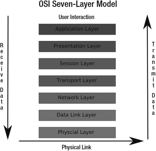
Figure 7-12. The OSI layer model
Note
We are going to describe the first three layers; for further information on the OSI model and layers, please see: http://www.webopedia.com/quick_ref/OSI_Layers.asp .
Layer 1 is concerned with how data is transmitted over the physical wire, and this is represented by the physical layer appearing at the bottom of Figure 7-12. When diagnosing network problems, it never hurts to jiggle the cables connecting your computer and the rest of the network. Also, when all else fails, you can try replacing cables. If cables are faulty, you will probably not see any lights on the switch/hub your host is connected to and the network card. Without these lights, your host will not be able to communicate to other hosts, so first try to replace the cable, and then the port it is connected to on the switch, and finally the network card .
Layer 2, the data link layer, provides the actual communication protocols across the wire. Problems encountered on this layer are rare. It is here that IP addresses get matched to MAC addresses by the use of ARP (Address Resolution Protocol). When two hosts on the network have the same IP address and a different MAC address, your host might start trying to send data to the wrong host. In this case, the ARP table may need to be flushed, and the host with the incorrect IP address will need to be taken offline.
Layer 3 is the network layer. It is able to discover the routes to your destination and send your data, checking for errors as it does so. This is the IP layer, so it can also be responsible for IPsec tunnelling. It is also this layer that is responsible for responding to your pings and other routing requests.
Layers 4 to 7 are described as the host layers. TCP operates in layers 4-5, the network and the session layers. The network layer is concerned with addressing and link reliability, things like error control and flow control. The session layer controls the establishing and closing out connections between computers. Layers 6 to 7 are responsible for connecting the user and this is where the HTTP and browser connects you to the web server .
General Network Troubleshooting
Things can go wrong on your network. Sometimes you aren’t able to connect to services, or some part of your network is incorrectly configured. To identify and resolve these problems, you will need a set of tools. We will examine a variety of tools:
ping: A command that sends packets between hosts to confirm connectivity
tcpdump: A command that displays and captures network traffic
mtr: A network diagnostic tool
nc: The netcat, another network diagnostic and testing tool
Ping !
Probably the most common tool that people use for checking their network is a command called ping. You can ping a host or an interface to see if it responds. In the output response from issuing the ping command, you are shown the time it has taken for that response to come back. You can ping the other side of the world and receive a response in milliseconds. That is good. If you get response times in the order of whole seconds or a “host unreachable” message, that is bad. Of course, if the host you’re pinging is on another continent or connected via a satellite link, ping times will be higher than if the host is sitting under your desk.
We just used the ping command to test our routes as follows:
$ ping 192.168.0.50PING 192.168.0.50 (192.168.0.50) 56(84) bytes of data.64 bytes from 192.168.0.50: icmp_seq=1 ttl=64 time=1.24 ms
The ping command can take the following arguments. For other arguments, refer to the man page.
ping –c <count> –i <interval> –I <interface address> –s <packet size> destination The ping command will send pings to a host indefinitely unless you either stop it, using Ctrl+C usually, or give it the number of pings to attempt using the –c number option.
You can also express the interval between pings as –i number (in seconds) and choose the interface you wish to use as the source address, specified by -I IP address or the interface name like: -I enp0s8. This is very handy if you have multiple interfaces and wish to test one of those. If you don’t define an address, it will normally ping using the primary interface on the host, usually eth0. You can also specify the packet size, using -s number of bytes, which is useful for testing bandwidth problems or problems with MTU settings.
Note
As mentioned earlier in the chapter, MTU is the maximum transmission unit. It is used to limit the size of the packets to what the network devices on that network can handle. Normally it is set to 1,500 bytes, but with jumbo frames it can be up to 9,000 bytes. Having larger-sized packets should mean that you can send more data more efficiently due to less packets traveling over the wire.
One of the first things you can do to test your network is to use ping to ping the interfaces you have configured. If they respond to pings from your own host, they are up and your interface is responding to TCP traffic. You can do this as follows:
ping 192.168.0.253PING 192.168.0.253 (192.168.0.253) 56(84) bytes of data.64 bytes from 192.168.0.253: icmp_seq=2 ttl=128 time=1.68 ms
Here we have sent a ping to the local IP address of our host, and we can see a series of responses indicating that a connection has been made and the time it took. If we had received no responses, we would know something is wrong with our interface or network .
The next step is to ping another host on your network, like your default gateway or your DNS server (these two hosts are critical for your Internet communications).
ping 192.168.0.1PING 192.168.0.1 (192.168.0.1) 56(84) bytes of data.64 bytes from 192.168.0.1: icmp_seq=1 ttl=128 time=2.97 ms
If you can get there, you know that your host can reach other hosts. You would then ping a host outside your network, say www.ibm.com or www.google.com , and test its response:
ping www.google.comPING www.l.google.com (150.101.98.222) 56(84) bytes of data.64 bytes from g222.internode.on.net (150.101.98.222): icmp_seq=1 ttl=59 time=20.0 ms
When you experience problems connecting to hosts on the Internet, it can be for many reasons. There are instances in which part of the Internet will go down because a core router is broken. In this situation, all your private network pings will return, but some pings to hosts on the Internet may not. If you don’t get a response from one host on the Internet, try another to see if the issue is local or somewhere else down the line. Some remote networks will actively block ICMP (Internet Control Message Protocol) traffic. These hosts will not respond to pings, and so you should check the response of other hosts before you panic. It is also handy in these situations to combine your investigations with other tools, one of which is mtr.
MTR
If you can ping hosts inside your network but can’t ping hosts outside your network, you can use a tool like traceroute or mtr for troubleshooting. Both provide a similar service: they trace the route they use to get to the destination host. Both also use “TTL expired in transit” messages to record those hosts along the way. What do these messages mean? Well, as we have already explained, TTL is used to kill TCP/IP packets so they don’t keep zinging around the Internet forever like some lost particle in the Large Hadron Collider. These commands take advantage of polite routers that send back “TTL expired in transit” messages when they kill your packet.
Let’s take a look at an example. If we do a ping to www.ibm.com and set the TTL to 1, it gets to the first router along the path to whatever www.ibm.com resolves to. That first router looks at the TTL and sees that it is 1. It now drops the packet and sends the expired‑in‑transit message.
ping -t 1 -c 1 www.ibm.comPING www.ibm.com.cs186.net (129.42.60.216) 56(84) bytes of data.From 192.168.0.254 (192.168.0.254) icmp_seq=1 Time to live exceeded--- www.ibm.com.cs186.net ping statistics ---1 packets transmitted, 0 received, +1 errors, 100% packet loss, time 0ms
The mtr and traceroute applications use the packet sent back to discover the IP address of the router (as the TCP/IP packet containing the reply will hold this information). It then displays that information and sends the next ping, this time with the TTL set to 2. Once the ping reaches our destination, we should receive the standard echo response. Some routers are configured not to send these ICMP messages and appear as blanks in the trace output.
Have a look at the output from mtr. Here we have used mtr to trace the route between the host au-mel-centos-1 and www.ibm.com using the following command:
sudo /usr/sbin/mtr www.ibm.com --reportStart: Tue May 17 18:04:01 2016HOST: au-mel-centos-1 Loss% Snt Last Avg Best Wrst StDev1.|-- 192.168.0.254 0.0% 10 2.7 2.4 1.8 3.2 0.02.|-- lnx20.mel4.something.net 0.0% 10 444.7 339.7 231.5 514.1 101.83.|-- xe-0-3-2.cr1.mel4.z.net 0.0% 10 456.4 332.2 211.5 475.6 103.04.|-- ae0.cr1.mel8.boo.net 0.0% 10 463.3 338.3 240.2 463.3 91.15.|-- ??? 100% 10 0.0 0.0 0.0 0.0 0.06.|-- a104-97-227-232.deploy.st 0.0% 10 476.3 341.9 229.3 476.3 97.0
Because we have used the --report switch the output isn’t shown until at least ten packets are sent. What the output from this command shows is that our first hop (each host/router we pass through is called a hop) is our firewall router. Next is the default gateway of our Internet connection at our ISP. As we pass through each hop along the way, we record information about our route. At the penultimate hop, we reach the IBM gateway. If you see a???, it will mean that the router has be set to deny returning ICMP packets, and mtr has printed ??? because it has not received the “TTL expired in transit” message. Some network administrators do this because they believe ICMP to be a security vulnerability.
For more information on some security vulnerabilities of ICMP, please read: http://resources.infosecinstitute.com/icmp-attacks/ .
The tcpdump Command
You can’t easily view communications at layer 1, but you can view them at layer 2 and layer 3 by using packet-sniffing software. One such application to view this detail is the tcpdump command‑line tool. The tcpdump command, and those like it, can view traffic at the packet level on the wire. You can see the packets coming in and out of your host. The tcpdump command, when run without any expressions, will print every packet crossing the interface. You can use expressions to narrow the array of packets types it will show. See the man tcpdump page for more information.
Note
Another program you can try is called Wireshark. It has a very good GUI that allows you to easily filter traffic. It also has a command-line utility called tshark, which operates in similar fashion to tcpdump. One of the good things about WireShark is that you can capture output from tcpdump (by specifying the –w option) and read it in WireShark, which does make viewing the information much easier. You can see more about Wireshark here: http://www.wireshark.org/ .
To show you how a network connection is established, we are going to make a connection from our firewall to our mail server. To illustrate what happens we are going to use the tcpdump command, the output appears as follows:
sudo /usr/sbin/tcpdump -i enp0s3tcpdump: verbose output suppressed, use -v or -vv for full protocol decodelistening on enp0s3, link-type EN10MB (Ethernet), capture size 96 bytes19:26:35.250934 ARP, Request who-has 192.168.0.1 tell 192.168.0.254, length 4619:26:35.475678 ARP, Reply 192.168.0.1 is-at 00:50:56:a9:54:44 (oui Unknown), length 2819:31:17.336554 IP 192.168.0.254.33348 > 192.168.0.1.smtp: Flags [S],seq 3194824921, win 29200, options [mss 1460,sackOK,TS val 47080429ecr 0,nop,wscale 7], length 019:31:17.619210 IP 192.168.0.1.smtp > 192.168.0.254.33348: Flags [S.],seq 2011016705, ack 3194824922, win 65535, options [mss 1460], length 019:31:17.619249 IP 192.168.0.254.33348 > 192.168.0.1.smtp: Flags [.],ack 1, win 29200, length 019:31:17.900048 IP 192.168.0.1.smtp > 192.168.0.254.33348: Flags [P.],seq 1:42, ack 1, win 65535, length 4119:31:17.900081 IP 192.168.0.254.33348 > 192.168.0.1.smtp: Flags [.],ack 42, win 29200, length 0
We have issued the command and told it to dump all the traffic that crosses the enp0s3 interface. We use the -i option to specify which interface to examine. In the output, we can break down the lines as follows:
timestamp source.port > destination.port : flags In the preceding output, the first two lines contain information telling you what the command is doing, in this case, listening on enp0s3. The rest are actual packets crossing the wire. The first numbers of each line, for example, 19:26:35.250934, are timestamps.
ARP, Request who-has 192.168.0.1 tell 192.168.0.254The first field (taking away the timestamp) is the protocol in the TCP/IP model. This is an ARP request, and ARP operates at the layer 2 (or data link layer) of the TCP/IP protocol stack. ARP is used to match up MAC addresses to IP addresses. You can see that 192.168.0.254 wants to know who has 192.168.0.1. There is an ARP reply that says that 192.168.0.1 is at MAC address 00:50:56:a9:54:44.
ARP, Reply 192.168.0.1 is-at 00:50:56:a9:54:44 Now that 192.168.0.254 knows where to send its packet, it tries to establish a socket by sending a SYN packet, Flags [S]. The SYN packet carries the SYN bit set and has an initial sequence number of seq 3194824921.
IP 192.168.0.254.33348 > 192.168.0.1.smtp: Flags [S], seq 3194824921,win 29200, options [mss 1460,sackOK,TS val 47080429 ecr 0,nop,wscale 7], length 0
The source and destination are described by 192.168.0.254 > 192.168.0.1.smtp, where .smtp is the port we are connecting to. That port maps to port 25. This is a connection being established to an SMTP mail server.
Let’s look at the next part: Flags [S]. The [S] after the source and the destination indicates that this is a SYN request and we are establishing a connection. Next is the initial sequence number of the packets, 3194824921. The sequence numbers are randomly generated and are used to order and match packets. This packet has a length of 0, that means that it is a zero‑byte packet (i.e., it contains no payload).
The other flags, win 29200, options [mss 1460,sackOK,TS val 47080429 ecr 0,nop,wscale 7], provide other information in the communication like sliding window size, maximum segment size, and so on.
Note
For more information, see http://www.tcpipguide.com/free/ t_TCPMaximumSegmentSizeMSSandRelationshiptoIPDatagra.htm.
The next packet is the reply from 192.168.0.1.
IP 192.168.0.1.smtp > 192.168.0.254.33348: Flags [S.], seq 2011016705,ack 3194824922, win 65535, options [mss 1460], length 0
This packet has the Flag [S.]set and a sequence number, 2011016705. The [S.] is an SYN ACK (or no flag to be precise)—this is a response to a SYN packet. The sequence number is another randomly generated number, and the data payload is again zero, (length 0). Attached to this sequence is an ACK response, ack 3194824922. This is the original initial sequence number incremented by 1, indicating that it is acknowledging our first sequence.
The next packet is another acknowledgment packet sent by the originating host:
IP 192.168.0.254.33348 > 192.168.0.1.smtp: Flags [.],ack 1, win 29200, length 0
In this output, the dot (.) means that no flags were set. The ack 1 indicates that this is an acknowledgment packet and that from now on, tcpdump will show the difference between the current sequence and initial sequence. This is the last communication needed to establish a connection between two hosts and is called the three-way handshake.
The last two packets are the exchange of data.
IP 192.168.0.1.smtp > 192.168.0.254.33348: Flags [P.],seq 1:42, ack 1, win 65535, length 41
The mail server is sending a message to the client on 192.168.0.254, as indicated by [P.] seq 1:42, ack 1. This is pushing, [P.], 41 bytes of data in the payload and is acknowledging the previous communication (ack 1).
IP 192.168.0.254.33348 > 192.168.0.1.smtp: Flags [.],ack 42, win 29200, length 0
The last communication is 192.168.0.254 acknowledging that packet, ack 42.
So now that you know how to see the communications between two hosts at the most basic level using packet‑sniffing programs such as tcpdump, let’s take a look at another useful tool, netcat.
Note
If you are interested in a deeper discussion of tcpdump and connection establishment, try the following article: http://www.linuxjournal.com/article/6447 .
The Netcat Tool
The other very useful tool you can use to diagnose network problems is the nc, or ncat, command. You can use this tool to test your ability to reach not only other hosts but also the ports on which they could be listening.
This tool is especially handy when you want to test a connection to a port through a firewall. Let’s test whether our firewall is allowing us to connect to port 80 on host 192.168.0.1 from host 192.168.0.254.
First, on host 192.168.0.1, we will make sure we have stopped our web server. For example, we issue the following command:
sudo systemctl stop httpdWe will then start the nc command using the -l, or listen, option on the host with the IP address of 192.168.0.1.
sudo nc -l 80This binds our nc command to all interfaces on the port. We can test that by running another command called netstat:
sudo netstat –lpttcp 0 0 *:http *:* LISTEN 18618/nc .
We launched the netstat command with three options. The –l option tells the netstat command to list listening sockets. The –p option tells netstat to display what applications are using each connection, and the last option, –t, tells netstat to look for TCP connections only.
The netstat command displays the programs listening on certain ports on your host. We can see in the preceding output that the program nc, PID of 18618, is listening for TCP connections on port 80. The *:http indicates that it is listening on all available addresses (network interface IP addresses) on port 80 (the :http port maps to port 80). OK, so we know our nc command is listening and waiting for connections. Next, we test our ability to connect from the host with the IP address of 192.168.0.254.
We will use the nc command to make a connection to port 80 on host 192.168.0.1 as in the following example:
nc 192.168.0.1 80hello host
The nc program allows us to test the connection between two hosts and send text to the remote host. When we type text and press Enter in our connection window, we will see what we have typed being echoed on the au-mel-centos-1 host.
sudo nc -l 80hello host
We now know our host can connect to the au-mel-centos-1 host on port 80, confirming that our firewall rules are working (or too liberal as the case may be if we were trying to block port 80).
You Dig It?
digis another handy tool for resolving DNS issues. If you use this tool in combination with others like ping and nc, you will be able to solve many problems. The dig command, short for domain information groper, is used to query DNS servers. Employed simply, the command will resolve a fully qualified domain name by querying the nameserver it finds in the /etc/resolv.conf file.
The /etc/resolv.conf file is used to store the nameserver information so your host knows which DNS server to query for domain name resolution. A /etc/resolv.conf file looks as follows:
sudo cat /etc/resolv.conf; generated by /sbin/dhclient-scriptsearch example.comnameserver 192.168.0.1nameserver 192.168.0.254
First you can see that the resolv.conf file was generated by the DHCP client. In general, this file should not need to be edited; often it will be overwritten by the NetworkManager. The default search domain is example.com, and any hostname searches will have that domain appended to the end of the query. Next, we have the nameserver(s) we wish to query for our domain name resolution. These should be in IP address format. If the first nameserver is unavailable, the second will be used.
The dig command will query these nameservers unless otherwise instructed. Let’s look at this query.
dig www.google.com; <<>> DiG 9.10.3-P4-Ubuntu <<>> www.google.com;; global options: +cmd;; Got answer:;; ->>HEADER<<- opcode: QUERY, status: NOERROR, id: 16714;; flags: qr rd ra; QUERY: 1, ANSWER: 12, AUTHORITY: 4, ADDITIONAL: 5;; OPT PSEUDOSECTION:; EDNS: version: 0, flags:; udp: 4096;; QUESTION SECTION:;www.google.com. IN A;; ANSWER SECTION:www.google.com. 233 IN A 150.101.161.181www.google.com. 233 IN A 150.101.161.187www.google.com. 233 IN A 150.101.161.146www.google.com. 233 IN A 150.101.161.152www.google.com. 233 IN A 150.101.161.153www.google.com. 233 IN A 150.101.161.159www.google.com. 233 IN A 150.101.161.160www.google.com. 233 IN A 150.101.161.166www.google.com. 233 IN A 150.101.161.167www.google.com. 233 IN A 150.101.161.173www.google.com. 233 IN A 150.101.161.174www.google.com. 233 IN A 150.101.161.180;; AUTHORITY SECTION:google.com. 10960 IN NS ns4.google.com.google.com. 10960 IN NS ns2.google.com.google.com. 10960 IN NS ns1.google.com.google.com. 10960 IN NS ns3.google.com.;; ADDITIONAL SECTION:ns1.google.com. 9192 IN A 216.239.32.10ns2.google.com. 13861 IN A 216.239.34.10ns3.google.com. 9192 IN A 216.239.36.10ns4.google.com. 2915 IN A 216.239.38.10;; Query time: 28 msec;; SERVER: 192.168.0.254#53(192.168.0.254);; WHEN: Sun Jul 17 15:43:41 AEST 2016;; MSG SIZE rcvd: 371
In the ANSWER SECTION, you can see the www.google.com hostname will resolve to twelve possible IP addresses. The AUTHORITY SECTION tells us which nameservers are responsible for providing the DNS information for www.google.com. The ADDITIONAL SECTION tells us what IP addresses the nameservers in the AUTHORITY SECTION will resolve to.
IN A indicates an Internet address (or relative record). IN NS indicates a nameserver record. Numbers such as 233, 10960, and 9192, shown in the three sections in the preceding code, indicate how long in seconds the record is cached for. When they reach zero, the nameserver will query the authoritative DNS server to see whether it has changed.
At the bottom of the dig output, you can see the SERVER that provided the response, 192.168.0.254, and how long the query took, 28 msec.
You can use dig to query a particular nameserver by using the @ sign, here we are using one of the Google public DNS servers. You can also query certain record types by using the –t type option. For example, if we wanted to test our DNS server was working properly, we could use dig to find the IP address of Google’s mail server.
dig @8.8.8.8 –t MX google.com<snip>;; QUESTION SECTION:;google.com. IN MX;; ANSWER SECTION:google.com. 392 IN MX 20 alt1.aspmx.l.google.com.<snip>google.com. 392 IN MX 10 aspmx.l.google.com.;; AUTHORITY SECTION:google.com. 10736 IN NS ns4.google.com.google.com. 10736 IN NS ns3.google.com.google.com. 10736 IN NS ns1.google.com.google.com. 10736 IN NS ns2.google.com.;; ADDITIONAL SECTION:aspmx.l.google.com. 55 IN A 64.233.189.27aspmx.l.google.com. 112 IN AAAA 2404:6800:4008:c03::1b<snip>ns3.google.com. 8968 IN A 216.239.36.10ns4.google.com. 2691 IN A 216.239.38.10<snip>
We could use this information and compare the response from other nameservers. If our nameserver has provided the same information, our DNS server is working correctly. If there is a difference or we return no results, we would have to investigate our DNS settings further. In Chapter 9, we discuss DNS and the dig command in more detail.
Other Troubleshooting Tools
The programs we have just discussed cover basic network troubleshooting. Many other networking tools are available to further help diagnose problems. We briefly touched on the netstat command, but there are a multitude of others. Table 7-4 lists some of the most common troubleshooting commands and their descriptions.
Table 7-4. Other Handy Network Diagnostic Tools
Tool | Description |
|---|---|
netstat | This tool gives the status of what is listening on your host plus much more, including routes and statistics. |
host | Another tool to diagnose DNS servers. We will show you how to use host in Chapter 9. |
openssl s_client | This is useful to test SSL connections as it can try to establish an SSL connection to a port on a remote host. |
arp | This program queries and manages the ARP cache table, and allows you to delete ARP entries. |
The list of useful tools in Table 7-4 is by no means exhaustive. However, armed with only a few of these tools, you can diagnose many common problems.
Adding Routes and Forwarding Packets
The other common thing you will do with the ip command is add routes to your host. Routes are the pathways your host should follow to access other networks or other hosts.
We want to show you an example of how to add a route using the ip command. First, we will explain what we want to achieve. We are going to route traffic from one network to another via our firewall. We are on our main server host, which has the IP address 192.168.0.1—Host A in Figure 7-13. We have our firewall/router sitting on our network with the IP address 192.168.0.254 on interface enp0s8—Host B. We have configured interface enp0s9 on our firewall host with the address 192.168.1.254/24. The network 192.168.1.0/24 is going to be our wireless network, which we will separate into its own subnet. There is a host with which we wish to communicate on that network with the IP address 192.168.1.220—Host C. Figure 7-13 provides a diagram of our network.
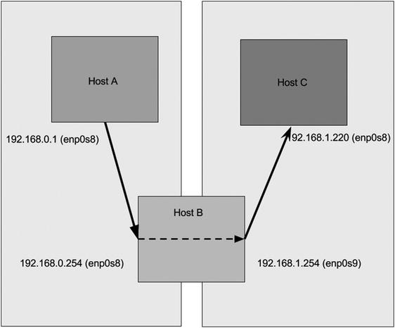
Figure 7-13. Adding a route
Host A and Host C are properly configured to route between the networks. In their routing tables, they send all requests destined for other networks via their default gateway. In this case their default gateway is the firewall/router, and the address of their default gateway is 192.168.0.254 and 192.168.1.254, respectively. Host A does not know that Host B has the 192.168.1.0/24 network attached to its enp0s9 interface, nor does Host C know that Host B has the 192.168.0.0/24 network attached to its enp0s8 interface.
Note
We are going to use the ip command to explore our route tables. But first you need to know that there are different route tables. By default there is a main, local and default. You can also add your own. You can view the different tables by issuing ip route show table local|main|default|number. When we issue the ip route show command we are seeing the main table, the equivalent to ip route show table main.
Let’s view the route table for Host A. By issuing the following command, we can list the route table of Host A:
sudo /sbin/ip route show192.168.0.0/24 dev enp0s8 proto kernel scope link src 192.168.0.1default via 192.168.0.254 dev enp0s8 scope link
The route table shows us the networks that this host knows about. It knows about its own network, as shown with 192.168.0.0/24 dev enp0s8 proto kernel scope link src 192.168.0.1.
You can see the default route, default via 192.168.0.254 dev enp0s8 scope link. The default route points to the host on the network, which can handle the routing requests for hosts on its network. These are devices with usually more than one interface or IP address network attached to it and can therefore pass on the routing requests to hosts further along the routing path to the final destination.
Let’s compare that route table with the one for Host B. Host B is our network router, so it should have more than one network attached to its interfaces.
sudo /sbin/ip route show192.168.0.0/24 dev enp0s8 proto kernel scope link src 192.168.0.254192.168.1.0/24 dev enp0s9 proto kernel scope link src 192.168.1.25410.204.2.10 dev dsl-provider proto kernel scope link src 10.0.2.155default dev dsl-provider scope link
First let’s take a look at the default route on Host B. It indicates that anything it doesn’t know about it will send out of dev dsl-provider. The device dsl-provider is our PPP link to our ISP. The first line is related to that route. It shows us that the network 10.204.2.10 is reached via the device dsl-provider and through the link src address of 10.0.2.155. The 10.204.2.10 host is in our ISP and is assigned to us by our ISP when we make our PPP connection.
On Host C we have this route configuration:
sudo /sbin/ip route show192.168.1.0/24 dev enp0s8 proto kernel scope link src 192.168.0.220default via 192.168.1.254 dev enp0s8 scope link
We know that Host A and Host C are on different networks, and by themselves they cannot reach each other. For us to make a simple connection, like a ping connection, from Host A to Host C, the TCP/IP packets have to go through Host B. The ping command sends an ICMP echo request to the host specified on the command line. The echo request is a defined protocol that says to the requesting host what would in computer speak be “I’m here.”
Note
Internet Control Message Protocol (ICMP) is a TCP/IP protocol that is used to send messages between hosts, normally error messages; but in the case of ping, it can also send an informational echo reply.
So let’s see if we can reach Host C from Host A by issuing the ping command on Host A.
ping –c 4 192.168.1.220PING 192.168.1.220 (192.168.1.220) 56(84) bytes of data.64 bytes from 192.168.1.220: icmp_seq=1 ttl=64 time=1.79 ms
We have used the ping command, a way of sending network echoes, with the –c 4 option to limit the number of echo replies to 4. This is enough to confirm that we can reach our Host C from our Host A. That was relatively easy. Let’s look at a slightly different scenario in which we have to add our own route. You can see a diagram of it in Figure 7-14.
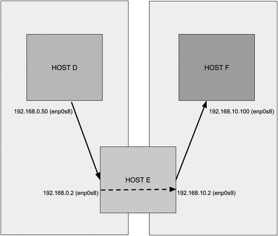
Figure 7-14. Adding another route
In this scenario, we will say that Host D is trying to reach Host F by passing through Host E. Host E has two Ethernet devices, enp0s8 and enp0s9. The device enp0s8 is attached to the 192.168.0.0/24 network with IP address 192.168.0.2, and enp0s9 is attached to the 192.168.10.0/24 network with IP address 192.168.10.2. Host D is on the 192.168.0.0/24 network with IP address 192.168.0.50. Host D has a default route of 192.168.0.254. Host F is on the 192.168.10.0/24 network with IP address 192.168.10.100. Host F has the default route 192.168.10.254.
Let’s look at their route tables:
Host D192.168.0.0/24 dev enp0s8 proto kernel scope link src 192.168.0.50default via 192.168.0.254 dev enp0s8 scope linkHost E192.168.0.0/24 dev enp0s8 proto kernel scope link src 192.168.0.2192.168.10.0/24 dev enp0s9 proto kernel scope link src 192.168.10.2default via 192.168.0.254 dev enp0s8 scope linkHost F192.168.10.0/24 dev enp0s8 proto kernel scope link src 192.168.10.100default via 192.168.10.254 dev enp0s8 scope link
You can see that Host E contains the two interfaces with the two different networks attached. To get Host D to see Host F, we need to tell Host D to get to Host F via Host E. We do that by adding a route like this:
sudo /sbin/ip route add 192.168.10.0/24 via 192.168.0.2 dev enp0s8Here we have to use the ip command combined with the route object to add a route to the 192.168.10.0/24 network from our Host D. We give the command the IP address of the host, 192.168.0.2, which is the router on our network for the destination network.
Now that Host D has the pathway to get to the 192.168.10.0/24 network, we should be able to ping Host F, right?
ping 192.168.10.100PING 192.168.10.100 (192.168.10.100) 56(84) bytes of data.
It appears packets are not being returned, we see no output from that command. What if we test this by trying to ping Host D from Host F. We use the –c 4 option to limit the number of pings that are sent to the destination host to four.
ping –c 4 192.168.0.50PING 192.168.0.50 (192.168.0.50) 56(84) bytes of data.--- 192.168.0.50 ping statistics ---4 packets transmitted, 0 received, 100% packet loss, time 2999ms
Our hosts can’t see each other when we ping from Host F to Host D. Why is that? It is because Host F knows nothing of the 192.168.0.0/24 network. This host will send anything it doesn’t know about to its default gateway. And because the default gateway of Host F isn't configured to know where to send packets to 192.168.0.50, it will send them off to its default gateway. Eventually these packets will die.
Note
Part of the TCP/IP protocol is a TTL—time to live—where after a period of time the packets are ignored and dropped by upstream routers. TTL is indicated by a number, usually 64 these days, but can be 32 or 128. As packets pass through each router (or hop), they decrease the TTL value by 1. If the TTL is 1 when it reaches a router and that router is not the final destination, the router will drop the packet and send a “TTL expired in transit” message using the ICMP protocol. You will see how useful this is shortly in the “MTR” section.
So how do we fix this? Well, we add a route to Host F telling it how to send packets to Host D via Host E.
sudo /sbin/ip route add 192.168.0.0/24 via 192.168.10.2 dev enp0s8Now when Host F tries to ping Host D, we get the following result:
ping 192.168.0.50PING 192.168.0.50 (192.168.0.50) 56(84) bytes of data.64 bytes from 192.168.0.50: icmp_seq=1 ttl=64 time=1.24 ms
After adding the route to Host F, we can now reach Host D. Combining all this information, we can use these commands in a script to bring up an interface, add an IP address, and add a route.
#!/bin/bash# bring up the interfaceip link set enp0s8 up# add an addressip addr add 192.168.10.1/24 dev enp0s8# add a routeip route add 192.168.100.1 via 192.168.10.254 dev enp0s8# ping the hostping 192.168.100.1 –c 4# bring down the route, remove the address and bring down the interface.ip route del 192.168.100.1 via 192.168.10.254 dev enp0s8ip addr del 192.168.10.1/24 dev enp0s8ip link set enp0s8 downexit 0
We have used the same command to control our interface, bringing it up, adding an address, and then adding a route. We then brought it down again with the same command. This sort of script can be used to copy files from one host to another host or make any sort of connection.
Let’s now move on to further explore how you can test your connections and troubleshoot your network using a few simple utilities.
Netfilter and iptables
Many people now understand what a firewall is, as they have started to become mandatory on even the simplest of hosts. You may already be familiar with a firewall running on your desktop. These simple firewalls can be used to block unwanted traffic in and out of a single host, but that is all they can do.
Netfilter is a complex firewall application that can sit on the perimeter of a network or on a single host. Not only can it block unwanted traffic and route packets around the network, but it can also shape traffic. “Shape traffic?” you may be wondering, “What’s that?”
Packet shaping is the ability to alter packets passing in and out of your network. You can use it to increase or decrease bandwidth for certain connections, optimize the sending of other packets, or guarantee performance of specific types of packets. This can be beneficial to companies that want to ensure VoIP calls are not interrupted by someone downloading GoT.
How Netfilter /iptables Work
The iptables command is the user‑space management tool for Netfilter. Netfilter was pioneered by Paul “Rusty” Russell and has been in the Linux kernel since version 2.4. It allows the operating system to perform packet filtering and shaping at a kernel level, and this allows it to be under fewer restrictions than user‑space programs. This is especially useful for dedicated firewall and router hosts as it increases performance significantly.
Note
The term user-space program refers to a tool used by end users to configure some portion of the operating system. In this case the internal operating system component is called Netfilter, and the user-space component, the command you use to configure Netfilter, is called iptables.
Packet filtering and shaping is the ability to change or discard packets as they enter or leave a host according to set of criteria, or rules. Netfilter does this by rewriting the packet headers as they enter, pass through, and/or leave the host.
Netfilter is a stateful packet‑filtering firewall. Two types of packet‑filtering firewalls exist: stateful and stateless. A stateless packet‑filtering firewall examines only the header of a packet for filtering information. It sees each packet in isolation and thus has no way to determine whether a packet is part of an existing connection or an isolated malicious packet. A stateful firewall maintains information about the status of the connections passing through it. This allows the firewall to filter packets based on the state of the connection, which offers considerably finer‑grained control over your traffic.
Netfilter is part of the Linux kernel and can be controlled and configured in the user space by the iptables command.. In this chapter, we will frequently use iptables to refer to the firewall technology in general. Most Linux‑based distributions will have an iptables package, but they may also have their own tool for configuring the rules Firewall-cmd and ufw.
Netfilter works by referring to a set of tables. These tables contain chains, which in turn contain individual rules. Chains hold groups of ordered and alike rules; for example, a group of rules governing incoming traffic could be held in a chain. Rules are the basic Netfilter configuration items that contain criteria to match particular traffic and perform an action on the matched traffic.
Traffic that is currently being processed by the host is compared against these rules, and if the current packet being processed satisfies the selection criteria of a rule, the action, known as a target, specified by that rule is carried out. These actions, among others, can be to ignore the packet, accept the packet, reject the packet, or pass the packet on to other rules for more refined processing. Let’s look at an example; say the Ethernet interface on your web server has just received a packet from the Internet. This packet is checked against your rules and compared to their selection criteria. The selection criteria could include such items as the destination IP address and the destination port. In this example, say you want incoming web traffic on your network interface to be allowed access to the HTTP port 80 of your listening web service. If the incoming traffic matches these criteria, you specify an action to let it through.
Each iptables rule relies on specifying a set of network parameters as selection criteria to select the packets and traffic for each rule. You can use a number of network parameters to build each iptables rule. For example, a network connection between two hosts is referred to as a socket. This is the combination of a source IP address, source port, destination IP address, and destination port. All four of these parameters must exist for the connection to be established, and iptables can use these values to filter traffic coming in and out of hosts. Additionally, if you look at how communication is performed on a TCP/IP‑based network , you will see that three protocols are used most frequently: Internet Control Message Protocol (ICMP) , Transmission Control Protocol (TCP) , and User Datagram Protocol (UDP) . The iptables firewall can easily distinguish between these different types of protocols and others.
With just these five parameters (the source and destination IP addresses, the source and destination ports, and the protocol type), you can now start building some useful filtering rules. But before you start building these rules, you need to understand how iptables rules are structured and interact. And to gain this understanding, you need to understand further some of the initial iptables concepts such as tables, chains, and policies, which we will discuss next, along with touching a little on network address translation (NAT).
Tables
We talked about Netfilter having tables of rules that traffic can be compared against, possibly resulting in some action taken. Netfilter has four built‑in tables that can hold rules for processing traffic. The first is the filter table, which is the default table used for all rules related to the filtering of your traffic. The second is nat, which handles NAT rules. Next is the mangle table, which covers a variety of packet alteration functions. There is the raw table, which is used to exempt packets from connection tracking and is called before any other Netfilter table. And lastly there is the security table which are used for Mandatory Access Control (MAC) network rules and is processed after the filter table. This is used by modules like SELinux .
Chains
Each of the Netfilter tables, filter, nat, mangle, raw and security, contain sets of predefined hooks that Netfilter will process in order. These hooks contain sequenced groupings of rules called chains. Each table contains default chains that are built into the table. The built‑in chains are described in Table 7-5.
Table 7-5. Built-in Chains
Chain | Description |
|---|---|
INPUT | Used to sequence rules for packets coming to the host interface(s). Found in the filter, mangle and security tables only. |
FORWARD | Used to sequence rules for packets destined for another host. Found in the filter, mangle and security table only. |
OUTPUT | Used to sequence rules for outgoing packets originating from the host interface(s). Found in the filter, nat, mangle, raw and security tables. |
PREROUTING | Used to alter packets before they are routed to the other chains. Found in the nat, mangle, and raw tables. |
POSTROUTING | Used to alter packets after they have left the other chains and are about to go out of the interface(s). Found in the nat and mangle tables only. |
Each chain correlates to the basic paths that packets can take through a host. When the Netfilter logic encounters a packet, the first evaluation it makes is to which chain the packet is destined. Not all tables contain all the built‑in chains listed in Table 7-5.
Let’s look at the filter table for example. It contains only the INPUT, OUTPUT, and FORWARD chains and it is the one you configure most often. If a packet is coming into the host through a network interface, it needs to be evaluated by the rules in the INPUT chain. If the packet is generated by this host and going out onto the network via a network interface, it needs to be evaluated by the rules in the OUTPUT chain. The FORWARD chain is used for packets that have reached the local network interface but are destined for some other host (for example, on hosts that act as routers). You are able to create chains of your own in each table to hold additional rules. You can also direct the flow of packets from a built‑in chain to a chain you have created, but this is only possible within the same tablespace .
Let us now explore the life of a packet as it comes into your system. We will be concerning ourselves with the filter table solely, as this is the table you will deal with most often. Remember that the table filter contains the three built‑in chains: INPUT, FORWARD, and OUTPUT. These all have the default policy of ACCEPT (we talk about policies shortly). Looking at Figure 7-15, which shows how a normal network packet would flow through the filter table.
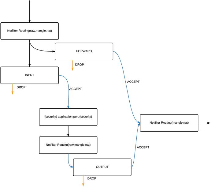
Figure 7-15. Traffic flow through the filter table
In Figure 7-15, you can see the way that packets will flow through the filter table. The Netfilter firewall program will route incoming IP packets to either the INPUT or the FORWARD chain depending on their destination address. It makes this decision in the Netfilter routing block and packets are inspected by raw, mange and nat tables before reaching filter.
If the incoming packets are destined for another host, and IP forwarding has been enabled on the firewall host, they are delivered to the FORWARD chain. Once dealt with by any rule set in that chain, the packets will leave the host if they are allowed or be dropped (DROP) if they are not. Like in the OUTPUT chain, these packets are routed by the Netfilter program and passed on to other tables (mangle, nat) before they leave on the wire.
If the packets are destined for the firewall host itself, they will be passed to the INPUT chain and if they are accepted by any rule sets in that chain will be passed to the application (via the security table). The application may then wish to send a response back. If so it, this traffic is managed by the OUTPUT chain.
The OUPUT chain is for packets originating on the actual firewall host destined for another host elsewhere. These can be new connections being initiated from the firewall to remote sockets or it can be part of an established packet flow .
Tip
Think of the hooks in the preceding explanation as a set of fishing hooks with different types of bait to catch different types of fish. When a specific type of fish is swimming by it is attracted to a certain bait. Once it is hooked we determine its fate by what is at the end of the line. iptables is just like fishing for network packets!
Policies
Each built-in chain defined in the filter table can also have a policy. A policy is the default action a chain takes on a packet to determine whether a packet makes it all the way through the rules in a chain without matching any of them. The policies you can use for packets are DROP, REJECT, and ACCEPT. By default both Ubuntu and CentOS have ACCEPT as the default policy for all chains in all tables.
The DROP policy discards a packet without notifying the sender, often described as ‘dropping to the floor’. The REJECT policy also discards the packet, but it sends an ICMP packet to the sender to tell it the rejection has occurred. The REJECT policy means that a device will know that its packets are not getting to their destination and will report the error quickly instead of waiting to be timed out, as is the case with the DROP policy. The DROP policy is contrary to TCP RFCs (Requests for Comment) and can be a little harsh on network devices; specifically, they can sit waiting for a response from their dropped packet(s) for a long time. But for security purposes, it is generally considered better to use the DROP policy rather than the REJECT policy, as it provides less information about your network to the outside world.
The ACCEPT policy accepts the traffic and allows it to pass through the firewall if it is not caught by a rule in the chain. Naturally, from a security perspective, this renders your firewall ineffective if it is used as the default policy. As we have said, by default, iptables configures all chains with a policy of ACCEPT, and it is best practice to set this to a policy of DROP for all chains is recommended – but only after careful consideration as this can stop all network traffic if done incorrectly.
Caution
On remote hosts it is very easy to isolate the host from the network you are using to configure it. Make sure you have configured ACCEPT rules that allow you to connect before changing the policy to DROP.
The default policy of DROP falls in line with the basic doctrine of a ‘default stance of denial’ for the firewall. You should deny all traffic by default and open the host only to the traffic to which you have explicitly granted access. This denial can be problematic, because setting a default policy of DROP for the INPUT and OUTPUT chains means incoming and outgoing traffic are not allowed unless you explicitly add rules to allow traffic to come into and out of the firewalled host. Again some care and consideration is required when doing this as it will cause all services and tools that connect from your host or from your internal network via this firewall to fail if they are not explicitly allowed to enter or leave .
Network Address Translation
Network address translation allows your private network IP address space to appear to originate from a single public IP address. It does this with the help of IP masquerade, which rewrites IP packet headers. NAT holds information about connections traversing the firewall/router in translation tables. Generally speaking, an entry is written into the translation table when a packet traverses the firewall/router from the private to the public address space. When the matching packet returns, the router uses the translation table to match the returning packet to the originating source IP.
Many years ago, each host on the Internet was given a public IP address to become part of the Internet and talk to other hosts. It was soon realized that the available addresses would run out if every host that wanted to be on the Internet was given its own public IP address. NAT was invented to be able to have a private address space appear to come from a single IP address.
Using the Firewall-cmd Command
With CentOS, as we have mentioned, Firewalld is installed by default. Firewalld comes with two configuration tools, one is the GUI firewall-config and the other is the firewall-cmd command line tool. We are going to show you how to use this command to manage your host.
Firstly some background onFirewalld . Firewalld has the familiar concept of zones. Zones are names given to various levels of trust in your network. Starting with the low trust drop zone and progressing to higher levels of trust with public, external, dmz, work, home, internal and trusted zones. The idea is that you add your interfaces to one of these zones depending on your security needs. By default interfaces are added to the public zone.
It also has the ability to define a service. A service can be defined in an xml formatted file with a simple syntax. Take the https.xml zone file in the /usr/lib/firewalld/services directory:
<?xml version="1.0" encoding="utf-8"?><service><short>Secure WWW (HTTPS)</short><description>HTTPS is a modified ..<snip>.. be useful.</description><port protocol="tcp" port="443"/></service>
You can create your own service files in the /etc/firewalld/services directory. These allow you reference them as service objects in your firewall configurations.
The configuration options for firewalld can be found in the /etc/firewalld/firewalld.conf and /etc/sysconfig/firewalld. In the /etc/firewalld/firewalld.conf you can set the default zone and other options. In the /etc/sysconfig/firewalld you can add any arguments to the the firewalld daemon.
By default the firewalld is not running on your system. You will need to enable it to make use of it. You can run stop|start|disable|enable|status on the firewalld service with the following commands:
sudo systemctl stop|start|disable|enable|status firewalldYou can check it’s running state with:
sudo firewall-cmd –statenot running
To start firewalld, and make sure it starts again when you reboot the host, you need use systemctl to enable and then start the firewalld service. Once it is started we can view which zones we have active:
sudo firewall-cmd --get-active-zonespublicinterfaces: enp0s8 enp0s9
To get information about a zone, you can execute the following:
sudo firewall-cmd --zone=public --list–allpublic (default, active)interfaces: enp0s8 enp0s9sources:services: dhcpv6-client sshports:masquerade: noforward-ports:icmp-blocks:rich rules:
Here we can see that the public zone is the default and that it is active. We can also see the interfaces that have been attached to it. The services describe what services are allowed access, the DHCP client and SSH. DHCP allows us to get an IP address automatically for our interface. These are defined in the services xml files and we can also use ports if you need to.
If you want to permanently change the zone for an interface you can modify the network interface with nmcli:
sudo nmcli c modify enp0s9 connection.zone dmzThis will add the ‘ZONE=dmz’ to the interface profile file /etc/sysconfig/network-scripts/ifcfg-enp0s9. This will not take any effect until we bring that interface up again.
We can add a http service to the zone labelled dmz. We do that with the following:
sudo firewall-cmd --zone=dmz --add-service=https --permanentIf we are going to make a change permanent we need to remember to add the --permanent option. You can reload the configuration without losing state information (does not interrupt connections) and you can reload that does lose state (people lose connections) with the complete reload:
sudo firewall-cmd reloadsudo firewall-cmd --complete-reload
Here you can see that our dmz now has the https and ssh services attached to it:
sudo firewall-cmd --zone=dmz --list-alldmzinterfaces:sources:services: https sshports:masquerade: noforward-ports:icmp-blocks:rich rules:
But you can see that it has no interfaces. We are going to add enp0s9 to this interface and like we said, the interface needs to ‘upped’ again.
sudo nmcli c up enp0s9You should now be able to reach the HTTPS web service running on the enp0s9 interface.
Using the ufw Command
Ubuntu also has a tool for manipulating firewall rules from the command line. It is called ufw and is available from the ufw package.
Tip
We will talk more about installing packages in Chapter 8.
ufw is completely different to Firewalld. Under the covers it uses straight iptables directives to create firewall rules. If we look at the rule files in the /etc/ufw/ directory we can see the instructions that ufw uses to create the Netfilter rulesets.
Let’s now show some of the basic commands.
You enable or disable ufw like so:
sudo ufw enable|disableTo get an output of current firewall status:
sudo ufw status numberedStatus: activeTo Action From-- ------ ----[ 1] 22/tcp ALLOW IN Anywhere[ 2] 22/tcp (v6) ALLOW IN Anywhere (v6)
This is saying we are going to allow traffic coming in (ALLOW IN), that originates from any network (Anywhere), and, that is destined for port TCP 22 (on both IPv4 and IPv6 interfaces).
You can add another rule like the following to allow http traffic to any local interface:
sudo ufw allow 80/tcpRule addedRule added (v6)sudo ufw status numbered...[ 3] 80 ALLOW IN Anywhere[ 4] 80 (v6) ALLOW IN Anywhere (v6)...
In the above you can see that we have added access to port 80 from anywhere on all IPv4 and IPv6 interfaces. That can be expressed like this too for common services (that is, services listed in the /etc/services file).
sudo ufw allow httpTo remove a rule you can use the delete command:
sudo ufw delete 3Deleting:allow 80Proceed with operation (y|n)? yRule deleted
We need to answer either a y or n at the prompt to confirm if we wish to delete the rule. You can also specify the rule you wish to delete this:
sudo ufw delete allow httpYou can also use a simplified syntax to describe rules you might need for applications. You can see the way ufw allows TCP port 22 access to the system (remembering that TCP port 22 is used for OpenSSH). The file /etc/ufw/applications.d/openssh-server is used to configure port 22 access by default.
[OpenSSH]title=Secure shell server, an rshd replacementdescription=OpenSSH is a free implementation of the Secure Shell protocol.ports=22/tcp
Here we have the namespace [OpenSSH], followed by the title and description. The ports we need are then described, with multiple ports and protocols being separated by a ‘|’. For example, let’s say we have a web application that requires the following TCP ports open, 80, 443 and 8080. We can create a ufw application by adding the file /etc/ufw/applications.d/web-server with the following:
[WebServer]title=Application Web Serverdescription=Application X web servicesports=80/tcp|443/tcp|8080/tcp
To view our new configuration we can use the following command:
sudo ufw app info WebServersudo: unable to resolve host ubuntu-xenialProfile: WebServerTitle: Application Web ServerDescription: Application X web servicesPorts:80/tcp443/tcp8080/tcp
After creating an application configuration we need issue the update subcommand like this:
sudo ufw app update WebServer Then to apply the new ruleset you can issue something like this to allow only hosts in the 192.168.0.0/24 address range.
sudo ufw allow from 192.168.0.0/24 to any app WebServerRule added
Let’s break this down a little. We are saying that we want to allow any connection originating from the 192.168.0.0/24 network to any address on our localhost to any port that is listed in the app WebServer. To now list what we have done we will see the following:
sudo ufw allow from 192.168.0.0/24 to any app WebServersudo ufw status numberedStatus: activeTo Action From-- ------ ----[ 1] WebServer ALLOW IN 192.168.0.0/24
Traffic traversing this host needs to be routed with the ufw route command. For example, we have SSH traffic coming in on enp0s8 and leaving on enp0s9, we would write the ufw routing rule like this:
sudo ufw route allow in on enp0s8 out on enp0s9 to any port 22 proto tcpHere we are saying allow SSH traffic (22) coming in on enp0s8 and out on enp0s9 to any destination IP address. This creates a rule in iptables that, when viewed with the iptables -L command looks like this:
Chain ufw-user-forward (1 references)num target prot opt source destination1 ACCEPT tcp -- 0.0.0.0/0 0.0.0.0/0 tcp dpt:22
Let’s move on to explore more about iptables and what this means.
Using the iptables Command
Previously we have described the concepts of packet flows in Netfilter and we have introduced the two main commands that we can use to manage them, firewall-cmd and ufw. It is important that we now understand how they work and what they do. We will now show you how to use the iptables command to manage Netfilter. The iptables command allows you to do the following:
List the contents of the packet filter rule set.
Add/remove/modify rules in the packet filter rule set.
List/zero per-rule counters of the packet filter rule set.
For IPv6 you use the ip6tables command, but syntactically it is the same command, but instructs Netfilter how to operate on IPv6 packets. In this section we are going to talk mostly about the IPv4 command but there is no difference in the commands usage for IPv6. To effectively use the iptables command, you must have root privileges. The basic iptables command structure and arguments are as follows:
iptables –t table-name command chain rulenumber paramaters –j targetTable 7-6 gives a rundown on the commands, shown in the preceding syntax command, we will be demonstrating and their description.
Table 7-6. Command Options Available to the iptables Command
Option | Description |
|---|---|
-L | Lists the current rules of iptables you have in memory. |
-D | Deletes a rule in a chain. The rule to delete can be expressed as a rule number or as a pattern to match. |
-I | Inserts a rule into a chain. This will insert the rule at the top of the chain unless a rule number is specified. |
-F | Flushes a chain. This will remove all the rules from a chain or all the rules in all the chains in a table if no chain is specified. |
-A | Appends a rule to a chain. Same as -I except the rule is appended to the bottom of the chain by default. |
-X | Deletes a chain. The chain must be empty and not referenced by any other chain at the time you wish to delete it. |
-N | Creates a new chain. There can be no target already existing with the same name. |
-R | Replace an existing rule |
-C | Check if the rules exists in a chain and returns an exit code. |
-S | Prints the rules (similar to –L) in the specified chain. These can be used to restore IPtables later on. |
-P | Sets a default policy for a chain. Each built‑in chain (INPUT, OUTPUT, FORWARD, POSTROUTING, etc.) has a default policy of either ACCEPT, REJECT, or DROP. |
Caution
It is always a good idea when you are working with firewall rules to have access to a system console in the event that you make a mistake and block all your network traffic. Changing your firewall rules over the network, especially on remotely housed systems, can leave you in an awkward position if you make a mistake (and everyone makes at least one mistake).
iptables –t table-name command chain rulenumber paramaters –j targetA large number of parameters, shown in the iptables command syntax as parameters above, can be used to manipulate packets as they pass through your firewall. When we explained chains, we said they were like hooks. The parameters are the different types of bait that sit on the hook. Each parameter will attract packets depending on the information in the packet. It can be the source and destination addresses of the packet or the protocol. The packet can furthermore be matched to source or destination ports or the state the packet is in. The parameters can also be used to match packets, capture them, tag them, and release them.
iptables –t table-name command chain rulenumber paramaters –j target The target argument, depicted by –j target in the iptables command syntax, is the action to be performed on the packet if it has been hooked. Common targets are ACCEPT, DROP, LOG, MASQUERADE, and CONNMARK. The target can also be another user‑defined chain.
We want to now show you how to use the iptables command by running you through some examples.
The iptables command is common to both Ubuntu and CentOS and operates in the same way. Let’s look at listing the contents of the iptables rule sets we currently have running. We do that by issuing the following command:
sudo /sbin/iptables -t filter -L --line-numbersHere we are viewing the filter table. The –L option lists all the chains and their associated rules with line numbering, specified by --line-numbers, for each. The line numbering is important because, as has been mentioned, iptables runs through each rule sequentially starting from the first to the last. When you want to add a new rule or delete an old rule, you can use these numbers to pinpoint which rule you want to target. Here is the listed output of that command in Listing 7-7.
Listing 7-7. iptablesfilter table
sudo /sbin/iptables -t filter -L --line-numbersChain INPUT (policy ACCEPT)num target prot opt source destinationChain FORWARD (policy ACCEPT)num target prot opt source destinationChain OUTPUT (policy ACCEPT)num target prot opt source destination
That is a little anti-climactic. We, by default, have no rules in any of our chains in the filter table. This of course means that any service that is started on our host can immediately begin communicating on our network. We should fix that.
It is up to you to set the minimal rule requirements and we will give help with these rules as we go along. We have the option here to create our own chain so that we can group our firewall rules. You don’t have to create a new chain, but you might if you want to keep all your rules separate from the default chains, our have them relate to logical business groups. We could also define the chain by the logical network group, we are going to keep it simple and call it IPV4-INCOMING.
sudo /sbin/iptables –t filter –N IPV4-INCOMINGThis command creates a new chain using –N IPV4-INCOMING in the filter table as denoted by –t filter. It does not have any rules associated with it yet, but by the end of this section you will be able to add and remove rules.
Note
You don’t have to use the preceding naming standard for naming your chains. However, you will benefit from using something that makes sense to your configuration. Otherwise, the output of your iptables rules could look very messy and hard to diagnose for faults. You also don’t need to create your own user-defined chains if you don’t want to, but it will make reading your rules simpler if you do.
By listing our iptables you will now see the new chain we have created:
Chain IPV4-INCOMING (0 references)num target prot opt source destination
It has no rules in it yet so we are going to create some. Let’s start with a simple rule..
sudo iptables -t filter -A IPV4-INCOMING -d 0.0.0.0/0 -s 0.0.0.0/0 -j ACCEPTChain IPV4-INCOMING (0 references)num target prot opt source destination1 ACCEPT all -- anywhere anywhere
This rule allows all connections from anywhere on any port and is the equivalent of the ACCEPT policy. Be we are just going to concentrate on explaining the command we have issued rather than its merits. Breaking it down we are again working on the filter table. Next we are adding (-A) a rule to the IPV4-INCOMING chain . We are using the shortened syntax for --destination (-d) and using the anywhere IP notation of 0.0.0.0/0 to show that this rule should match all IPv4 addresses on our local host. Likewise for --source (-s) we accept all source addresses for this rule (0.0.0.0/0). Lastly we provide the target for this rule (-j) which is to jump to the ACCEPT target. The ACCEPT target allows the socket to make the connection.
Okay, that was a mistake, let’s remove that rule. From our iptables listing above we can see that the rule we want to remove is in position 1. We will use that when we delete that rule.
sudo /sbin/iptables –t filter –D IPV4-INCOMING 1If you list the tables again we see that there are no rules associated again. We can now delete that chain because it is empty. To do that we issue the following command:
sudo /sbin/iptables -t filter -X IPV4-INCOMINGThe whole chain has been removed. You cannot remove the default INPUT, OUTPUT FORWARD chains.
We are going re-create the chain and add a few more rules so that we show the next section. Here is our list.
1 ACCEPT all -- anywhere anywhere ctstate INVALID2 ACCEPT all -- anywhere anywhere ctstate RELATED,ESTABLISHED3 DROP all -- anywhere anywhere4 ACCEPT tcp -- anywhere anywhere tcp dpt:ssh
This ruleset, if it was in the INPUT chain would be causing problems. Let’s use our iptables commands to fix it. First we need to move rule 4 to above rule 1. To do that we issue the following:
iptables –t filter –I IPV4-INCOMING 1 –p tcp –-dport 22 –j ACCEPTWhen you look at the third line now in the IPV4-INCOMING chain , you can see that our rule has been inserted and has the target of ACCEPT.
num target prot opt source destination1 ACCEPT tcp -- anywhere anywhere tcp dpt:ssh2 ACCEPT all -- anywhere anywhere ctstate INVALID3 ACCEPT all -- anywhere anywhere ctstate RELATED,ESTABLISHED4 DROP all -- anywhere anywhere5 ACCEPT tcp -- anywhere anywhere tcp dpt:ssh
We will remove rule number 5 like we removed our previous rule with the –D IPV4-INCOMING 5 switch. But our rules still don’t look right. Rule number 2 should not be accepting connections but dropping them. Let’s replace that rule with the correct one (don’t worry, we are going to explain what the conntrack does shortly).
sudo iptables -R IPV4-INCOMING 2 -m conntrack --ctstate INVALID -j DROP1 ACCEPT tcp -- anywhere anywhere tcp dpt:ssh2 DROP all -- anywhere anywhere ctstate INVALID3 ACCEPT all -- anywhere anywhere ctstate RELATED,ESTABLISHED4 DROP all -- anywhere anywhere
That looks better. So reading the rules from top to bottom like the Netfilter firewall does, we are allowing SSH traffic, dropping invalid traffic, allowing any current and established traffic, then dropping everything else.
You can also flush your chains, which means removing all the rules from all the chains or all the rules from a specified chain. This can be used to clear any existing rules before you add a fresh set.
Note
We are going to show you how to save your iptables shortly, and that is something you might want to do before this next step if you don’t want to lose your current set. (Tip: iptables-save > iptables.backup)
You achieve this by issuing a command similar to the following:
sudo /sbin/iptables –t filter –F IPV4-INCOMINGHere we have flushed, as denoted by -F, all the rules from the IPV4-INCOMING chain in the filter table. If you now view the INPUT chain in the filter table, you will see there are no longer any rules associated with it.
sudo /sbin/iptables -L IPV4-INCOMING --line-numbersChain IPV4-INCOMING (policy ACCEPT)num target prot opt source destination
In this case, since we have a default policy of ACCEPT, clearing this chain does not affect the way our host operates. If we changed the policy to DROP and flushed the chain, all inbound connections will be cut, making our host unusable for network‑related tasks and services. This is because the policy determines what happens to packets that are not matched by any rule. If there are no rules in your chain, then iptables will use the default policy to handle packets accordingly.
Currently we have been able to make changes at will to our chain because Netfilter wasn’t configured to use it. For the rules in our IPV4-INCOMING chain to be parsed, we need to add a rule in the INPUT chain that directs all the incoming packets to our host to the IPV4-INCOMING chain.
sudo /sbin/iptables –t filter –A INPUT –j IPV4-INCOMINGnum target prot opt source destination1 IPV4-INCOMING all -- anywhere anywhere
We have included the output of the list (–L) command above. Here we have issued the command to append the rule to our INPUT chain. It is the first chain to receive packets inbound to our firewall with our host as the final destination. Like with our other rules we append it with -t filter –A INPUT. Any packets with any protocol will now be sent to chain IPV4-INCOMING, as denoted by -j IPV4-INCOMING, for further processing.
We may not want all our packets to go to our IPV4-INCOMING chain. Maybe we only want tcp packets to go to that chain and we will handle udp packets in a different chain. You can refine what you want to catch in your rules by adding other parameters. In the following incidence, we could match only on TCP traffic and send that to some target by replacing (-R) our first INPUT rule.
sudo /sbin/iptables –t filter –R INPUT 1 –p tcp –j IPV4-INCOMINGWe can further refine our “bait” to attract different types of fish . . . er . . . packets. Maybe we only want tcp packets with a destination address in our 192.168.10.0/24 network? That would look like this:
sudo /sbin/iptables –t filter –R INPUT 1 –s 0.0.0.0/0 –d 192.168.10.0/24 –p tcp –j IPV4-INCOMINGnum target prot opt source destination1 IPV4-INCOMING tcp -- anywhere 192.168.10.0/24
We have now replaced a rule, by specifying -R, to the INPUT chain that directs only packets with the tcp protocol and only if their destination address in the 192.168.10.0/24 network. Packet like that are directed to the IPV4-INCOMING chain.
Lastly, we will now set a default policy on our INPUT chain. We will set this to DROP so that anything not matched by our rule set will be automatically “dropped to the floor.” We achieve this by specifying the table name, specified by –t filter, the chain, denoted by INPUT, and the target, DROP.
Caution
This is one of those potentially dangerous commands that can drop all your network connections. Before you run this command, make sure you have access to a physical console just in case.
sudo /sbin/iptables –t filter –P INPUT DROPWhen we now list the INPUT chain in the filter table, the default policy is shown to be DROP.
sudo iptables -L INPUTsudo /sbin/iptables -t filter -L --line-numbersChain INPUT (policy DROP)num target prot opt source destination1 IPV4-INCOMING all -- anywhere anywhere
It is good practice and a good habit to remember to apply the policy of DROP to all your chains. For firewalls to be most secure, a default policy of denial should be mandatory in all your chains.
Armed with these basic commands, you will be able to perform most functions on your chains and rule sets. There are many more features that you can add to your rules to make your firewall perform very complex and interesting routing. Please refer to the iptables man page for a complete list of tasks you can do.
You can save and restore your iptables configurations fairly simply. Both Ubuntu and CentOS have the same command to do this. First, let’s save our iptables rules:
sudo iptables-save > /path/to/your/iptables.bakHere we have issued the iptables command and directed that output (>) to a file on our file system. If you don’t redirect the output to a file it will print to screen. Restoring these files is simple also. First we can run a test on syntax of the file with the following:
sudo iptables-restore –t -v < /path/to/your/iptables.bakFlushing chain `INPUT'Flushing chain `FORWARD'Flushing chain `OUTPUT'# Completed on Fri May 20 21:49:49 2016
This show a verbose output (-v) of the command and will give an error if there is something wrong in your config file (like iptables-restore: line 4 failed). To restore the iptables file you remove the test switch (-t).
Starting and stopping iptables is different on both Ubuntu and CentOS . On Ubuntu you can do the following to add and remove your firewall rules. You would make any changes and additions to your rules. Then you could use the following in your /etc/network/interfaces file to activate your rules and save them again.
auto enp0s3iface enp0s3 inet dhcppre-up iptables-restore < /etc/network/firewallpost-down iptables-save -c > /etc/network/firewall
Here we have a standard interface configuration for enp0s3. We use the pre-up command to activate the firewall rules before we bring up our interface. We then use the post-down command to save our rules once our interface has come down.
If you are using ufw on your Ubuntu host, you can use the systemctl command to stop and start ufw:
sudo systemctl start|stop|restart ufwHere the systemctl is used to manage the ufw service.
On CentOS machines, since it follows closely with Red Hat, the usual tools to manage the iptables needs to be installed (if you don’t already have them installed). You will need to download and install the iptables-services package (yum install –y iptables-services) to get access to the following commands.
To start and stop iptables you can use the systemctl command:
sudo systemctl start|stop|restart iptablesThese actions should be self-explanatory by now. You can also use status to the current status as you would expect. When you execute a stop, your current firewall rules are saved.
Further reading
Netfilter and iptables are complex topics, and we recommend you read up further on them. For additional information about Netfilter and the iptables command, read its man page. Also available are some online tutorials :
Ubuntu also installs some iptables documentation on the local hard disk:
/usr/share/doc/iptables/html/packet-filtering-HOWTO.html
/usr/share/doc/iptables/html/NAT-HOWTO.html
And for more advanced topics, these may be of interest:
Designing and Implementing Linux Firewalls with QoS using netfilter, iproute2, NAT and L7-filter by Lucian Gheorghe (PACKT Publishing, 2006)
Linux Firewalls: Attack Detection and Response with iptables, psad, and fwsnort by Michael Rash (No Starch Press, 2007)
Linux Firewalls: Enhancing Security with nftables and Beyond (4th Edition) by Steve Suehring (Pearson Education 2015)
Explaining Firewall Rules
Now is a good time to explore the firewall rules you may see on your hosts more closely. Depending on your installation method, both CentOS and Ubuntu can come with a firewall configuration already installed. Tools like ufw and firewalld are both user tools to manage firewalls and they attempt to do this in a logical and sane way and hide the complexity of the rules for you.
A default rule set for just the filter table for firewalld or ufw can be over 100 lines long, Listing 7-8 shows the output (iptables-save) of just the INPUT chain of the filter table on a CentOS host that has firewalld installed. In Listing 7-8, we have cut down the output and added line numbers to help clarify our explanation of the output.
Listing 7-8. Firewalld INPUT chain
1. *filter2. :INPUT ACCEPT [0:0]3. :INPUT_ZONES – [0:0]4. :INPUT_ZONES_SOURCE - [0:0]5. :INPUT_direct - [0:0]6. -A INPUT -i virbr0 -p udp -m udp --dport 53 -j ACCEPT7. -A INPUT -i virbr0 -p tcp -m tcp --dport 53 -j ACCEPT8. -A INPUT -i virbr0 -p udp -m udp --dport 67 -j ACCEPT9. -A INPUT -i virbr0 -p tcp -m tcp --dport 67 -j ACCEPT10. -A INPUT -m conntrack --ctstate RELATED,ESTABLISHED -j ACCEPT11. -A INPUT -i lo -j ACCEPT12. -A INPUT -j INPUT_direct13. –A INPUT –j INPUT_ZONES_SOURCE14. –A INPUT –j INPUT_ZONES15. –A INPUT –p icmp –j ACCEPT16. -A INPUT -j REJECT --reject-with icmp-host-prohibited
The Netfilter likes the configuration of iptables rules in the following format:
* <table name><CHAIN> <POLICY> [<byte:counter>]-A <CHAIN> <rule set>COMMIT
The * filter is the start of the filter table stanza each line will be read in until the COMMIT statement. Chains are then listed along with their default policies if they have one set. The byte and counter marks[0:0], can be used to see how much traffic in volume has passed through that chain as well as how many packets have passed through it (you can use iptables –Z chain to reset these counters to zero if you wish). We then list all our rules for that particular chain. Lastly we require the COMMIT to tell Netfilter to add the table stanza.
Lines 2-5 in Listing 7-8 are the definitions of our chains in the filter table. We have only shown the chains relating to INPUT but there are also FORWARD, OUTPUT and other user defined chains not seen here. INPUT ACCEPT on line 2 is the default INPUT chain and the default policy for that chain is ACCEPT. Lines 3-5 are the chains that Firewalld uses to group rules into more logical units. They have no policy attached (-).
In Listing 7-8, lines 6-9 do a similar thing. First thing to notice is that packets matching these rules will jump to the ACCEPT target. Lines 6-7 allow DNS queries on both udp and tcp protocols from any source to any destination on the virbr0 interface. The virbr0 interface is used for virtual interfaces to shared physical devices. Lines 8-9 are similar and provide access the bootps (DHCP) service. These rules allow virtual hosts that maybe started up (KVM or Xen virtual hosts, for example) to access these services to get DNS and DHCP services. We talk more about KVM and Xen in Chapter 20.
To understand line 10 we need to remember our talk about tcpdump and the 3 way handshake that the IP protocol uses to establish a connection (socket) with another host. In line 10 we want to accept all connections with a connection state of RELATED,ESTABLISHED. This means that any connection that has completed the handshake and has become ‘established’ or any connections ‘relating’ to an existing connection are allowed. Netfilter uses the conntrack module to track connections and know their state and it is this that makes Netfilter a stateful firewall.
In Listing 7-8, the rule on line 11 is set to accept all connections on the loopback device, also referred to as lo or 127.0.0.1. This is important for inter-process communications as many processes often use the loopback to send messages to each other. It is important that this is allowed to accept packets as many things stop working otherwise.
Lines 12-14 in Listing 7-8 are used to direct all our packets coming in the local interface to the Firewalld chains. They have the format:
–A <CHAIN> -j <CHAIN TO JUMP TO>.So line 12 says to send all packets to the INPUT_direct chain managed by Firewalld. If you looked in the full output of the iptables-save command you may not see any rules associated with this chain. If we can’t find any rules we move to the next rules in our INPUT chain. Line 13 also may not have any rules associated with that chain. If we follow what happens to the rule on line 14 (–A INPUT –j INPUT_ZONES) we jump to the INPUT_ZONES chain. That chain looks like this:
Listing 7-9. Iptables Jump and Goto
-A INPUT_ZONES -g IN_public-A IN_public -j IN_public_log-A IN_public -j IN_public_deny-A IN_public -j IN_public_allow-A IN_public_allow -p tcp -m tcp --dport 22 -m conntrack --ctstate NEW -j ACCEPT
Here in Listing 7-9 we have INPUT_ZONES chain with a goto (–g) switch to the IN_public chain. The –g says go to the user chain IN_public and continue processing there instead of returning to INPUT_ZONES.
A packet will land into IN_public, then jump to IN_public_log, return to IN_public, jump to IN_public_deny, return to IN_public and then jump to IN_public_allow. In IN_public_allow we have rule that allows our ssh connections.
-A IN_public_allow -p tcp -m tcp --dport 22 -m conntrack --ctstate NEW -j ACCEPTTo explain this line, let’s suppose we are going to initiate an incoming connection to our local SSH service on our host. The initial incoming packet will contain the the SYN flag to try to initiate a socket. The above line tells us we match on first tcp (-m tcp) packets with a destination port of 22 (--dport 22). If we have not seen the connection before, it is not related to any packets, it also is a SYN packet so we are not yet established. The --ctstate NEW allows us to initiate the socket from the remote host. Once the connection is in the ESTABLISHED state, our firewall allows the ongoing communication. ESTABLISHED and RELATED connections are then handled by line 10 in Listing 7-8.
Logging and Rate Limiting and Securing Netfilter
Part of securing and managing your firewall is monitoring logging, dropping unwanted traffic and rate limiting possible vectors of attack. With Netfilter we can record in our logs connection attempts as they come into our firewall, then either accept or reject those connections. This in itself can be an attack vector as an attacker can fill your firewall logs with connection attempts and either use that to mask another attack or make the constant logging of bad connection swamp your firewall resources. Therefore it is a good idea to rate limit any firewall logging or rate limit the connection attempts themselves.
As the packet comes into the firewall we can match on the protocol, port, source address, destination address and more. Take the SSH example, we can match on protocol TCP and destination port 22. When you stand up a server that has the SSH port open to the world you will see many attempts by bots to access this port with brute force username/password combinations. Typically we would set up our Netfilter (with either iptables, firewall-cmd or ufw) like this:
-A INPUT_ZONES -g IN_public-A IN_public -j IN_public_log-A IN_public -j IN_public_deny-A IN_public -j IN_public_allow-A IN_public_allow -p tcp -m tcp --dport 22 -m conntrack --ctstate NEW -j ACCEPT
In the IN_public_log chain we could add a rule like this:
-A IN_public_log ! --source 10.0.0.1/32–p tcp –m tcp --dport 22–m conntrack --ctstate NEW–m limit --limit 2/m --limit-burst 5–j LOG --log-prefix “IN_LOG_SSH:”
Here we have added a rule that says:
If our source address is not from our trusted IP address
And it is a TCP request on port 22
And it has the NEW connection state
Apply limit of 2 connections per minute after the first 5 matching packets
LOG those connection attempts and add a prefix to the log of “IN_LOG_SSH”.
This will log SSH connection attempts addresses we don’t normally expect connections from (! --source 10.0.0.1/32 – the exclamation, !, says ‘not from’). We can also protect our SSH service further by writing the rule in the IN_public_allow chain like this:
-A IN_public_allow -p tcp --dport ssh -m conntrack --ctstate NEW -m recent --set --name drop_ssh-A IN_public_allow -p tcp --dport ssh -m conntrack --ctstate NEW-m recent --name drop_ssh --update --seconds 60 --hitcount 5 -j DROP
Here we are using the Netfilter recent module. The recent module allows us to create a dynamic list of IP addresses that we can then apply actions on for a future match. The above creates a list of IPs that match on new TCP SSH connections that have matched destination TCP port 22 and NEW connection state. That list is given the name drop_ssh. The next line says we update the last seen timestamp each we see the connection of this type. If we see 5 hits for the that rule in the 60 second time period then DROP those connections.
You can also use the firewall-cmd to enable logging and rate limiting. If we wanted to apply the recent module with our firewall-cmd issue something similar to this from your command line:
sudo firewall-cmd --permanent --direct --add-rule ipv4 filter IN_public_allow 0 -p tcp --dport 22-m state --state NEW -m recent --set –name ssh_dropsudo firewall-cmd --permanent --direct --add-rule ipv4 filter IN_public_allow 1 -p tcp --dport 22-m state --state NEW -m recent –name ssh_drop --update --seconds 60 --hitcount 5 -j DROP
This uses the firewall-cmd and the --direct configuration option to add our rule using the recent module. The direct argument is expressed like this:
--permanent --direct --add-rule { ipv4 | ipv6 | eb } <table> <chain> <priority> <args>So in the first command, the table is filter, the chain is IN_public_allow and the priority is 0 followed by the arguments. You can read more about the --direct argument here:
In that link you will also find how to apply limit and logging with firewall-cmd as well using the Rich Language commands.
Also remember to issue the following each time you want to change your firewall rules with firewall-cmd:
sudo firewall-cmd --reload Caution
These rules can sometimes be problematic if people spoof your legitimate IP address in order to trigger the DROP rule, effectively denying you access to your system.
Further to this, we can use tools like Fail2ban or Sec to parse our SSH logs and then ‘jail’ or ‘drop’ connections that match a set of unsuccessful connection attempt criteria. You can read more information about Fail2ban here:
Now take a look at these to rules in the IN_public_allow and IN_public_deny chains respectively:
-A IN_public_allow -p icmp -m icmp --icmp-type echo-request –m limit --limit 1/s -j ACCEPT-A IN_public_deny -p icmp -m icmp --icmp-type any -j DROP
In the IN_public_allow chain we have specified that for ICMP packet of the type echo-request we will accept 1 packets per second. ICMP packets can be a route of attack and some administrators will often block all external (and sometimes internal) ICMP packets by default because of this. Here we have made the decision to allow echo-requests, or ping, and of other ICMP types will be dropped.
There are some other rules that can help prevent different network attacks. A common attack is called the SYN flood where the attacker send bogus SYN packets to the victim. A SYN flood uses the TCP three-way handshake to starve resources on your firewalls.
A fairly recent addition to the Linux kernel (v3.12) enables the use of a module called SYNPROXY. This Netfilter module is designed to mitigate SYN floods. You can read more about SYN floods, DDoS mitigation and SYNPROXY here:
With ufw, we can only apply simple filtering and logging. If we wanted to limit our SSH connections we would issue the following:
sudo ufw limit ssh/tcpCurrently only ipv4 is supported with this and will deny the connection if there are more than 5 attempts in the last 30 seconds. If we wanted to log our SSH connections we would issue the following:
sudo ufw allow log 22/tcpThis will log connections for SSH. For further information on these options see the ufw man page.
Further Exploring firewall-cmd
As we have said, we can also use firewall-cmd on our CentOS hosts to manage our iptables. On a CentOS host we can perform the same iptables instructions via firewall-cmd. In this example we are going to add enp0s8 to the external zone, then configure IP masquerading on that interface. Then we are going to ‘port forward’ port 80 to our internal host on 192.168.0.1:80.
First we need to set our enp0s8 interface to be in the external zone. There are two ways of doing this, one is by the use of the firewall-cmd cli and the other is directly editing the network profile in /etc/sysconfig/network-scripts/ifcfg-enp0s8. If the interface is managed by NetworkManager then directly editing and adding the following to the bottom of the file:
ZONE=externalIf the device is not managed by NetworkManager then you can issue the following:
sudo firewall-cmd --zone=external --add-interface=enp0s8Next step is to add masquerading to the external zone. First we can check to see if it already has it and then add it like so:
sudo firewall-cmd --zone=external --query-masqueradenosudo firewall-cmd --zone=external --add-masquerade --permanent
We add --permanent to make the changes persistent. Now to add our port forwarding, or what we called DNATs before, we are going to issue the following:
sudo firewall-cmd --zone=external --add-forward-port=port=80:proto=tcp:toport=80:toaddr=192.168.0.1 --permanentOur zone should now look like this:
sudo firewall-cmd --zone=external --list-allexternal (active)interfaces: enp0s8sources:services: sshports:masquerade: yesforward-ports: port=80:proto=tcp:toport=80:toaddr=192.168.0.1icmp-blocks:rich rules:
We are now going to setup a DMZ zone for our services that live inside our network but that are accessed by external clients, such as public websites hosted on internal servers. To do that we add our enp0s9 interface to the zone=dmz as we did for enp0s8.
Once we have that our dmz zone should look like this:
$msudo firewall-cmd --zone=dmz --list-alldmz (active)interfaces: enp0s9sources:services: sshports:masquerade: noforward-ports:icmp-blocks:rich rules:
Now when we try to access our site from the public internet, with something like curl:
curl -I http://website.example.comHTTP/1.1 200 OKDate: Mon, 23 May 2016 12:40:16 GMTServer: Apache/2.4.18 (Ubuntu)Last-Modified: Tue, 10 May 2016 11:54:38 GMT
Definitive guide for Firewalld can be found at the Red Hat documentation site:
Here are also a few distributions that are specialised and dedicated to be firewalls. A listing can be found here, some have commercial offerings and others are community supported.
https://en.wikipedia.org/wiki/List_of_router_and_firewall_distributions
http://www.techradar.com/au/news/software/applications/7-of-the-best-linux-firewalls-697177
There are other non-Linux operating systems that can be quite good for firewalls such as NetBSD https://www.netbsd.org/ . Linux and Unix style operating systems can also be found in commercial appliances.
TCP Wrappers
Lastly, one of the other ways of securing your host is to use TCP Wrappers. If your network service is compiled with support for TCP Wrappers, you can use TCP Wrappers to further secure the services of your hosts. TCP Wrappers control access to the daemons running on your host, not to the ports, through a series of definitions in the /etc/hosts.allow and /etc/hosts.deny files.
The rules in hosts.allow take precedence over the rules in hosts.deny. If you are going to use TCP Wrappers, it is a good idea to set the following in hosts.deny:
ALL: ALLThis will set the default action of denial to all services unless specified in the /etc/hosts.allow file. The rules are read in order from top to bottom.
You would then add network services. For example, for our example network, we will allow network services by setting the following:
ALL: localhost ACCEPTsshd: .example.com EXCEPT .baddomain.com
These settings will first allow any localhost connections to be accepted. Many services require connections to services running on the loopback (localhost) interface, and these need to be accepted. Next, we are allowing the hosts on the example.com network to connect to our SSH daemon. Here also we are explicitly denying baddomain.com. For more information on configuring TCP Wrappers, please see the man page for hosts_options or hosts.allow and hosts.deny.
Setting Up a ppp Connection
On our gateway.example.com bastion, or gateway, host, which is another name for the router/ firewall on the perimeter of a network, we will need to set up a PPP service. The PPP service makes a connection to your ISP, provides some authentication details, and receives the IP address provided to you by the ISP. This IP address can be either a static address, meaning it doesn’t’t change, or a dynamic address, which means it is provided from a pool of addresses and will regularly change every few days. We are going to set up a PPP xDSL connection, which is a common way to connect to an ISP.
The most common way to set up an xDSL connection on Linux without the NetworkManager is to use the Roaring Penguin PPPoE client. To do so, first you will need to check that you have this client installed. On CentOS, again we will use nmcli to create our connection. On Ubuntu, you have to install pppoeconf.
Let’s take a brief look at how you go about setting up your PPP ADSL connections using CentOS and Ubuntu.
With Ubuntu, you can use the pppoeconf command or create a PPP connection in your /etc/network/interfaces file.
ADSL Setup Using nmcli
We will look at how we can use the nmcli command for your PPPOE connection. This is relatively easy as you can see. First you will need to discover what interface your Linux server is connecting to your modem on. For this exercise we will use enp0s8 as our interface.
sudo nmcli c add type adsl ifname enp0s8 protocol pppoa username ourname password psswd encapsulation llcConnection 'adsl-enp0s8' (ae7bc50a-c4d5-448a-8331-4a6f41c156c5) successfully added.
Depending on your ISP connection these may differ for you. Your ISP will provide information on your encapsulation protocol, in our case it is llc (logical link control). The nmcli command has now created a file called /etc/NetworkManager/system-connections/adsl-enp0s8. NetworkManager now controls this connection. Our adsl-enp0s8 file looks like Listing 7-10.
Listing 7-10. adsl-enp0s3 File on CentOS
sudo cat /etc/NetworkManager/system-connections/adsl-enp0s8[connection]id=adsl-enp0s8uuid=ae7bc50a-c4d5-448a-8331-4a6f41c156c5type=adslinterface-name=enp0s8permissions=secondaries=[adsl]encapsulation=llcpassword=psswdprotocol=pppoausername=ourname[ipv4]dns-search=method=auto[ipv6]dns-search=method=auto
This file is broken down into sections, [connection], [adsl], [ipv4] and [ipv6]. The connection section describes the interface and type. The adsl section contains the necessary configuration details for our connection. The ipv4 and ipv6 are connection information. If your ISP is providing a dedicated IP address you can modify our nmcli command to suit.
On Ubuntu you need run the pppoeconf command.
pppoeconf enp0s8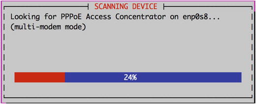
Figure 7-16. Checking for modem/concentrators
The first thing we do is search for a signal on the device like in 7-16. Next we are asked if we wish to modify the configuration files that pppoeconf changes.
Select yes like in Figure 7-17.
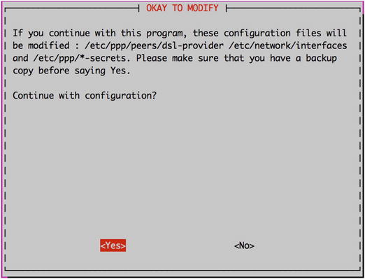
Figure 7-17. Okay to Modify?
Take the defaults in Figure 7-18.
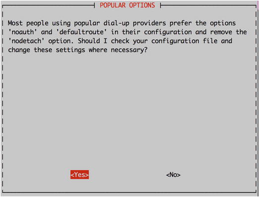
Figure 7-18. Popular options
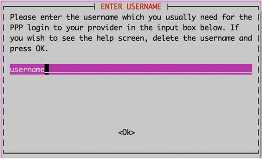
Figure 7-19. ISP username
Enter the ISP username you use to connect to the ISP.
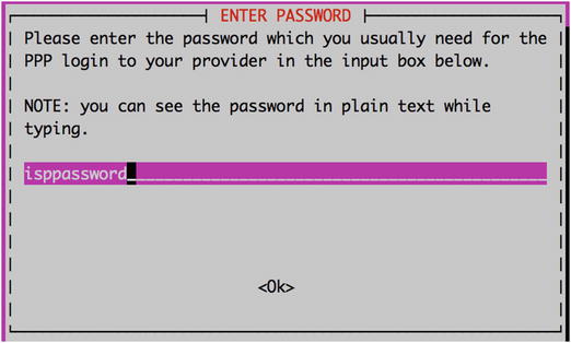
Figure 7-20. ISP password
Enter your ISP password.
Figure 7-21. Say No ot USER PEER DNS
We are going to say ‘no’, like we did with the CentOS configuration, for the DNS settings as we will manage them shortly. For the next screens we are going to select the defaults.
Figure 7-22. Clamp MSS at 1452.
Figure 7-23. Start the PPPOE connection at boot.
Figure 7-24. Start the DSL connections now?
Figure 7-25. Checking DSL connection
Once you have created a PPPoE device on Ubuntu, you will see that the ppp section has been added to /etc/network/interfaces file:
auto dsl-provideriface dsl-provider inet ppppre-up /bin/ip link set enp0s8 up # line maintained by pppoeconfprovider dsl-provider
Here you can see that an interface called dsl-provider is going to be created when the network is started, signified by auto dsl-provider. Next, notice that the device information will be provided by the provider dsl-provider. The provider information is found under the /etc/ppp/peers directory. Ubuntu has appended the following information to the end of our /etc/ppp/peers/dsl-provider file:
# Minimalistic default options file for DSL/PPPoE connectionsnoipdefaultdefaultroutereplacedefaultroutehide-password#lcp-echo-interval 30#lcp-echo-failure 4noauthpersist#mtu 1492#persist#maxfail 0#holdoff 20plugin rp-pppoe.sonic-enp0s8user "username"
The password information is stored here, in the /etc/ppp/chap-secrets file, and the contents are much like Listing 7-10.
If you are are not successful you can view connection logs via the plog command on Ubuntu or /var/log/messages on CentOS.
You should also check to make sure that your default route is set to the ISP’s first hop and that it is going out the right interface.
ip route showdefault via 10.1.1.1 dev adsl-enp0s8
In the above example, 10.1.1.1 would be your ISPs first hop and traffic will go out the adsl-enp0s8 interface if it is destined to leave your network.
For more information on setting up a connection on Ubuntu, please see:
Summary
In this chapter we have taken you through networking and the Linux Netfilter firewall. We talked about basic networking, how to manage Linux network interfaces and how to trouble shoot network issues. In this chapter covered how to do the following:
Configure interfaces on our host.
Netfilter basics
Firewalld and the firewall-cmd
The ufw tool for managing Ubuntu firewalls
The iptables tool for managing Linux firewalls
Logging, limiting and securing your connections
Use TCP Wrappers to secure your daemons.
Configure a PPP connection
In the next chapter, we will look at how to manage packages on a host. In that chapter, you will learn how to install, remove, and update software on your hosts.