
A. Connecting Your Studio
Your studio equipment needs will vary depending on which Pro Tools LE system you’re running—Digi 002, Digi 002 Rack, Mbox, Mbox 2, or Mbox 2 Pro—and the type of audio source, external hardware, and monitor system you want to connect it to.
If you already have a studio full of great-sounding peripheral hardware, don’t worry: You can connect all types of external hardware to Pro Tools LE systems. How many pieces of external hardware you can connect at one time, however, depends upon which Pro Tools LE system you’re using.
Connecting Your Studio to the Digi 002, Digi 002 Rack, Mbox, Mbox 2, or Mbox 2 Pro
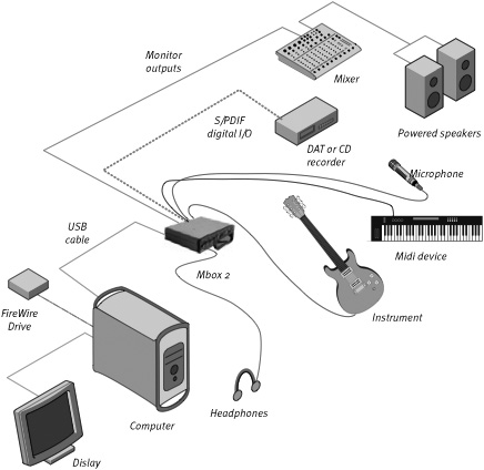
The minimum studio setup needed to record with Digi 002, Digi 002 Rack, Mbox, Mbox 2, and Mbox 2 Pro is a mic and mic cable (or instrument and instrument cable), and a pair of headphones. Figures A.1–A.4 show basic studio setups for Digi 002, Digi 002 Rack, Mbox, Mbox 2, and Mbox 2 Pro systems, respectively.
Figure A.1. A basic Digi 002 studio setup.
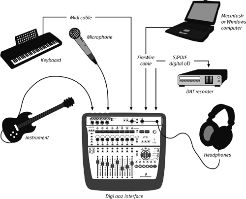
Figure A.2. A basic Digi 002 Rack studio setup.
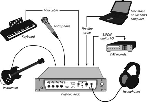
Figure A.3. A basic Mbox studio setup.
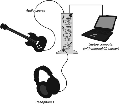
Figure A.4. A basic Mbox 2 or Mbox 2 Pro setup
With eight channels of analog I/O (including four balanced mic preamps with individual high pass filters) and 24-bit, 96 kHz A/D input signal conversion, Digi 002 and Digi 002 Rack give you the best audio quality and most input versatility of the LE systems.
Digi 002 and Digi 002 Rack also give you eight channels of optical I/O, two channels of S/PDIF digital I/O, and two alternate analog inputs (RCA plugs) for connecting an external sound source, such as a CD player or tape deck.
The original Mbox has far fewer I/O options than the Digi 002. You can, however, connect external hardware using the system’s two channels of analog I/O and two channels of S/PDIF digital I/O. Mbox also provides two 1/4-inch line inserts, which let you add external hardware effects during recording.
Mbox 2 and Mbox 2 Pro offer significantly more I/O options than the original Mbox.
The USB-based Mbox 2 audio interface includes two mic preamps (XLR), two 1/4-inch TRS inputs, and two DI inputs (1/4-inch TS). It also gives you two channels of S/DIF Digital I/O, two channel 1/4 (TRS) monitor outputs, as well as one MIDI In and one MIDI Out port.
The FireWire-based Mbox 2 Pro provides the same I/O features as the Mbox 2, with some key upgrades. The interface includes two built-in mic preamps (XLR-1/4-inch TRS combo jacks), which can record at sample rates up to 96 kHz. In addition, Mbox 2 Pro includes a two-channel auxiliary input section with both 1/4-inch TRS (balanced) and RCA stereo plug (unbalanced) inputs, It has four 1/4-inch TRS analog outputs, two channels of S/PDIF digital I/O, two channel 1/4 (TRS) monitor outputs, one MIDI In and one MIDI Out port, and Word Clock I/O.
Connecting Audio Sources to Digi 002 and Digi 002 Rack
The Digi 002 and Digi 002 Rack’s eight channels of balanced analog I/O (including four mic preamps) and 24-bit, 96 kHz A/D input signal conversion make them useful for live recording, studio sessions, or any situation requiring multiple high-quality mic or instrument inputs.
The Digi 002 and Digi 002 Rack have identical audio input controls, monitor controls, and status indicators, located on the front panels of their respective hardware interfaces (Figures A.5 and A.6) as follows:
Figure A.5. The Digi 002’s front panel includes Mic/Line/Inst Input controls, monitor controls, and status indicators (top section). The interface also includes transport controls, level faders with solo and mute buttons, and channel strip controls for sends, inserts, and pan (lower and middle sections).
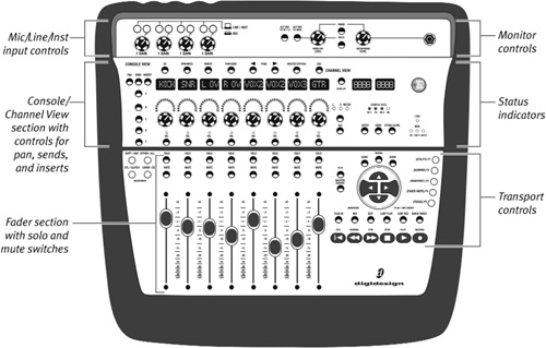
Figure A.6. The Digi 002 Rack’s front panel includes Mic/Line/Inst input controls, monitor controls, and status indicators.

• Mic/Line/Instrument selectors: These selectors let you toggle inputs between microphone and line-level operating levels. (Note: Toggling to mic position without a XLR mic cable attached may introduce low-level noise).
• High Pass Filter switch: This switch enables a high pass filter (75 Hz, 12 dB/octave rolloff) on the input. This filter is useful for reducing low-end rumble from sources such as air-conditioning units.
• Input Gain control: This knob lets you adjust input level of Mic/Line inputs 1–4.
Monitor Controls
• Monitor Level control: This knob controls the level of the Monitor Outputs. The Monitor Outputs mirror the Main Outputs (outputs 1–2).
• Monitor Mute switch: This switch mutes the Monitor Outputs only. It has no effect on the Main Outputs or Headphone Output.
• Mono Output switch: This switch combines output signals 1 and 2 in both the Monitor and Headphone outputs. This is useful for checking phase relationships of stereo material. The Mono Output switch has no effect on the Main Outputs.
• Headphone jack: This jack accepts a standard 1/4-inch stereo headphone connector.
• Headphone Level control: This knob lets you control headphone output level. Headphones let you monitor the Main Outputs (outputs 1 and 2).
Status Indicators
• Session Sample Rate indicators: The Session Sample Rate LEDs indicate the sample rate of the current Pro Tools session.
• Pro Tools Connection Status indicator: This LED, marked “1394,” indicates that communication has been established between the hardware interface and Pro Tools LE software via FireWire.
The Digi 002 and Digi 002 Rack’s respective back panels (Figure A.7a and A.7b) provide the following audio I/O features:
• Mic Inputs 1–4: These four balanced XLR mic preamps let you boost the input signals from microphones and other low-level audio sources requiring amplification.
• Line/Instrument Inputs 1–4: These four balanced 1/4-inch TRS inputs let you record line-level audio sources from line-level audio sources, such as keyboards, mixers, and preamps.
• Phantom Power switches: These switches let you apply 48V phantom power to Mic/Line inputs 1–2 and inputs 3–4, respectively.
• Analog Inputs 5–8: Analog inputs 5–8 accept balanced or unbalanced 1/4-inch connectors and are switchable between –10 dBV and +4 dBV line levels.
• Operating Level switches for Inputs 5–8: These switches let you switch the nominal line-level of channels 5–8 between –10 dBV and +4 dBV.
Figure A.7a and A.7b. The Digi 002 and Digi 002 Rack’s back panels.
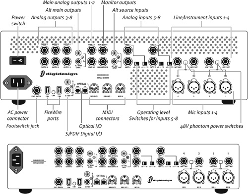
• Footswitch jack: Lets you connect a standard footswitch to punch in audio or MIDI when recording
• Alt Source Inputs: This pair of unbalanced RCA-connectors let you input audio from alternate sources such as a tape deck or CD player.
• Monitor Outputs: These balanced 1/4-inch TRS jacks let you monitor stereo output. These outputs play output routed to analog outputs 1 and 2 in Pro Tools.
• Main Analog Outputs 1–2: These balanced 1/4-inch TRS jacks output audio routed to analog outputs 1 and 2 in Pro Tools. These outputs are useful for stereo mixdown to an external stereo device (such as a two-track analog tape machine). Output is balanced, +4 dBu line-level.
• Analog Outputs 3–8: These balanced 1/4-inch TRS jacks output audio routed to analog outputs 3–8. Outputs are balanced, +4 dBu line-level.
• S/PDIF Digital I/O: These unbalanced RCA jacks input and output 24-bit digital data at sample rates up to 96 kHz. (See the sidebar Making Connections for more information on S/PDIF.)
• Optical I/O: This pair of optical connectors input and output eight channels of ADAT-format or two channels of S/PDIF-format digital audio. ADAT format supports sample rates of 44.1 and 48 kHz, whereas S/PDIF format supports sample rates up to 96 kHz. Both Optical formats support 16-bit, 20-bit, and 24- bit data resolution. (Select the desired Optical format in the Hardware Setup dialog.) Optical I/O uses standard optical “lightpipe” cables.
• MIDI I/O: The Digi 002 and Digi 002 Rack’s 5-pin MIDI connectors include one MIDI input and two MIDI outputs.
• Footswitch jack: Lets you connect a standard footswitch to punch in audio or MIDI when recording
• IEEE-1394 (FireWire) Ports: These two ports let you connect to your computer and external storage devices via FireWire. The Link LED (located between the FireWire ports) indicates an active connection is established between the interface and the computer.
To connect an analog audio source to the Digi 002 or Digi 002 Rack
• Connect either an XLR cable from a microphone or 1/4-inch TRS cable from a line-level device or instrument to any of the Mic/Line inputs 1–4 on the interface’s back panel. Mic preamps are necessary for microphones and instruments using magnetic pickups (such as electric guitars and other string instruments) that generate lower-level audio signals requiring amplification.
or
• Connect a balanced or unbalanced 1/4-inch cable from a line-level audio source (such as a keyboard, preamp, or mixer) to any of the analog inputs 5–8 on the interface’s back panel. If necessary, use the adjacent Operating Level switches for inputs 5–8 to switch between –10 dBV and +4 dBV line-level.
To connect a digital audio source to Digi 002 or Digi 002 Rack using optical cables
1. Connect an optical cable from the optical output of the external digital device to the optical input on the Digi 002 or Digi 002 Rack’s back panel.
2. Connect an optical cable from the optical output on the Digi 002 or Digi 002 Rack’s back panel to the optical input of the external digital device.
To connect a digital audio source to the Digi 002 using S/PDIF cables
• Connect a S/PDIF cable (75-ohm coaxial cable with RCA plugs) from the S/PDIF output of the external digital device to the S/PDIF input on the Digi 002 or Digi 002 Rack’s back panel.
• Each S/PDIF input and output carries a stereo signal. The following step is required only if you want to send a digital signal from Pro Tools to a digital device.
• Connect aanother S/PDIF cable from the S/PDIF output on the Digi 002 or Digi 002 Rack’s back panel to the S/PDIF input on the digital device.
For more information on connecting analog and digital hardware to Digi 002 and Digi 002 Rack, see Getting Started with Digi 002 and Digi 002 Rack.
Connecting Audio Sources to Mbox
Mbox provides two combination Mic/Line preamps. These Mic/Line preamp inputs accept either XLR (3-pin) or 1/4-inch TRS cables. Mbox also provides two channels of S/PDIF digital I/O.
The front panel of the Mbox (Figure A.8) has the following features:
• 48V LED: When lit, the 48V LED indicates that 48V phantom power is available at the Mic/Line input.
• Source selector: The Source selectors let you switch between three input level options for the Mbox’s Mic/Line inputs: Mic (microphone), Line, and Inst (Instrument).
• Gain controls: Gain controls let you adjust the input level of the Mic/Line inputs.
• Peak LEDs: Peak LEDs light up just below analog clipping levels. This warns you that the input signal may be approaching clipping.
• USB LED: The USB LED indicates that the USB port is active, and audio can pass in or out of the system.
• S/PDIF LED: The S/PDIF LED indicates that channels 1 and 2 are set to receive digital input (rather than analog).
• Mix (Ratio) control: The Mix (ratio) control lets you monitor an adjustable blend of live input signal (with zero latency) and audio playback from disk. To hear the input signal only, turn the Mix knob hard left to Input. To hear Pro Tools output only, turn the knob hard right to Playback.
• Mono switch: The Mono switch lets you hear live input signals in mono. You can use this switch to check for stereo phase cancellations. (Typically, out-of-phase tracks sound hollow and lacking in low frequencies.)
• Headphone gain: Headphone gain controls the output level of the headphones on both the front and back panels.
• Headphone output (front panel): The front panel headphone output is a 1/8-inch stereo mini connector. (Inserting a 1/4-inch TRS connector into the rear panel headphone disables the 1/8-inch headphone output on the front panel.)
Figure A.8. Mbox front panel.

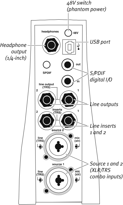
The back panel of the Mbox (Figure A.9) has the following features:
• Headphone output (back panel): The back panel headphone output features a 1/4-inch TRS connector.
• 48V switch: The 48V switch activates phantom power for use by microphones (especially condenser mics).
• USB port: The USB port lets you connect Mbox to any compatible USB-enabled computer.
• S/PDIF Digital I/O: S/PDIF digital inputs and outputs use RCA plugs.
• Line outputs: Line outputs are balanced TRS outputs, which you can connect to a mixer or stereo system to monitor mixes.
• Source 1 and 2: Combination Mic/Line (balanced/unbalanced) audio inputs. Accepts XLR (3-pin) or 1/4-inch TRS connections.
• Inserts 1 and 2: Inserts 1 and 2 are line inserts, which let you insert an effect into the audio input path of Source 1 and 2 inputs. The inserted effect is added to the analog audio input signal before it’s converted into digital audio. These inserts are useful for adding analog effects processors (such as equalizers and compressors) to a track.
Figure A.9. Mbox back panel.
To connect an analog audio source to the Mbox
• Connect an XLR or 1/4-inch cable to the Source 1 or Source 2 input on the Mbox’s back panel.
• Using the Source button on the Mbox’s front panel, select the input source type (mic, line, or instrument).
To connect a digital audio source to the Mbox
1. Connect a S/PDIF cable (75-ohm coaxial cable with RCA plugs) from the digital audio source’s S/PDIF output to the S/PDIF input on the Mbox’s back panel.
2. Connect another S/PDIF cable from the Mbox’s S/PDIF output to the digital audio source’s S/PDIF input.
Connecting Audio Sources to Mbox 2 and Mbox 2 Pro
The Mbox 2 and Mbox 2 Pro’s pairs of balanced mic preamps offer high-quality 24-bit analog to digital (A/D) audio conversion. And the Mbox 2 Pro’s 96 kHz sample rate recording capability place it on a par with many higher-end recording systems.
The Mbox 2 and Mbox 2 Pro audio interface front panels include the following features (Figures A.10 and A.11):
Audio Input 1–2 controls
Figure A.10. Mbox 2’s front panel
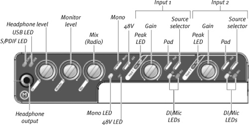
Figure A.11. The Mbox 2 Pro’s front panel
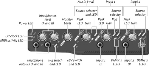
• Source selectors and LEDs: These selectors let you switch between Mic or DI inputs for that channel. The Mic and DI LEDs indicate the currently active input source. In addition, the Mbox 2 Pro’s front panel includes 1/4-inch DI input jacks for each channel.
• Gain controls: These knobs let you adjust the input gain levels (volume) of the Mic/Line inputs for each channel.
• Peak LED: The Peak LED indicates digital audio signal clipping on the input channel. If you see this light flickering red, reduce the audio input level using the Gain control knob and/or the output level of the external audio source. Also, try engaging the Pad switch to reduce input level.
• Pad: The Pad switch engages a –20 dB attenuation (reduction in level) on the input channel. If you notice the Peak LED is clipping, try using the Pad switch to cut the input level.
• Aux In 3–4(Line/Phono Inputs) (Mbox 2 Pro only): The Mbox 2 Pro has an additional pair of inputs with input connections for both balanced 1/4-inch TRS connectors and RCA phono plugs. Controls for the Aux 3–4 inputs on the front panel include a line/phono source selector, Gain controls, and Peak LEDs.
• 48V (Phantom Power) switch: The 48V switch activates phantom power, which is required for the operation of ultrasensitive condenser microphones. Dynamic microphones (such as the ubiquitous Shure SM57) do not require phantom power to operate. For more information on microphone types, see Chapter 6: Getting Ready to Record.
Monitor Controls
• Mix (Ratio): This knob lets you adjust a monitoring balance between your analog input signal and the output signal from Pro Tools. This feature can help reduce disorienting effects caused by latency (time delays between input and output signals) in host-based recording systems.
• Monitor Level control: This knob controls the level of the stereo (L/R) monitor outputs. This stereo signal is routed from Pro Tools outputs 1–2.
• Mono Output switch: This switch combines output signals 1 and 2 in both the monitor and headphone outputs. This is useful for checking phase relationships of stereo material. The Mono Output switch has no effect on the Main outputs.
• Headphone jacks: These jacks accept a standard 1/4-inch stereo headphone connector. The Mbox 2 Pro provides two headphone outputs (A and B).
• Headphone Level controls: This knob lets you control headphone output level. The Mbox 2’s single headphone lets you monitor the Main outputs 1–2. Mbox 2 Pro provides two separate headphone level controls: Headphone A and B.
• Headphone 3–4 switch and LED: This switch toggles Headphone B between Main outputs 1–2 and the output of channels 3–4.
Status Indicators
• S/PDIF LED: This LED indicates that Mbox 2 is using the S/PDIF inputs as the clock source.
• USB LED: This LED indicates that communication has been established between the hardware interface and Pro Tools LE software via USB.
• Ext Clock LED (Mbox 2 PRO): This LED indicates that S/PDIF or Word Clock I is the current clock source. When not lit, the clock source is internal.
• MIDI activity LED (Mbox 2 Pro): This LED indicates that Mbox 2 Pro is sending or receiving MIDI.
• Power LED: This LED indicates Mbox 2 Pro is powered on.
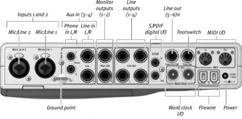
The Mbox 2 and Mbox 2 Pro respective back panels (Figures A.12 and A.13) provide the following audio I/O features:
• Inputs 1–2: Mbox 2 provides two balanced XLR mic inputs, two balanced 1/4-inch line inputs, and two DI inputs.
The Mbox 2 Pro provides two balanced XLR-1/4-inch (TRS) combo mic preamps and two DI inputs located on the interface’s front panel.
• Line outputs 1–4 (Mbox 2 Pro): These four balanced 1/4-inch TRS let you run additional speakers, run multiple effects, or setup additional headphone mixes during recording.
• Aux In 3–4 (Mbox 2 Pro): Aux In 3–4 provides jacks for RCA phono plugs and balanced 1/4-inch Line inputs. You can switch between connection types using the Aux IN 3–4 selector switch on the Mbox 2 Pro’s front panel.
• Line outputs 5–6 (Mbox 2 Pro): These two outputs let you run two channels of unbalanced output to an additional analog device.
• Footswitch jack: Lets you connect a standard footswitch to punch in audio or MIDI when recording
• Monitor Outputs 1–2: These balanced 1/4-inch TRS jacks output audio routed to analog outputs 1 and 2 in Pro Tools. These outputs are useful for stereo mixdown to an external stereo device (such as a two-track analog tape machine). Output is balanced, +4 dBu line-level.
• Word Clock I/O (Mbox 2 Pro): Word clock input and output are provided for synchronizing external recording devices with Pro Tools.
Figure A.12. The Mbox 2’s back panel
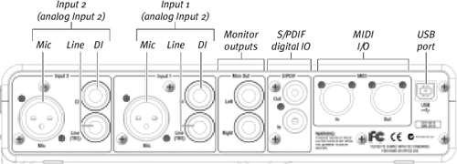
Figure A.13. The Mbox 2 Pro’s back panel
To connect an analog audio source to the Mbox 2 or Mbox 2 Pro
• Connect either an XLR cable from a microphone or 1/4-inch TRS cable from a line-level device or instrument to either of the Mic/Line inputs 1–2 on the interface’s back panel.
Mic preamps are necessary for microphones and instruments using magnetic pickups (such as electric guitars and other string instruments) that generate lower-level audio signals requiring amplification.
or
• Connect a balanced or unbalanced 1/4-inch cable from a line-level audio source (such as a keyboard, preamp, or mixer) to a DI input on the back panel of the Mbox 2 or DI input on the front panel of the Mbox 2 Pro.
To connect a digital audio source to Mbox 2 or Mbox 2 Pro
1. Connect a S/PDIF digital cable from the output of the external audio source to the S/PDIF input on the Mbox 2 or Mbox 2 Pro.
2. Connect a S/PDIF digital cable from the S/PDIF output on the Mbox 2 or Mbox 2 Pro to the input of the external digital device.
For more information on connecting analog and digital hardware to Mbox 2 or Mbox 2 Pro, see the Getting Started Guide that came with your system.
Connecting Audio Monitors
If you’re using Digi 002, Digi 002 Rack, Mbox 2, or Mbox 2 Pro, the easiest way to monitor audio is with headphones plugged into the jack on the front of their respective interfaces. Original Mbox users have two headphone options: a 1/8-inch stereo mini connector on the front panel and a 1/4-inch TRS connector on the rear panel. Mbox 2 and Mbox 2 Pro users have to use the 1/4-inch headphone jacks provided.
While monitoring over headphones is useful for hearing accurate stereo mixes, whenever possible, it’s best to monitor your audio through a set of speakers as well. Speakers give you a more accurate representation of how most listeners will experience your mixes—in a 3-dimensional space, over an average home stereo system.
Listening to headphones at even moderate volumes for prolonged periods can cause hearing damage and permanent ringing in the ears, or tinnitus. Always make sure your headphone volume is turned down before listening, and then turn the volume up slowly and carefully!
To connect monitor speakers to the Digi 002 or Digi 002 Rack
1. Connect 1/4-inch TRS cables to the left and right monitor outputs on the back of the Digi 002 or Digi 002 Rack.
2. Connect the 1/4-inch TRS cables to left and right inputs on your power amp, mixer, self-powered speakers, or home stereo.
Most home stereo systems use RCA connectors and will require an adapter.
To connect monitor speakers to the Mbox, Mbox 2, and Mbox 2 Pro
1. Connect 1/4-inch cables to the left and right monitor (or line) outputs on the back panel of the interface.
2. Connect the 1/4-inch cables to the corresponding left and right inputs on your power amp, mixer, self-powered speakers or home stereo.
Most home stereo systems use RCA connectors and will require an adapter.
• During the recording and mixing process, it’s useful to listen over as many different sets of speakers as possible. Most studios have small, medium-size, and large monitor speakers (some even have ultra-tiny and extra-large speakers), which can help you gain perspective on the frequency balance and overall sound quality of your mixes.
Connecting MIDI Devices
The Digi 002 and Mbox 2 systems’ built-in MIDI ports make it easy to connect MIDI devices (such as MIDI keyboard controllers, MIDI instruments, and sound modules). A MIDI driver for these ports is installed with Pro Tools LE and recognized by Midi Studio Setup (Windows) and Audio MIDI Setup (Macintosh).
Original Mbox users will need a third-party MIDI interface to record MIDI into Pro Tools LE.
For information on recording and editing MIDI in Pro Tools 7 LE, see Chapter 18: Recording MIDI and Chapter 19: Editing MIDI.
To connect a MIDI device to the Digi 002 or Digi 002 Rack
1. Connect a standard five-pin MIDI cable from the MIDI Out port on your MIDI device to the MIDI In port on the Digi 002 or Digi 002 Rack’s back panel.
2. Connect a standard five-pin MIDI cable from either of the two MIDI Out ports on the Digi 002 or Digi 002 Rack’s back panel to the MIDI In port on your MIDI device.
3. Connect the audio outputs of your device to an available audio input on the Digi 002 or Digi 002 Rack’s back panel.
To connect a MIDI device to Mbox 2 or Mbox 2 Pro
1. Connect a standard five-pin MIDI cable from the MIDI output on your MIDI device to the MIDI input on the Mbox 2 or Mbox 2 Pro’s back panel.
2. Connect a standard five-pin MIDI cable from the MIDI output on the Mbox 2 or Mbox 2 Pro box to the MIDI input on your MIDI device.
Connecting External Hardware Effects
Pro Tools lets you route both analog and digital audio signals to external hardware effects (such as equalizers, compressors, reverbs, and delays). Using the Digi 002, Digi 002 Rack, Mbox 2, or Mbox 2 Pro’s 1/4-inch analog inputs and outputs, or S/PDIF digital inputs and outputs, you can run several external hardware effects with your system.
The original Mbox has two 1/4-inch TRS inserts, which let you place effects into the path of analog audio entering Source 1 and Source 2 Mic/Line inputs. The inserted effect is added to the incoming signal before it’s converted into digital audio. These inserts are useful for adding effects such as equalizers and compressors to tracks during recording.
Connecting external analog hardware effects
To connect an external analog hardware effect to the Digi 002 or Digi 002 Rack
1. Connect a mono (single) or stereo (pair) output from analog outputs 5–8 to the corresponding inputs of the hardware effect.
2. Connect the outputs of the hardware effect to the corresponding analog inputs on the Digi 002 or Digi 002 Rack’s back panel.
To insert an external hardware effect on the Mbox’s input signal path
1. You’ll need a TRS Y cable (a TRS connector that splits into two unbalanced connectors).
2. Connect the unbalanced connector that corresponds to Tip to the input port of the hardware device.
3. Connect the unbalanced connector that corresponds to Ring to the output port of the hardware device.
4. Insert the TRS connector into the desired insert port on the Mbox.
Connecting external digital hardware effects
To connect an external digital hardware effect to the Digi 002 or Digi 002 Rack
• Connect the S/PDIF (RCA plug) inputs and outputs on the Digi 002 or Digi 002 Rack’s back panel to the corresponding inputs and outputs of the external digital hardware effect.
or
• If the hardware effect has optical inputs, connect the optical inputs and outputs on the Digi 002 or Digi 002 Rack’s back panel to the corresponding optical inputs and outputs of the external digital hardware effect.
To set up an effects loop between an external digital hardware effect and Digi 002 or Digi 002 Rack
1. Connect the digital inputs and outputs of the external digital hardware effect to the appropriate connectors (S/PDIF RCA connectors or Optical ports) of the Digi 002 or Digi 002 Rack.
2. In Pro Tools, choose Setup > Hardware.
3. Under Digital Input, select one of the following options:
• If the external effects device is connected to the S/PDIF RCA jacks, select “RCA = S/PDIF.”
• If the external effects device is a S/PDIF device connected to the Optical ports, select “Optical = S/PDIF.”
• If the external effects device is an ADAT Optical device, select “Optical = ADAT.”
4. Choose Internal from the Clock Source pop-up menu.
5. Click OK.
For more information on setting up effects loops, see Chapter 15: Adding Effects to a Mix.
• You can send signals to external hardware effects using the Mbox’s S/PDIF digital I/Os and analog I/Os.
• The I/O Setup dialog box lets you label channel inputs and outputs. This can help you keep track of sends and inserts during a session. For more information on I/O Setup, see Chapter 4: Starting a New Session.
• Most external hardware effects have 1/4-inch connectors. Higher-end units generally include both XLR and 1/4-inch connectors.