
3. The Mix and Edit Windows
Most of the action in Pro Tools takes place in two main windows: the Mix window and the Edit window. Learning the layout and features of these windows will help you master Pro Tools’ recording and editing features.
This chapter will introduce you to the main features of the Mix window, including channel strips, track controls, sends, inserts, and inputs and outputs. And you’ll learn how to adjust the display of the Mix window to get the most from limited screen space. You’ll learn the layout of the Edit window, too. I’ll point out important editing features such as Zoom buttons, Edit modes, Edit tools, and the Regions list. The latter is an invaluable tool for managing your audio files and MIDI data.
The Mix Window
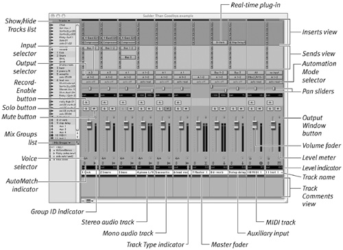
If you’re familiar with an analog mixing board, you’ll recognize the Pro Tools Mix window (Figure 3.1). It looks just like a hard-wired mixer, but it’s more flexible.
Figure 3.1. The Pro Tools Mix window.
1. Select Window > Mix, or Command-Equal (=) (Macintosh) or Control-Equal (=) (Windows).
The Mix Window appears.
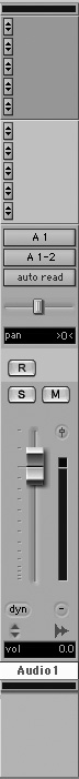
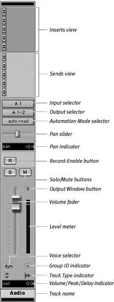
Each track in a Pro Tools session is displayed in the Mix window as a channel strip (Figure 3.2). Channel strips include track controls for inputs and outputs, volume, mute, solo, automation, and record-enable. Channel strips also include sections for sends, inserts, MIDI instrument controls, comments, and track color.
Figure 3.2. An audio track channel strip in the Mix window.
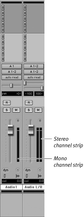
There are five types of channel strips: audio tracks, MIDI tracks, auxiliary inputs, instrument tracks, and master faders (Figure 3.3). All channel strips except MIDI tracks can be mono or stereo (Figure 3.4).
Figure 3.3. Channel strips. Each track type (audio, auxiliary input, master fader, MIDI, and Instrument) has a slightly different channel strip.
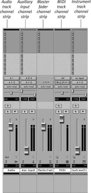
Figure 3.4. Mono and stereo audio track channel strips.
Audio track channel strips
Audio track channel strips (Figure 3.5) provide controls for audio volume, pan, solo, mute, record-enable, and automation. They also let you route channel inputs and outputs, sends, and inserts.
Figure 3.5. An audio track channel strip.
To create an audio track channel strip
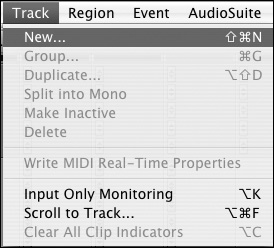
1. Select Track > New, or Shift-Command-N (Macintosh) or Shift-Control-N (Windows) (Figure 3.6).
Figure 3.6. Select Track > New.
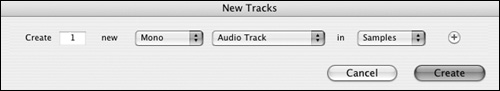
The New Tracks dialog box appears (Figure 3.7).
Figure 3.7. The New Tracks dialog box.
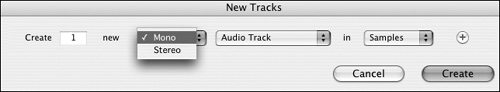
2. Select Mono or Stereo from the pop-up menu (Figure 3.8).
Figure 3.8. Select Mono or Stereo from the pop-up menu.
3. Select Audio Track from the pop-up menu (Figure 3.9).
Figure 3.9. Select Audio Track from the pop-up menu.

4. Enter the number of tracks and click Create.
MIDI track channel strips
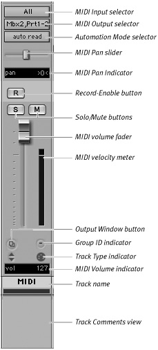
MIDI track channel strips (Figure 3.10) provide controls for volume, pan, solo, mute, and automation. You can also make MIDI patch assignments and MIDI channel assignments through this strip.
Figure 3.10. A MIDI track channel strip.
To create a MIDI track channel strip
1. Select Track > New, or Shift-Command-N (Macintosh) or Shift-Control-N (Windows).
The New Tracks dialog box appears.
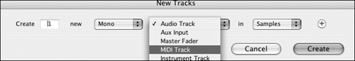
2. Select MIDI Track from the pop-up menu (Figure 3.11).
Figure 3.11. Select MIDI Track from the pop-up menu.
3. Enter the number of tracks and click Create.
Auxiliary input channel strips
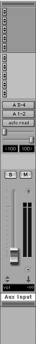
Auxiliary input channel strips (Figure 3.12) are similar to audio track channel strips, but they accept input only from internal bus or external hardware sources.
Figure 3.12. An auxiliary input channel strip.
You can use an auxiliary input to create an effects loop, in which audio is routed to an auxiliary input, and an effect (such as EQ, compression, or reverb) is added. The effects return is then routed to the main mix. For more information on effects loops, see Chapter 15: Adding Effects to a Mix.
You can also use auxiliary inputs to create submixes. This lets you consolidate multiple tracks of audio onto one channel strip. For more information on submixes, see Chapter 14: Mixing Basics.
To create an auxiliary input channel strip
1. Select Track > New, or Shift-Command-N (Macintosh) or Shift-Control-N (Windows).
The New Tracks dialog box appears.
2. Select Mono or Stereo from the pop-up menu.
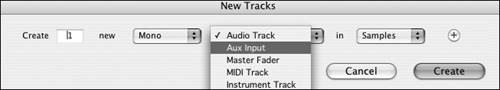
3. Select Auxiliary Input from the pop-up menu (Figure 3.13).
Figure 3.13. Select Auxiliary Input from the pop-up menu.
4. Enter the number of auxiliary inputs and click Create.
Instrument track channel strips
Instrument track channel strips (Figure 3.14) combine features of audio track channel strips and MIDI track channel strips.
Figure 3.14. An Instrument track channel strip.
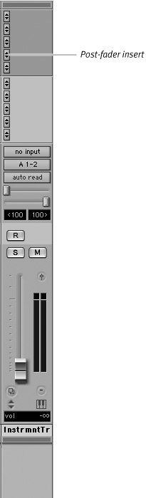
You can use an instrument track to record MIDI data while monitoring the audio output of a triggered MIDI device. For more information on recording MIDI, see Part VI: MIDI Sequencing.
To create an instrument track channel strip
1. Select Track > New, or Shift-Command-N (Macintosh) or Shift-Control-N (Windows).
The New Tracks dialog box appears.
2. Select Mono or Stereo from the pop-up menu.
3. Select Instrument Track from the pop-up menu (Figure 3.15).
Figure 3.15. Select Instrument Track from the pop-up menu.
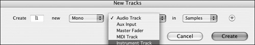
4. Enter the number of instrument tracks and click Create.
Master fader channel strips
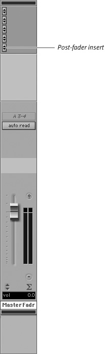
Master fader channel strips (Figure 3.16) let you control the output level of the main mix. You can also use them to control output levels for submixes, bus paths, sends, and inserts.
Figure 3.16. A stereo master fader channel strip.
To create a master fader channel strip
1. Select Track > New, or Shift-Command-N (Macintosh) or Shift-Control-N (Windows).
The New Tracks dialog box appears.
2. Select Mono or Stereo from the pop-up menu.
3. Select Master Fader from the pop-up menu (Figure 3.17).
Figure 3.17. Select Master Fader from the pop-up menu.
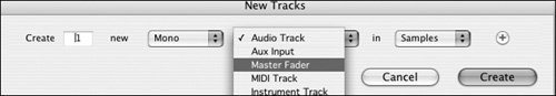
4. Enter the number of master faders and click Create.
• The inserts section of a master fader is always post-fader. This means that the inserts occur in the signal path after the track’s fader. (The inserts section of audio tracks and auxiliary inputs is always pre-fader.)
• Post-fader inserts are convenient for adding an effect, such as an aural exciter or dither, to the main mix. But avoid the temptation to add compression or other dynamic effects to the main mix. Compression can make a mix sound boxy, and it can also remove audio information that a mastering engineer may want to more precisely sculpt using EQ and other effects. Compression can also change the overall level of a mix and create audible inconsistencies between mixes.
For more information about track types and creating new tracks, see Chapter 5: Working with Tracks.
Viewing Channel Strips
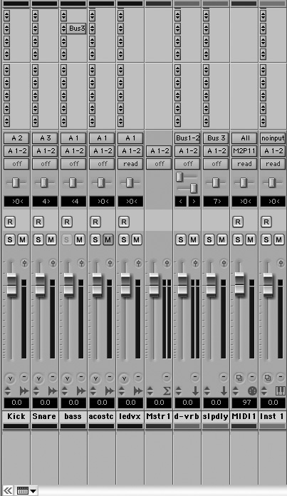
The Mix window is dedicated primarily to the display of track channel strips. You can expand, contract, and narrow the view of channel strips according to your needs (Figure 3.18).
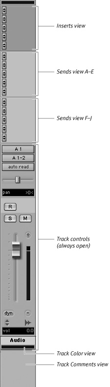
Figure 3.18. The view of a fully expanded channel strip.
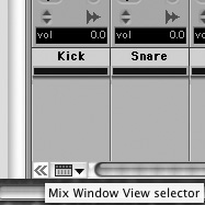
Pro Tools 7 introduces the convenient Mix Window View selector (lower-left corner of Mix Window), which lets you quickly adjust the display of channel strips (Figure 3.19)
Figure 3.19. The Mix Window View selector lets you quickly expand the view of channel strips in the Mix window.
A fully expanded channel strip displays:
• Track controls (always open)
• Sends (A–E) and (F–J)
• Inserts
• Track comments
• Track colors
To view expanded channel strips
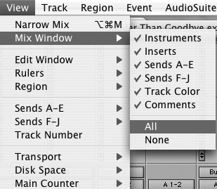
• Select View > Mix Window > All (Figure 3.20).
Figure 3.20. Select View > Mix Window > All.
or
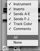
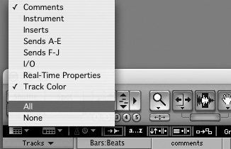
• Click the Mix Window View selector and select All (Figure 3.21).
Figure 3.21. The Mix Window View selector pop-up menu.
To view narrow channel strips
• Select View > Narrow Mix (Figure 3.22). The Mix window displays narrow channel strips (Figure 3.23).
Figure 3.22. Select View > Narrow Mix.
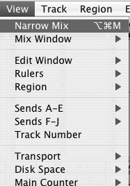
Figure 3.23. The Narrow Mix window view.
Track controls
Channel strips in the Mix window offer track controls for recording and playing back audio and MIDI tracks (Figure 3.24). Audio and MIDI track channel strips have the following track controls:
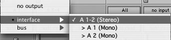
Input selectors: Input selectors let you route audio inputs or internal busses to an audio track or auxiliary input (Figure 3.25). Available inputs depend on your I/O Setup configuration.
Output selectors: Output selectors let you route audio to any available audio output or internal bus (Figure 3.26). Available outputs depend on your I/O Setup configuration.
Automation mode: The Automation mode selector lets you control how track automation is written and played back. You can choose from Auto Off, Auto Read, Auto Write, Auto Touch, and Auto Latch modes. For more information on automation modes, see Chapter 16: Automating a Mix.
Pan slider: The Pan slider controls the balance of a track between left and right output channels. Pan sliders appear on the channel strips of stereo tracks or mono tracks routed to a stereo output.
Pan indicator: The Pan indicator shows you the left and right output balance of a track. Pan values range from <100 (full left) to >100 (full right).
Record-Enable: The Record-Enable button puts audio and MIDI tracks into Record-Ready mode. Once a track is record-enabled, click the Record button, and then the Play button in the Transport window to start recording.
Solo: The Solo button mutes all tracks except the soloed track. This lets you monitor a track by itself. You can solo multiple tracks simultaneously.
Mute: The Mute button silences a track. You can mute multiple tracks simultaneously.
Output Window button: The Output Window button opens a separate floating channel strip. Output windows provide controls for track output.
Volume fader: The Volume fader controls the monitor volume of a track in playback, as well as the monitor volume of a track in record.
Level meter: The Level meter displays an audio signal’s volume level as it’s recorded to the hard disk. It also displays a signal’s volume level as it’s played back from the hard disk.
The color of the Level meter light indicates the status of the audio signal: Green indicates nominal (safe) levels, yellow indicates pre-clipping, and red indicates clipping.
Voice selector: In Pro Tools 7 LE, the Voice selector lets you toggle between Dynamic voice selection and Off. When set to Dynamic voice selection, Pro Tools automatically assigns voices to a track. When set to Off, a track’s voice assignment remains unchanged.
Volume/Peak/Delay indicator: The Volume/Peak/Delay indicator shows the current volume input level, the most recent peak playback level, and on Pro Tools HD systems, the delay time in samples incurred by a TDM plug-in on that channel. Command-click (Macintosh) or Control-click (Windows) the indicator to switch between level, peak, and delay.
Track Name: When you create a track with the New Track command, it’s automatically given a track name.
Figure 3.24. Track controls for an audio track channel strip in the Mix window.
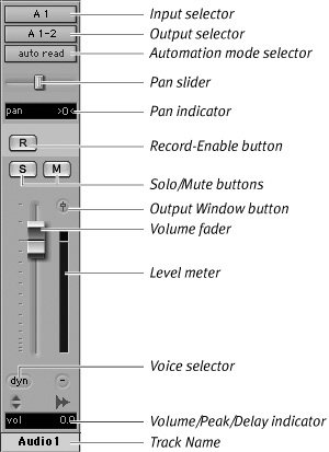
Figure 3.25. Input selectors let you route audio input.
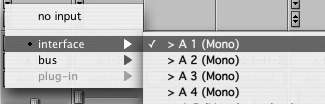
Figure 3.26. Output selectors let you route audio output.
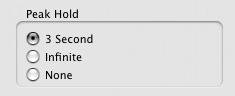
• Use the Pro Tools Preferences window to adjust a Peak Hold setting for the Track Level meter. This will help you monitor input and output levels. Select Setup > Preferences (Figure 3.27), click the Display tab, and then choose from three Peak Hold settings: 3 Second, Infinite, or None (Figure 3.28).
Figure 3.27. Select Setup > Preferences.
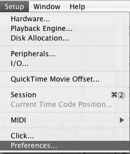
Figure 3.28. In the Preferences dialog box, click the Display tab, and then choose a Peak Hold option.
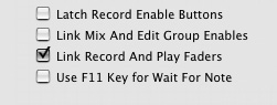
• Pro Tools remembers both record and playback fader levels for each audio track. Linking these faders in the Pro Tools Preferences window will keep them from changing position when you record-enable a track. Select Setup > Preferences, click the Operation tab, and then select the Link Record And Play Faders check box (Figure 3.29).
Figure 3.29. Select the Link Record And Play Faders check box in the Operation Preferences dialog box.
• To rename a track, double-click the track name at the bottom of a channel strip. A dialog box appears (Figure 3.30). Enter the new track name and click OK.
Figure 3.30. The Rename Track dialog box.
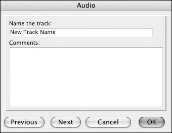
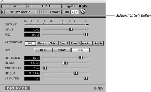
Figure 3.31. The Automation Safe button prevents you from overwriting previously recorded automation.
The Sends view
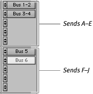
Sends let you route audio to internal busses or external outputs for effects processing or submixing. In Pro Tools 7, you can assign up to ten sends per audio track, auxiliary input, or instrument track. Sends are divided into two views: Sends A–E and Sends F–J (Figure 3.32).
Figure 3.32. The Sends A–E view and the Sends F–J view.
To show the Sends A–E view or the Sends F–J view
• Select View > Sends A–E or Sends F–J.
or
• Click the Mix Window View selector and select Sends A–E or Sends F–J.
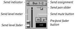
Output parameters for sends include level, pan, mute, and pre- and post-fader. To control send parameters, you can use either the Sends Output window (Figure 3.33) or the individual send controls (Figure 3.34) that appear within the Sends view.
Figure 3.33. A Sends Output window.
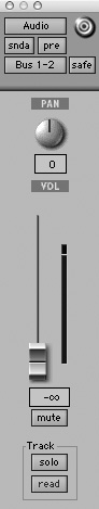
Figure 3.34. Individual send controls.
To open a Sends Output window
• Click any Send button to open a Sends Output window.
To open individual send controls
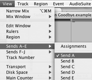
1. Select View > Sends A–E or Sends F–J.
2. Select an individual send (Send A through Send E) or (Send F through Send J) (Figure 3.35). Individual send controls appear in the Sends View section. For more information on Sends, see Chapter 15: Adding Effects to a Mix.
Figure 3.35. To display individual send controls, select View > Sends A–E or Sends F–J. Then select a send (Send A through Send E or Send F through Send J).
The Inserts view
Inserts let you add effects on individual channel strips. The Inserts view (Figure 3.36) lets you access five pre-fader inserts per audio track, auxiliary input, or instrument track You can assign internal software effects and external hardware effects to inserts.
Figure 3.36. The Inserts view.

To show the Inserts view
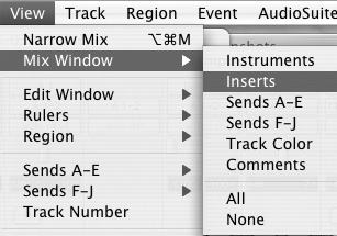
• Select View > Mix Window > Inserts (Figure 3.37).
Figure 3.37. Select View > Mix Window > Inserts.
or
• Click the Mix Window View selector and select Inserts.
The Inserts view also gives you access to Effects Plug-in windows.
To show an Effects Plug-in window
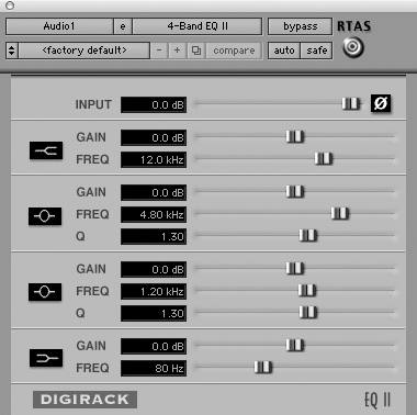
• Click an assigned Insert button (Figure 3.38). The assigned Effects Plug-in window opens (Figure 3.39).
Figure 3.38. Click an assigned Insert button to show its Effects Plug-in window.

Figure 3.39. An open Effects Plug-in window (4-Band EQII).
The Track Color view
In Pro Tools 7 you can color code your tracks using the Track Color view.
To show the Track Color view
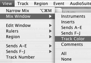
• Select View > Mix Window > Track Color (Figure 3.40).
Figure 3.40. To show the Track Color view, select View > Mix Window > Track Color.
or
• Click the Mix Window View selector and select Track Color.
For more information on color coding tracks, see Chapter 5: Working with Tracks
The Track Comments view
The Track Comments view shows any comments entered into the Track Name/Comments dialog box.
To show the Track Comments view
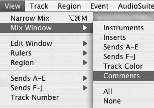
• Select View > Mix Window > Comments (Figure 3.41).
Figure 3.41. To show the Track Comments view, select View > Mix Window > Comments.
or
• Click the Mix Window View selector and select Comments.
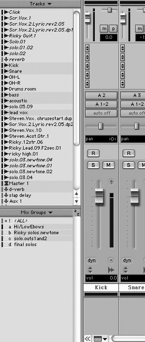
The Tracks list
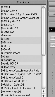
The Tracks list (Figure 3.42) in the Mix window displays the names of all the tracks in the current session. You can show or hide a track by selecting or deselecting it, and you can rearrange tracks by dragging them up or down.
Figure 3.42. The Tracks list in the Mix window.
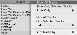
The Tracks pop-up menu at the top of the list gives you options for showing, hiding, and sorting tracks (Figure 3.43).
Figure 3.43. The Tracks list pop-up menu.
The Mix Groups list
The Mix Groups list (Figure 3.44) in the Mix window shows all the mix groups in a session. You can enable a group by highlighting its name in the list.
Figure 3.44. The Mix Groups list.
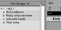
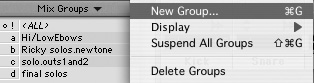
The Mix Groups pop-up menu at the top of the list lets you create new groups; display edit groups or mix groups; and suspend or delete groups (Figure 3.45).
Figure 3.45. The Mix Groups pop-up menu.
Viewing the Tracks list and the Mix Groups list
The Tracks list and the Mix Groups list are displayed at the left of the Mix window. You can open and close this section of the Mix window as needed to accommodate the display of track channel strips.
To open/close the Tracks list and the Mix Groups list
• Click the double arrow at the bottom left of the Mix Window (Figure 3.46).
Figure 3.46. To open/close the Tracks list and the Mix Groups list, click the double arrow icon in the lower-left corner of the Mix window.
![]()
The Tracks list and the Mix Groups list appear at the left side of the Mix window (Figure 3.47).
Figure 3.47. The Tracks list and the Mix Groups list in the Mix Window.
• If a hidden track is part of a group, operations performed on the group will be performed on the hidden track as well. Disable groups with hidden tracks to avoid making unwanted changes. For information on enabling and disabling groups, see Chapter 5: Working with Tracks.
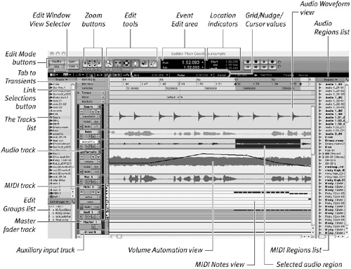
The Edit Window
The Edit window (Figure 3.48) gives you a visual read-out of audio, MIDI, and automation data against a timeline. It also offers tools for selecting, viewing, and arranging this recorded data. In addition, the Edit window features tools for managing audio files and MIDI files.
Figure 3.48. The Pro Tools Edit window.
• Select Window > Edit, or Command-Equal (=) (Macintosh) or Control-Equal (=) (Windows).
The Edit Window appears.
Viewing the Edit window
The Edit window displays the same channel strips as in the Mix window, with a few additional features outlined below. You can expand the Edit window to view the full channel strips, but they are displayed horizontally, not vertically.
In Pro Tools 7, the Edit window includes an Edit Window View selector, which lets you quickly customize the view of channel strips.
To view expanded channel strips in the Edit window
• Select View > Edit Window > All.
or
• Click the Edit Window View selector and select All (Figure 3.49).
Figure 3.49. To view a fully expanded channel strip in the Edit window, click the Edit Window View selector and select All.
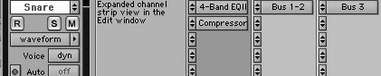
The expanded channel strip view appears (Figure 3.50).
Figure 3.50. An expanded channel strip in the Edit window.
For more information on channel strips, see The Mix Window section earlier in this chapter.
• Edit Window channel strips, unlike Mix Window channel strips, include an I/O (Input/Output) View, which shows track input and output assignments. You can hide the I/O View to conserve track viewing space. To show or hide the I/O View, select Display > Edit Window Shows > I/O View.
• To toggle between the Mix and Edit windows, press Command-Equal (=) (Macintosh) or Control-Equal (=) (Windows).
Track controls
Most of the Edit window’s track controls (Figure 3.51) are identical to those in the Mix window. For information on Record-Enable, Solo, Mute, Automation mode selector, and Track Name, see the Track Controls section earlier in this chapter.
Figure 3.51. The Edit window track controls.
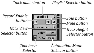
In addition to the above track controls, the Edit window contains the following:
• Playlist selector: The Playlist selector lets you create and manage multiple edit playlists on each track (Figure 3.52).
Figure 3.52. The Playlist selector.
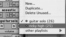
An edit playlist is a snapshot of the current arrangement of regions on a track. Edit playlists gives you the flexibility to experiment with region editing ideas. For more information on playlists, see Chapter 2: Software Basics, and Chapter 10: Editing Basics.
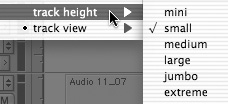
• Track Height selector: The Track Height selector lets you adjust the vertical size of a track. You can select from mini, small, medium, large, jumbo, and extreme (Figure 3.53). You can also toggle back and forth between track height settings.
Figure 3.53. The Track Height selector.
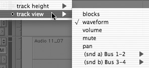
• Track View selector: Although you’ll mainly use the Waveform view, the Track View selector lets you see a visual read-out of other track information. On audio tracks you can select from blocks, volume, pan, mute, send level, send mute, and send pan (Figure 3.54).
Figure 3.54. The Track View selector.
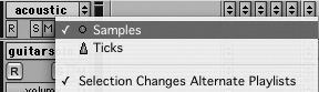
• Timebase selector: The Timebase selector lets you switch individual tracks between tick-based timing and sample-based timing (Figure 3.55).
Figure 3.55. The Timebase selector.
Edit modes
The Edit window’s four Edit Mode buttons (Figure 3.56) let you choose how regions are moved in the window. You can select from the following modes:
• Shuffle: Shuffle mode automatically snaps a region to the end of another region. For instance, if you select an audio region and delete it, the region to the right snaps to the region on the left.
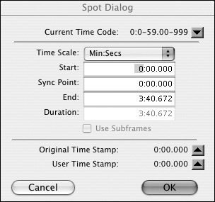
• Spot: Spot mode lets you move a selected region to an exact time location. When you move a selected region in Spot mode, the Spot dialog box opens (Figure 3.57). This lets you enter a new start time for the selected region.
• Slip: Slip mode lets you move regions freely in a track, with few limitations. In Slip mode you can overlap regions or separate regions with space (silence).
• Grid: Grid mode lets you snap selected regions to a user-defined time grid.
Figure 3.56. The Edit Mode buttons.
![]()
Figure 3.57. The Spot Mode dialog box. Move a selected region by entering a new start time.
• To switch between edit modes, use the following function keys: F1 (Shuffle), F2 (Slip), F3 (Spot), F4 (Grid).
For more information on Edit modes, see Chapter 10: Editing Basics.
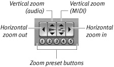
Zoom buttons
The Edit window’s Zoom buttons (Figure 3.58) let you zoom quickly in and out of audio and MIDI tracks. Zoom buttons include:
• Horizontal Zoom In/Out: Zooms in and out horizontally on a track. Option-click (Macintosh) or Alt-click (Windows) either Horizontal Zoom button to restore the previous zoom level.
• Vertical Zoom In/Out (audio): Zooms in and out vertically on audio tracks. Option-click (Macintosh) or Alt-click (Windows) either Vertical Zoom button to restore the previous zoom level.
• Vertical Zoom In/Out (MIDI): Zooms in and out vertically on a MIDI track. Option-click (Macintosh) or Alt-click (Windows) either Vertical Zoom button to restore the previous zoom level.
• Zoom Presets: You can save up to five horizontal zoom presets. Command-click (Macintosh) or Control-click (Windows) any Zoom Preset button to save the current horizontal zoom value.
Figure 3.58. The Zoom buttons.
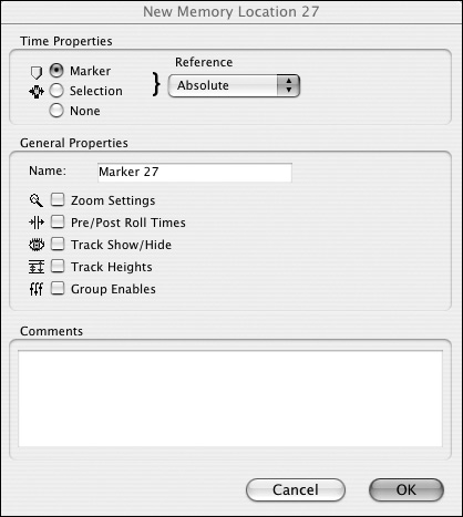
• You can save zoom settings in the Memory Location dialog box (Figure 3.59) when you enter a memory location. You’ll find details for setting memory locations in Chapter 10: Editing Basics.
Figure 3.59. Memory Location dialog box. Press Enter on the numeric keypad to set a new memory location.
Edit tools
The Edit window’s Edit tools (Figure 3.60) let you select, audition, view, and move regions. The tools include:
• Zoomer: The Zoomer tool lets you zoom in quickly on a track. To zoom in horizontally, click or drag the Zoomer tool. To zoom in horizontally and vertically, press Command (Macintosh) or Control (Windows) while dragging.
• Zoom Toggle: The Zoom Toggle lets you switch back and forth between the current zoom view and a predefined zoom view.
• Standard Trimmer: The Standard Trimmer tool lets you quickly expand or condense a region. To use it, click or drag near the start or end point of the region.
• Time Trimmer: The Time Trimmer tool lets you expand or compress a region by dragging its start or end points. The Time Trimmer uses the Time Compression/ Expansion AudioSuite plug-in to create a new file. For more information on AudioSuite plug-ins, see the DigiRack Plug-Ins Guide.
• Selector: The Selector tool lets you make a selection anywhere on a track by clicking and dragging. To adjust the length of a selection, Shift-click or Shift-drag with the Selector. To extend an edit selection to other tracks, Shift-click with the Selector in the desired tracks.
• Time Grabber: The Time Grabber tool lets you select and move regions anywhere within a track or between tracks by clicking and dragging. To move a region with the Time Grabber, select a region and drag it to a new location.
• Separation Grabber: The Separation Grabber tool lets you separate and move a region within or between tracks. To separate regions, click a selected region with the Separation Grabber.
• Scrubber: The Scrubber tool lets you audition or scrub audio regions. Scrubbing—a term borrowed from analog recording—refers to running the tape manually back and forth over the playback head. Scrubbing is useful for locating edit points that might be difficult to find visually. To scrub a track, click and drag the Scrubber tool over an audio region (Figure 3.61).
• Pencil: The Pencil tool lets you insert MIDI notes, edit MIDI note velocities, draw automation and controller events, and repair audio waveforms at the sample level. Clicking the Pencil tool summons its pop-up menu (Figure 3.62), which lets you choose from seven Pencil shapes.
Figure 3.60. The Edit tools.
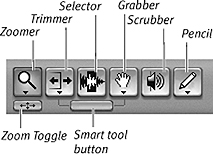
Figure 3.61. Run the Scrubber tool over an audio region to scrub audio.
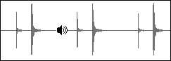
Figure 3.62. The Pencil tool pop-up menu.
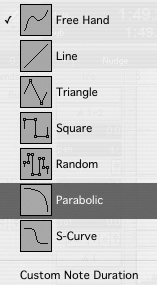
You can also use the Pencil tool as an eraser to delete notes, program changes, and sysex events. Press Option (Macintosh) or Alt (Windows) to change the Pencil tool to an Eraser.
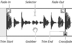
• Smart Tool: The Smart tool (Figure 3.63) lets you use several Edit tools without having to switch between them. As you move the Smart tool within a region, it automatically changes between the Selector, Grabber, and Trimmer, and lets you create fades as well (Figure 3.64).
Figure 3.63. The Smart tool lets you use several Edit tools simultaneously.

Figure 3.64. The Smart tool automatically changes between the Selector, Grabber, and Trimmer tools as you move your cursor over a region. You can also create fades with the tool.
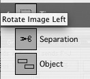
• Use the Grabber pop-up menu (Figure 3.65) to choose between the Time Grabber, Separation Grabber, and Object Grabber. Clicking the Grabber tool summons the pop-up menu. The Time Grabber is the default Grabber tool.
Figure 3.65. The Grabber tool pop-up menu.
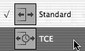
• Use the Trimmer pop-up menu (Figure 3.66) to choose between the Standard Trimmer and the Time Trimmer. Clicking the Time Trimmer tool summons the pop-up menu. The Standard Trimmer is the default Trimmer tool.
Figure 3.66. The Trimmer pop-up menu.
• Use the following function keys to select and/or toggle Edit tools: F5 (Zoomer), F6 (Standard Trimmer), F7 (Selector), F8 (Time/Separation Grabber), F9 (Scrubber), F10 (Pencil), F6 and F7 simultaneously (Smart tool).
The Event Edit area
The Edit window’s Event Edit area (Figure 3.67) displays the start point, end point, and length of a selected region or note. The selection indicators display a selection in minutes and seconds, bars and beats, or samples, depending on the current time format of the Main Time Scale (see Location indicators later in this chapter).
Figure 3.67. The Event Edit area showing the start time, end time, and length of an audio region selection.
![]()
When you select a MIDI note, the right side of the Event Edit area displays MIDI note attributes such as pitch, attack velocity, and release velocity. You can change the value of a selection indicator or note attribute by entering a new value in its field.
• Press slash (/) on the numeric keypad to select the start field and to navigate from field to field. Press Enter to accept a new value.
Location indicators
The location indicators (Figure 3.68) display the current play position in both the Main time scale and Sub time scale.
Figure 3.68. Location indicators show the Main time scale and Sub time scale.
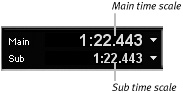
The Main time scale is the primary time format of your session (see time formats, below). The Sub time scale is an additional timing reference that can be useful with synchronization. To change the time format of either scale, click the pop-up menu to the right of its field (Figure 3.69).
Figure 3.69. Click the Location indicator pop-up menu to change the Main and Sub time scale time formats (Bars:Beats, Min:Secs, or Samples).
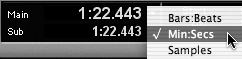
You can choose from these time formats:
• Bars:Beats
• Minutes:Seconds (Min:Secs)
• Samples
• Press Equal (=) on the numeric keypad to select the Main time scale in the location indicator. Press period (.) to navigate the indicator’s time fields; press Enter to go to a new location.
Grid/Nudge values, Current Cursor display
The Edit window also provides fields for quickly entering Grid and Nudge values during editing. The Current Cursor display gives you information about the location of the cursor.
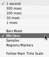
• Grid value: The Grid value field (Figure 3.70) lets you define the size of the grid used in Grid mode. You can define a Grid value that matches the time format currently used by the Main time scale, or select a different time format from the pop-up menu to the right of the field (Figure 3.71). For more information on using grids, see Chapter 10: Editing Basics.
Figure 3.70. The Grid value, Nudge value, and Current Cursor location value.
![]()
Figure 3.71. Select a new Grid value or time format using the Grid value pop-up menu.
• Nudge value: The Nudge value field lets you define the distance you can nudge a selected region with the plus and minus keys on the numeric keypad. Use the pop-up menu to the right of the field to select a nudge value. For more information on the Nudge feature, see Chapter 10: Editing Basics.
• Cursor location: The Cursor location field displays the location of the cursor in the same time format as the current Main time scale.
• Cursor value: The Cursor value field displays information about the cursor location based on the current track view. For instance, Volume view shows a dB value, Note view shows a MIDI note value, and Velocity view shows a velocity value.
The Edit Groups list
Much like the Mix Groups list in the Mix window, the Edit Groups list (Figure 3.72) displays all the edit groups in a session. You can enable or disable a group by selecting its name in the Groups list. Highlighted groups are enabled.
Figure 3.72. The Edit Groups list.
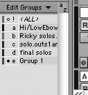
To create a new group, or suspend or delete groups, use the Edit Groups pop-up menu at the top of the list. For more information on groups, see Chapter 5: Working with Tracks.
The Regions list
Audio regions, MIDI regions, and region groups appear in the Regions list (Figure 3.73). You can drag regions from the list onto any audio or MIDI track.
Figure 3.73. The Regions list.
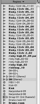
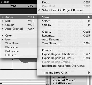
The Regions list has an indispensable pop-up menu (Figure 3.74), which lets you import, sort, compact, and delete audio files, MIDI regions, and region groups. For more information on handling audio files, see Chapter 8: File Management Basics.
Figure 3.74. The Regions List pop-up menu lets you import, sort, compact, and delete audio files.
Viewing the Regions list
The Regions list is displayed at the right side of the Edit window. You can open and close this section of the Edit window as needed to accommodate the display of tracks.
To open/close the Regions list
• Click the double arrow at the bottom right of the Edit window.
The Regions list appears at the right side of the Edit window.
Displaying Transport controls in the Edit window
In Pro Tools 7, you have the option of displaying a scaled-down version of the Transport window at the top of the Edit window (Figure 3.75). This can save you the time it takes clicking back and forth between separate Edit and Transport windows, and thus can increase your editing efficiency.
Figure 3.75. To display transport controls in the Edit window, select View > Edit Window > Transport.
![]()
To display Transport controls in the Edit window
• Select View > Edit Window > Transport.
For more information on the Transport Window, see Chapter 7: Recording and Playing Back Audio.