
In our final masterclass, we're going to look at ways to detect infiltrations and protect ourselves against other would-be spies. To help us do this, we will be plugging sensors and other gadgets into our Raspberry Pi so we can be alerted when people stray into our territories.
The Raspberry Pi has lots of ways of connecting things to it, such as plugging things into the USB ports, connecting devices to the onboard camera and display ports, and to the various interfaces that make up the GPIO (General Purpos Input/Output) connector. As part of our detection and protection regime, we'll be focusing mainly on connecting things to the GPIO connector.
During this chapter we will:
- Explore the GPIO and how to connect things safely to it
- Build a laser trip wire to protect corridors and entrances
- Protect areas of space using a passive infrared detector
- Send messages to our phone using SMS rather than e-mail
- Gain access to certain files on your Pi using your mobile phone as an access control device
- Send secret encoded messages to your fellow agents using an LED display
- Use the Pi Zero as a portable hardware random number generator to improve encryption on other PCs and servers.
The GPIO connector is the large group of pins on the edge of your Raspberry Pi board. On earlier models, there were 26 pins that made up this connector. Since the Model B+ there are now 40 pins, although the first 26 pins are identical to the previous models, and it's these 26 pins we'll be working with. You won't need to worry about the rest of the pins.
Essentially, the GPIO connector provides access to:
- Power supplies
- Digital I/O pins
- I2C bus
- SPI bus
- UART Serial bus
Some of the pins on the GPIO have more than one purpose, depending on how they are programmed. The following diagram is a reference guide to all of the pins on the GPIO. The GPIO numbers on the yellow labels relate directly to those on the Broadcom chip, and are numbers generally used within the scripts:
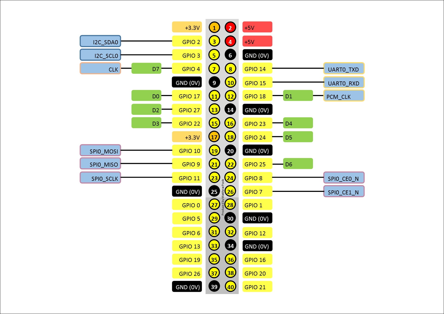
The GPIO connector also provides access to the onboard power supplies. The +5V connection (pins 2 and 4) is essentially the +5V input from the external power supply connected to the micro-USB power port. This can be used to power small external circuits if necessary, although it is recommended that an additional external +5V supply is used, if significant current is required.
The +3.3V supply (pins 1 and 17) is the output from the onboard 3.3V regulator, and provides a small amount of current up to 50mA. If you need to draw more than 50mA for your external circuits then you should use an external power supply.
IMPORTANT: The I/O pins on the Raspberry Pi operate at 3.3V levels. Connecting voltages higher than this to the pins could irreversibly damage your Pi. If you follow the instructions in this book, then everything should be fine, but randomly connecting things to your Pi that use lots of power will break it!
Shameless plug alert: If you're interest in building more sophisticated security systems, or want to learn more about using the Pi's various interfaces, then my previous book, Building a Home Security System with Raspberry Pi, published by Packt Publishing, will show you how:
https://www.packtpub.com/hardware-and-creative/building-home-security-system-raspberry-pi
So, now we know a little bit more about the Raspberry Pi's GPIO connector, let's get on and play with it. You won't need to do any soldering, but you will need to connect things to the GPIO connector with bits of jumper wire.