
You may have seen Wallace and Gromit's short film, The Wrong Trousers, where the penguin uses a contraption to control Wallace in his sleep, making him break into a museum to steal the big shiny diamond. The diamond is surrounded by laser beams, but when one of the beams is broken, the alarms go off and the diamond is protected with a cage!
In this project, I'm going to show you how to set up a laser beam and have our Raspberry Pi alert us when the beam is broken— aka a laser trip wire. For this, we're going to need to use a Waveshare Laser Sensor module (www.waveshare.com), which is readily available to buy on Amazon for around £10 / $15.
The module comes complete with jumper wires, that allow us to easily connect it to the GPIO connector in the Pi:
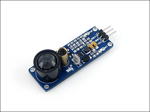
The module contains both a laser transmitter and receiver. The laser beam is transmitted from the gold tube on the module at a particular modulating frequency. The beam will then be reflected off a surface, such as a wall or skirting board, and be picked up by the light sensor lens at the top of the module.
The receiver will only detect light that is modulated at the same frequency as the laser beam, and so does not get affected by visible light. This particular module works best when the reflective surface is between 80 and 120 cm away from the laser transmitter.
When the beam is interrupted and prevented from reflecting back to the receiver, this is detected and the data pin will be triggered. A script monitoring the data pin on the Pi will then do something when it detects this trigger.
This particular device runs from a power supply of between 2.5V and 5.0V. Since our GPIO inputs require 3.3V maximum when a high level is input, we will use the 3.3V supply from our Raspberry Pi to power the device:
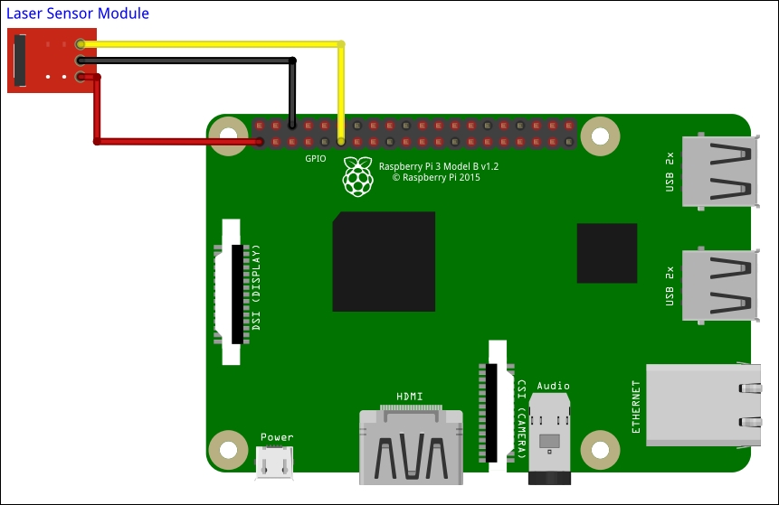
- Connect the included 3-hole connector to the three pins at the bottom of the laser module, with the red wire on the left (the pin marked VCC).
- Referring to the earlier GPIO pin-out diagram, connect the yellow wire to pin 11 of the GPIO connector (labeled D0/GPIO 17).
- Connect the black wire to pin 6 of the GPIO connector (labeled GND/0V).
- Connect the red wire to pin 1 of the GPIO connector (3.3V). The module should now come alive.
- The red LED on the left of the module will come on if the beam is interrupted.
This is what it should look like in reallife:
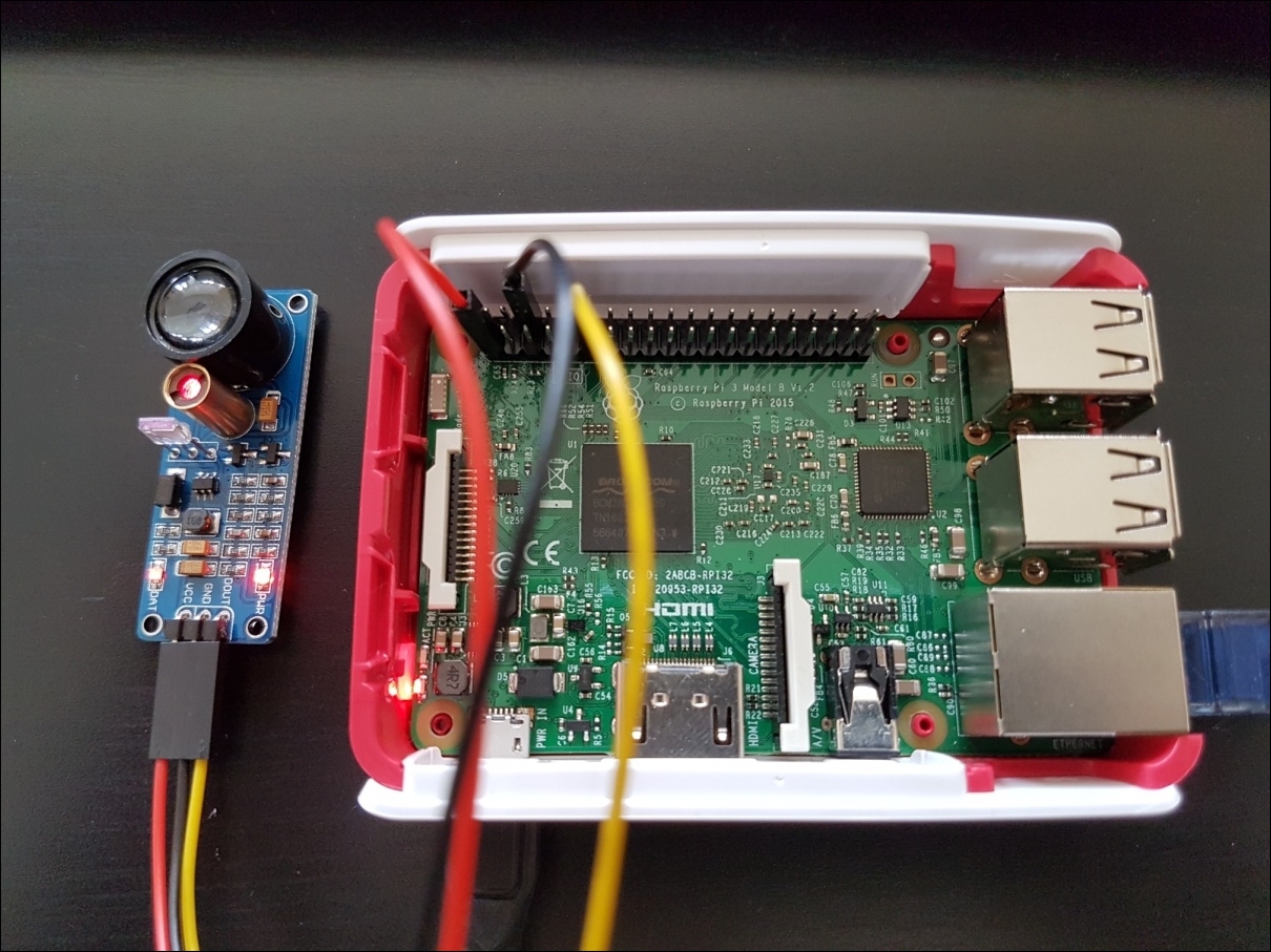 The laser module connected to the Raspberry Pi
Now that we have connected the laser sensor module to our Raspberry Pi, we need to write a little script that will detect when the beam has been broken.
In this project, we've connected our sensor output to D0, which is GPIO17 (refer to the earlier GPIO pin-out diagram). We need to create file access for the pin by entering the following command:
pi@raspberrypi ~ $ sudo echo 17 > /sys/class/gpio/export
And now, set its direction to in:
pi@raspberrypi ~ $ sudo echo in > sys/class/gpio/gpio17/direction
We're now ready to read its value, and we can do this with the following command:
pi@raspberrypi ~ $ sudo cat /sys/class/gpio/gpio17/value
You'll notice that it will have returned 1 (digital high state) if the beam reflection is detected, or a 0 (digital low state) if the beam is interrupted.
We can create a script to poll for the beam state:
#!/bin/bash
sudo echo 17 > /sys/class/gpio/export
sudo echo in > /sys/class/gpio/gpio17/direction

# loop forever
while true
do
  # read the beam state
  BEAM=$(sudo cat /sys/class/gpio/gpio17/value)

  if [ $BEAM == 1 ]; then
    #beam not blocked
    echo "OK"

  else
    #beam was broken
    echo "ALERT"

  fi
done
Code listing for beam-sensor.sh
When you run the script, you should see OK scroll up the screen. Now interrupt the beam using your hand and you should see ALERT scroll up the console screen until you remove your hand.
Don't forget that once we've finished with the GPIO port, it's tidy to remove its file access:
pi@raspberrypi ~ $ sudo echo 17 > /sys/class/gpio/unexport
We've now seen how to easily read a GPIO input; the same wiring principle and script can be used to read other sensors, such as motion detectors or anything else that has an on and off state, and act upon their status.
Our laser trip wire is great for being able to detect when someone walks through a doorway or down a corridor, but what if we wanted to know if people are in a particular area or a whole room?
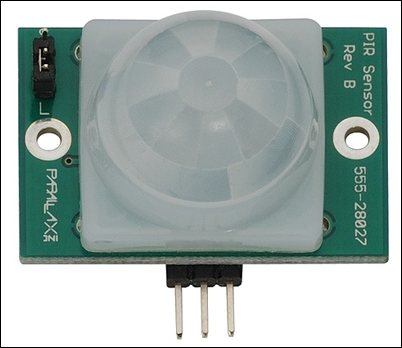
Well, we can with a basic motion sensor, otherwise known as a passive infrared (PIR) detector. These detectors come in a variety of types, and you may have seen them lurking in the corners of rooms, but fundamentally, they all work the same way, by detecting the presence of body heat in relation to the background temperature, within a certain area, and so are commonly used to trigger alarm systems when somebody (or something such as a pet cat) has entered a room.
For the covert surveillance of our private zone, we're going to use a small Parallax PIR Sensor, available from many online Pi-friendly stores such as ModMyPi, Robot Shop, or Adafruit for less than £10 / $15. This little device will detect the presence of enemies within a 10 meter range of it. If you can't obtain one of these types then there are other types that will work just as well, but the wiring might be different to that explained in this project:
As with our laser sensor module, this device also just needs three wires to connect it to the Raspberry Pi. However, they are connected differently on the sensor, as shown below:
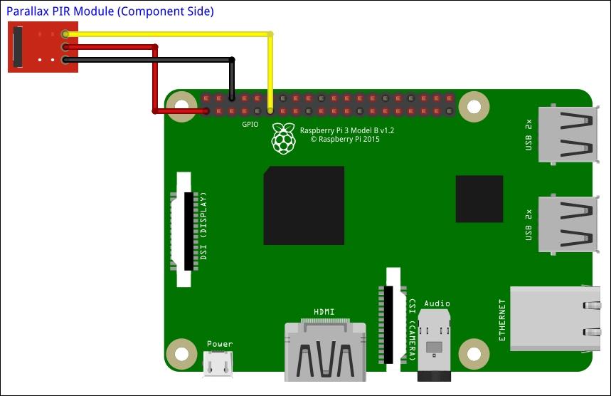
- Referring to the earlier GPIO pin-out diagram, connect the yellow wire to pin 11 of the GPIO connector (labelled D0 /GPIO 17), with the other end connecting to the OUT pin on the PIR module.
- Connect the black wire to pin 6 of the GPIO connector (labelled GND / 0V), with the other end connecting to the GND pin on the PIR module.
- Connect the red wire to pin 1 of the GPIO connector (3.3V), with the other end connecting to the VCC pin on the module. The module should now come alive, and you'll notice the light switching on and off as it detects your movement around it.
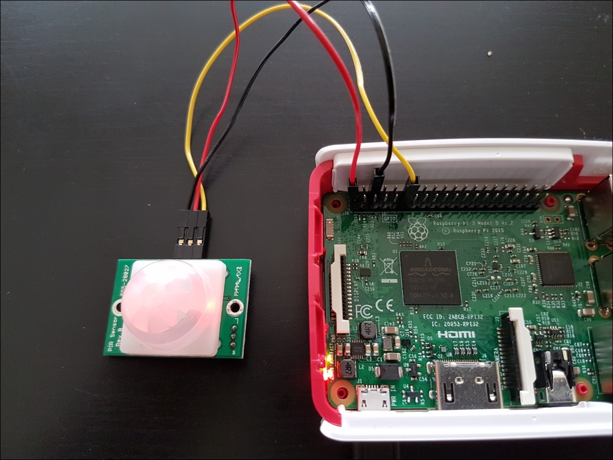
This is what it should look like for real:
The detection script for the PIR motion sensor is similar to the one we created for the laser sensor module in the previous section.
Once again, we've connected our sensor output to D0, which is GPIO17 (refer to the earlier GPIO pin-out diagram). We create file access for the pin by entering the following command:
pi@raspberrypi ~ $ sudo echo 17 > /sys/class/gpio/export
We then set its direction to in:
pi@raspberrypi ~ $ sudo echo in >/sys/class/gpio/gpio17/direction
We're now ready to read its value, and we can do this with the following command:
pi@raspberrypi ~ $ sudo cat /sys/class/gpio/gpio17/value
You'll notice that this time, the PIR module will have returned 1 (digital high state) if the motion is detected, or a 0 (digital low state) if there is no motion detected.
We can modify our previous script to poll for the motion-detected state:
#!/bin/bash
sudo echo 17 > /sys/class/gpio/export
sudo echo in > /sys/class/gpio/gpio17/direction

# loop forever
while true
do
  # read the beam state
  BEAM=$(sudo cat /sys/class/gpio/gpio17/value)

  if [ $BEAM == 0 ]; then
    #no motion detected
    echo "OK"

  else
    #motion was detected
    echo "INTRUDER!"

  fi
done
Code listing for motion-sensor.sh
When you run the script, you should see OK scroll up the screen if everything is nice and still. Now move in front of the PIR's detection area and you should see INTRUDER! scroll up the console screen until you are still again.
Again, don't forget that once we've finished with the GPIO port, we should remove its file access:
pi@raspberrypi ~ $ sudo echo 17 > /sys/class/gpio/unexport