5.4. NUMERICAL FINITE-DIFFERENCE METHODS FOR UNSTEADY-STATE CONDUCTION
5.4A. Unsteady-State Conduction in a Slab
1. Introduction
As discussed in previous sections of this chapter, the partial differential equations for unsteady-state conduction in various simple geometries can be solved analytically if the boundary conditions are constant at T = T1 with time. Also, in the solutions the initial profile of the temperature at t = 0 is uniform at T = T0. The unsteady-state charts used also have these same boundary conditions and initial condition. However, when the boundary conditions are not constant with time and/or the initial conditions are not constant with position, numerical methods must be used.
Numerical calculation methods for unsteady-state heat conduction are similar to numerical methods for steady state discussed in Section 4.15. The solid is subdivided into sections or slabs of equal length and a fictitious node is placed at the center of each section. Then a heat balance is made for each node. This method differs from the steady-state method in that we have heat accumulation in a node for unsteady-state conduction. The methods are well suited for a spreadsheet calculation.
2. Equations for a slab
The unsteady-state equation for conduction in the x direction in a slab is
Equation 5.1-10
![]()
This can be set up for a numerical solution by expressing each partial derivative as an actual finite difference in ΔT, Δt, and Δx. However, an alternative method will be used to derive the final result by making a heat balance. Figure 5.4-1 shows a slab centered at position n, represented by the shaded area. The slab has a width of Δx m and a cross-sectional area of A m2. The node at position n having a temperature of Tn is placed at the center of the shaded section; this node represents the total mass and heat capacity of the section or slab. Each node is imagined to be connected to the adjacent node by a fictitious, small conducting rod. (See Fig. 4.15-3 for an example.)
Figure 5.4-1. Unsteady-state conduction in a slab.

The figure shows the temperature profile at a given instant of time t s. Making a heat balance on this node or slab, the rate of heat in – the rate of heat out = the rate of heat accumulation in Δt s:
Equation 5.4-1
![]()
where tTn is the temperature at point n at time t and t+ΔtTn is the temperature at point n at time t + 1 Δt later. Rearranging and solving for t+ΔtTn,
Equation 5.4-2
![]()
where
Equation 5.4-3
![]()
Note that in Eq. (5.4-2) the temperature t+ΔtTn at position or node n and at a new time t + Δt is calculated from the three points which are known at time t, the starting time. This is called the explicit method, because the temperature at a new time can be calculated explicitly from the temperatures at the previous time. In this method the calculation proceeds directly from one time increment to the next until the final temperature distribution is calculated at the desired final time. Of course, the temperature distribution at the initial time and the boundary conditions must be known.
Once the value of Δx has been selected, then from Eq. (5.4-3) a value of M or the time increment Δt may be picked. For a given value of M, smaller values of Δx mean smaller values of Δt. The value of M must be as follows:
Equation 5.4-4
![]()
If M is less than 2, the second law of thermodynamics is violated. It also can be shown that for stability and convergence of the finite-difference solution, M must be ≥2.
Stability means the errors in the solution do not grow exponentially as the solution proceeds but damp out. Convergence means that the solution of the difference equation approaches the exact solution of the partial differential equation as Δt and Δx go to zero with M fixed. Using smaller sizes of Δt and Δx increases the accuracy in general but greatly increases the number of calculations required. Hence, a digital computer is often ideally suited for this type of calculation using a spreadsheet.
3. Simplified Schmidt method for a slab
If the value of M = 2, then a great simplification of Eq. (5.4-2) occurs, giving the Schmidt method:
Equation 5.4-5
![]()
This means that when a time 1 Δt has elapsed, the new temperature at a given point n at t + Δt is the arithmetic average of the temperatures at the two adjacent nodes n + 1 and n − 1 at the original time t.
5.4B. Boundary Conditions for Numerical Method for a Slab
1. Convection at the boundary
For the case where there is a finite convective resistance at the boundary and the temperature of the environment or fluid outside is suddenly changed to Ta, we can derive the following for a slab. Referring to Fig. 5.4-1, we make a heat balance on the outside half-element. The rate of heat in by convection − the rate of heat out by conduction = the rate of heat accumulations in Δt s:
Equation 5.4-6
![]()
where tT1.25 is the temperature at the midpoint of the 0.5 Δx outside slab. As an approximation, the temperature T1 at the surface can be used to replace that of T1.25. Rearranging,
Equation 5.4-7
![]()
where
Equation 5.4-8
![]()
Note that the value of M must be such that
Equation 5.4-9
![]()
2. Insulated boundary condition
In the case for the boundary condition where the rear face is insulated, a heat balance is made on the rear ![]() slab just as on the front
slab just as on the front ![]() slab in Fig. 5.4-1. The resulting equation is the same as Eqs. (5.4-6) and (5.4-7), but h = 0 or N = 0 and tTf−1 = tTf+1 because of symmetry.
slab in Fig. 5.4-1. The resulting equation is the same as Eqs. (5.4-6) and (5.4-7), but h = 0 or N = 0 and tTf−1 = tTf+1 because of symmetry.
Equation 5.4-10
![]()
3. Alternative convective condition
To use the equations above for a given problem, the same values of M, Δx, and Δt must be used. If N gets too large, so that M may be inconveniently too large, another form of Eq. (5.4-7) can be derived. By neglecting the heat accumulation in the front half-slab in Eq. (5.4-6),
Equation 5.4-11
![]()
Here the value of M is not restricted by the N value. This approximation works fairly well when a large number of increments in Δx are used so that the amount of heat neglected is small compared to the total.
4. Procedures for use of initial boundary temperature
When the temperature of the environment outside is suddenly changed to Ta, the following procedures should be used.
When M = 2 and a hand calculation of a limited number of increments is used, a special procedure should be used in Eqs. (5.4-5) and (5.4-7) or (5.4-11). For the first time increment, one should use an average value for 1Ta of (Ta + 0T1)/2, where 0T1 is the initial temperature at point 1. For all succeeding Δt values, the value of Ta should be used (D1, K1). This special procedure for determining the value of Ta to use for the first time increment increases the accuracy of the numerical method, especially after a few time intervals. If Ta varies with time t, a new value can be used for each Δt interval.
When M = 2 and many time increments are used with a digital computer, this special procedure is not needed, and the same value of Ta is used for all time increments.
When M = 3 or more and a hand calculation of a limited number of increments or a digital-computer calculation of many increments is used, only one value of Ta is used for all time increments. Note that when M = 3 or more, many more calculations are needed compared to the case for M = 2. The most accurate results are obtained when M = 4, which is the preferred method, with slightly less accurate results for M = 3 (D1, K1, K2).
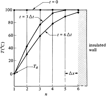
EXAMPLE 5.4-1. Unsteady-State Conduction and the Schmidt Numerical MethodA slab of material 1.00 m thick is at a uniform temperature of 100°C. The front surface is suddenly exposed to a constant environmental temperature of 0°C. The convective resistance is zero (h = ∞). The back surface of the slab is insulated. The thermal diffusivity α = 2.00 × 10⁻⁵ m2/s. Using five slices each 0.20 m thick and the Schmidt numerical method with M = 2.0, calculate the temperature profile at t = 6000 s. Use the special procedure for the first time increment. Solution: Figure 5.4-2 shows the temperature profile at t = 0 and the environmental temperature of Tα = 0°C with five slices used. For the Schmidt method, M = 2. Substituting into Eq. (5.4-3) with α = 2.00 × 10⁻⁵ and Δx = 0.20 and solving for Δt, Equation 5.4-3
Figure 5.4-2. Temperature for numerical method, Example 5.4-1.
This means that (6000 s)/(1000 s/increment), or six time increments, must be used to reach 6000 s. For the front surface, where n = 1, the temperature 1Ta to use for the first Δt time increment, as stated previously, is Equation 5.4-12
where 0T1 is the initial temperature at point 1. For the remaining time increments, Equation 5.4-13
To calculate the temperatures for all time increments for the slabs n = 2 to 5, using Eq. (5.4-5), Equation 5.4-14
For the insulated end for all time increments at n = 6, substituting M = 2 and f = 6 into Eq. (5.4-10), Equation 5.4-15
For the first time increment of t + Δt, and calculating the temperature at n = 1 by Eq. (5.4-12),
For n = 2, using Eq. (5.4-14),
Continuing for n = 3, 4, 5, we have
For n = 6, using Eq. (5.4-15),
For 2 Δt, using Eq. (5.4-13) for n = 1, and continuing for n = 2 to 6, using Eqs. (5.4-14) and (5.4-15),
For 3 Δt,
For 4 Δt,
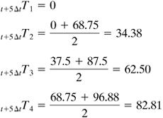
For 5 Δt,
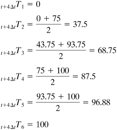
For 6 Δt (final time),
The temperature profiles for 3 Δt increments and the final time of 6 Δt increments are plotted in Fig. 5.4-2. This example shows how a hand calculation can be done. To increase the accuracy, more slab increments and more time increments are required. This, then, is ideally suited for computation using a spreadsheet with a computer. |
EXAMPLE 5.4-2. Unsteady-State Conduction Using the Digital ComputerRepeat Example 5.4-1 using the digital computer. Use Δx = 0.05 m. Write the spreadsheet program and compare the final temperatures with Example 5.4-1. Use the explicit method of Schmidt for M = 2. Although not needed for many time increments using the digital computer, use the special procedure for the value of 1Ta for the first time increment. Thus a direct comparison can be made with Example 5.4-1 of the effect of the number of increments on the results. Solution: The number of slabs to use is 1.00 m/(0.05 m/slab) or 20 slabs. Substituting into Eq. (5.4-3) with α = 2.00 × 10⁻⁵ m2/s, Δx = 0.05 m, and M = 2, and solving for Δt,
Hence, (6000/62.5) = 96 time increments to be used. The value of n goes from n = 1 to 21. The equations to use to calculate the temperatures are again Eqs. (5.4-12)– (5.4-15). However, the only differences are that in Eq. (5.4-14) n goes from 2 to 20, and in Eq. (5.4-15) n = 21, so that t+ΔtT21 = tT20. The spreadsheet for these equations is easily written and is left up to the reader. The results are tabulated in Table 5.4-1 for comparison with Example 5.4-1, where only five slices were used. The table shows that the results for five slices are reasonably close to those for 20 slices, with values in both cases deviating by 2% or less from each other.
| |||||||||||||||||||||||||||||||||||||||||||||
As a rule-of-thumb guide for hand calculations, using a minimum of five slices and at least 8–10 time increments should give sufficient accuracy for most purposes. Only when very high accuracy is desired or several cases are to be solved is it desirable to solve the problem using a spreadsheet calculation with a computer.
EXAMPLE 5.4-3. Unsteady-State Conduction with Convective Boundary ConditionUse the same conditions as Example 5.4-1, but a convective coefficient of h = 25.0 W/m2 · K is now present at the surface. The thermal conductivity k = 10.0 W/m · K. Solution: Equations (5.4-7) and (5.4-8) can be used for convection at the surface. From Eq. (5.4-8), N = hΔ×/k = 25.0(0.20)/10.0 = 0.50. Then 2N + 2 = 2(0.50) + 2 = 3.0. However, by Eq. (5.4-9), the value of M must be equal to or greater than 2N + 2. This means that a value of M = 2 cannot be used. We will select the preferred method where M = 4.0. [Another, less accurate alternative is to use Eq. (5.4-11) for convection, and then the value of M is not restricted by the N value.] Substituting into Eq. (5.4-3) and solving for Δt,
Hence, 6000/500 = 12 time increments must be used. For the first Δt time increment and for all time increments, the value of the environmental temperature Ta to use is Ta = 0°C since M > 3. For convection at the node or point n = 1 we use Eq. (5.4-7), where M = 4 and N = 0.50: Equation 5.4-16
For n = 2, 3, 4, 5, we use Eq. (5.4-2), Equation 5.4-17
For n = 6 (insulated boundary), we use Eq. (5.4-10) and f = 6. Equation 5.4-18
For 1 Δt, for the first time increment of t + Δt, Ta = 0. Using Eq. (5.4-16) to calculate the temperature at node 1,
For n = 2, 3, 4, 5, using Eq. (5.4-17),
Also, in a similar calculation, T3, T4, and T5 = 100.0. For n = 6, using Eq. (5.4-18), T6 = 100.0. For 2 Δt, Ta = 0. Using Eq. (5.4-16),
Using Eq. (5.4-17) for n = 2, 3, 4, 5,
Also, T4 and T5 = 100.0. For n = 6, using Eq. (5.4-18), T6 = 100.0. For 3 Δt, Ta = 0. Using Eq. (5.4-16),
Using Eq. (5.4-17) for n = 2, 3, 4, 5,
Also, T5 = 100.0 and T6 = 100.0. In a similar manner the calculations can be continued for the remaining time until a total of 12 Δt increments have been used. |
5.4C. Other Numerical Methods for Unsteady-State Conduction
1. Unsteady-state conduction in a cylinder
In deriving the numerical equations for unsteady-state conduction in a flat slab, the cross-sectional area was constant throughout. In a cylinder it changes radially. To derive the equation for a cylinder, Fig. 5.4-3 is used, where the cylinder is divided into concentric hollow cylinders whose walls are Δ× m thick. Assuming a cylinder 1 m long and making a heat balance on the slab at point n, the rate of heat in − rate of heat out = rate of heat accumulation:
Equation 5.4-19

Figure 5.4-3. Unsteady-state conduction in a cylinder.

Rearranging, the final equation is
Equation 5.4-20
![]()
where M = (Δ×)2/(α Δt) as before. Also, at the center where n = 0,
Equation 5.4-21
![]()
To use Equations (5.4-20) and (5.4-21),
Equation 5.4-22
![]()
Equations for convection at the outer surface of the cylinder have been derived (D1). If the heat capacity of the outer half-slab is neglected,
Equation 5.4-23

where Tn is the temperature at the surface and Tn−1 the temperature at a position in the solid 1 Δ× below the surface.
Equations for numerical methods for two-dimensional unsteady-state conduction have been derived and are available in a number of references (D1, K2).
2. Unsteady-state conduction and implicit numerical method
In some practical problems the restrictions imposed on the value M ≥ 2 by stability requirements may prove inconvenient.Also, to minimize the stability problems, implicit methods using different finite-difference formulas have been developed.An important one of these formulas is the Crank–Nicolson method, which will be considered here.
In deriving Eqs. (5.4-1) and (5.4-2), the rate at which heat entered the slab in Fig. 5.4-1 was taken to be the rate at time t:
Equation 5.4-24
![]()
It was then assumed that this rate could be used during the whole interval from t to t + Δt. This is an approximation, however since the rate changes during this Δt interval. A better value would be the average value of the rate at t and at t + Δt, or
Equation 5.4-25
![]()
For the heat leaving, a similar type of average is used. The final equation is
Equation 5.4-26
![]()
This means that now a new value of t+ΔtTn cannot be calculated only from values at time t, as in Eq. (5.4-2), but that all the new values of T at t + Δt at all points must be calculated simultaneously. To do this, an equation similar to Eq. (5.4-26) is written for each of the internal points. Each of these equations and the boundary equations are linear algebraic equations. These then can be solved simultaneously by the standard methods, such as the Gauss–Seidel iteration technique, matrix inversion technique, and so on (G1, K1).
An important advantage of Eq. (5.4-26) is that the stability and convergence criteria are satisfied for all positive values of M. This means that M can have values less than 2.0. A disadvantage of the implicit method is the larger number of calculations needed for each time step. Explicit methods are simpler to use, but because of stability considerations, especially in complex situations, implicit methods are often preferred.


