Alright! Let's start exploring the visual material system provided in UE4 that affords us the ability to create amazing and interesting rendering techniques without writing a single line of code! By the end of this chapter we will have created two materials that we will apply to the boss so that it looks like a sinister robotic powerhouse.
UE4 materials are a visual node-based scripting system that is used to create rendering techniques to be applied to object surfaces. This system massively simplifies the process of developing visually impressive and complex shaders by removing the barrier to entry that is low-level shader programming! However if you wish to add to the systems vast feature set and shader library, the system is also extensible by allowing developers to write their own material expressions via shaders if need be.
Each node in a material graph represents a piece of shading code in some manner, they are known as material expressions. This means that as you increase the number of nodes in a material, the number of shaders required for compilation increases. Therefore, when creating materials in UE4 you have balance efficiency and visual output.
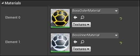
We are going to be leveraging this system to create two materials. One for the boss's outer shell and one for the boss's inner shell. By the end of this chapter you will be comfortable creating basic and intermediate-level materials. We will be working with masks, emissive coloring, color animation as a function of time, and normal maps.
UE4 materials support Physically Based Rendering (PBR) for short. This is a new rendering technique within the games industry. Traditionally, when rendering objects, you would describe the lighting detail of the object specifically, per object. As in, this object is this color, this texture, and has this light affecting it. This is a very costly way to render complicated techniques. PBR is a technique where instead of describing the materials lighting and texture properties in detail, we will instead describe the material in a physical sense. If this confuses you, think of it this way. We are now informing the rendering system of how this material appears without any consideration of light or environment.
For example, if I were to describe concrete, I would say it is a rough, matt material that is not shiny at all. So if I were to create an object that requires a concrete material, I would inform the engine of the same information. Unreal Engine's rendering system is set up so that we can describe materials in this way, and its robust deferred shading model will handle rendering the material given different lighting and environmental factors.
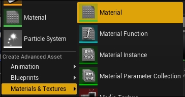
Ok, let's create our first material and have a look at the material editor! This editor is fairly unique as there is still a graph within which you can plot and connect nodes, but this time there is no execution path. There is simply a large node that takes in multiple inputs for each element of the surface's properties. For every connected element to this final material node, there will be a series of nodes that must be compiled. Navigate to the content browser of your level editor and create a new material by right-clicking and selecting Material from the Basic Assets list or Materials & Textures | Material.
Call this material BossOuterMaterial. This will be the material we use to render the outer shell of the BossMesh. This editor features 6 panels. They are Toolbar, Graph, Viewport, Details, Stats, and Palette.
The Toolbar panel of the material editor boasts 12 buttons that we can use to help with our material development pipeline. They are as follows:
- Save: Let's you save the current material.
- Find in CB: Allows you to find any texture or asset referenced in the material from within the Content Browser.
- Apply: Allows you to apply the changes you just made to the current material without saving, this allows you to preview in editor and in viewport, material changes without saving those changes.
- Search: Search within the graph for a given node or comment.
- Home: Shifts the graph view back to the main material node.
- Clean Up: Cleans any unused material expressions from within the graph.
- Connectors: Toggleable option that will show or hide any unused connectors (lines between pins).
- Live Preview: Toggleable option that when on, will update the viewport with any material changes as they happen. Having this on will enact a runtime cost when adding nodes to the graph, potentially slowing usability of the material editor.
- Live Nodes: Toggleable option that when on, will update node previews as the graph is edited, same cost as detailed previously.
- Live Update: Toggleable option that sets all nodes to live update as edits are made, same cost as detailed previously.
- Stats: Shows the runtime statistics of the material in the Stats panel.
- Mobile Stats: Shows the runtime statistics of the material if it were run on a mobile in the Stats panel.
The Viewport in the material editor is used to preview the material that is being created when applied to a preview mesh. The viewport boasts some toggleable options that affect the preview of the material. They appear as follows:
- Dropdown: Provides options that show stats such as frame per second and allow adjustments to field of view.
- Perspective: Lets you select which perspective you would like to view the preview mesh with.
- Lit: Lets you change which channel of the deferred rendering system is being used for the preview. This functions in the same way as the option provided in the Level Editor viewport.
- Show: Provides toggable options for showing things such as statistics, background, and grid.
The viewport also allows you to change which mesh is being used to preview the material via the following buttons:
The buttons from left to right will change the preview mesh to a cylinder, sphere, plane, box, and custom mesh. The button highlighted is the custom mesh button. To use this option, you must first have a mesh selected in the Content browser. Do this now by selecting BossMesh from within the Content browser and pressing the teapot button. This will change the Viewport preview mesh to match this:
This is very useful for us, as it means we can preview how the material will look when already applied to the boss mesh!
The Graph panel for the material editor is the canvas with which you will create all of your materials. The nodes that we create in this graph are known as material expressions. They are instructions that will be carried out during material execution (usually at runtime). It is with these expressions that we can instruct how the material will behave and drive the output of the technique.
Every material will have some version of the following expression by default, as follows:
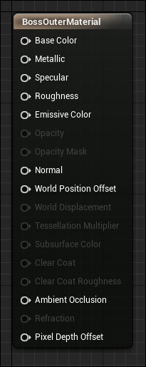
This is the main material expression. It is with this expression that we provide all color/material calculations that drive the material's final appearance. It is important to note that when we provide inputs to this expression, what we are effectively saying is for each pixel of this surface to be drawn, I want these calculations to take place. This means we can have explicit control over each pixel's physical appearance of a given surface, this also means that we can make our materials very expensive, very quickly. Usually these per-pixel calculations require in-depth logics to determine how to color each pixel based off of the inputs we provide. Thankfully the material system automates this process by doing much of the per-pixel calculations automatically behind the scenes for us. All we have to do is provide the correct textures, normal maps, and masks.
Pins within this expression will be disabled and enabled depending on the type of material that we are working with and the blend/shader properties specified in the Details panel for this expression. The previous arrangement is for a surface material type with default properties, which is perfect for us as we are trying to render an object surface. As UE4 boasts a PBR-supported material system, each pin provided is an element of the surface's physical properties. The pins are responsible for the following:
- Basic Color: The unedited base color of the surface. This is what was known as the diffuse channel for an object. The color provided to this pin should be the color of the surface before lighting and surface properties are considered
- Metallic: This parameter effects how metallic the surface will appear when lit. The more metallic a material looks, the more the surface color and reflection will be modified to look more metal-like, imagine a slightly old copper pot. Non-metals have a metallic value of 0 where metals have a metallic value of 1.
- Specular: This parameter affects how intensely reflections will shine, however this parameter is considered deprecated and it is recommended to use roughness instead and leave this as a default value of 0.5.
- Roughness: This parameter literally effects how rough a surface appears. A rougher material will scatter reflected light in more directions than a smooth material. This affects how blurry or sharp a surface's reflection is. Completely smooth is a value of zero where fully mat is a value of one.
- Emissive Color: This parameter drives any surface color values that you wish to glow as they will be emitting light. Ideally you would create this effect with a mask texture, the result is a clear glow area. Note that emissive color does not cast light on other objects, nor will shadows be generated.
- Opacity: Opacity is used when using a translucent blend mode. This allows you to specify a value that affects how transparent the surface is. Zero being fully transparent and one being fully opaque.
- Opacity Mask: Similar to Opacity however an opacity mask does not support any values between zero and one. This means a surface can either be fully transparent or fully opaque. You can set the threshold at which point the material will swap from opaque to transparent, for example 0.6 in the Details panel.
- Normal: A surface normal is a directional vector that can be used to calculate how any given pixel will be lit based off of the nearest normal. A normal is made up of three floats, therefore a normal can be represented by a color value. Because of this, specialized textures can be made to represent the normal of an object. This is known as a normal map. With this pin you can provide the surface normal map for the object.
- World Position Offset: This pin allows you to provide physical offsets for the vertices in world space. This allows us to create techniques that morph and adjust the shape of a rendered mesh.
- World Displacement: Works in the same way as world position offset but utilizes tessellation as opposed to the base vertices of the mesh. This allows for more detailed displacements.
- Tessellation Multiplier: Controls the amount of tessellation along a surface, allowing more detail to be added when needed. For this and world displacement to work, the tessellation property must be something other than none.
- Subsurface Color: This input allows you to add a color to your material to simulate shifts in color when light passes through the surface. Much like when light passes through a human character's ear or nose. For this input to be enabled, the subsurface shading model must be enabled in the material properties via the Details panel.
- Ambient Occlusion: This pin helps simulate self-shadowing within the crevices of a surface. Generally, this will be connected to a pre-baked AO map.
- Refraction: This input takes in a texture or value that simulates the index of refraction of the surface. This is useful for things such as glass and water, which refract light that passes through them.
- Clear Coat: The clear coat shading model can be used to simulate multilayer materials that have a thin translucent layer of film over the surface of the material. This is very effective for rendering materials such as acrylic, multi-tone car paint, and oils. Again this setting must be enabled within the properties of the material. Zero will use no clear coat coloring, one will use the full clear coat value.
The Details panel that is featured in the material editor is where we can find all of the properties for any given material expression. It is also here that you will be able to select the material properties such as shading, blending, and tessellation models for the material as a whole, if no expression or the main expression node is selected. The default properties for this material are as follows:
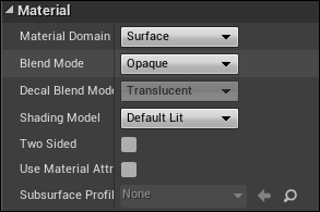
Here we have specified that this is a Surface type material using the Opaque blend mode with the Default Lit Shading Model. If you were to change any of these settings, you would see various pins enable and disable in the main material expression node.
It is with this panel that you can see any diagnostic output for the material. Here we can get output information about the material's current calculation cost, instruction count, and number of texture samples.
The palette is one of the most important panels in the material editor, it is here where you can find all of the material expressions that can be used within the graph. The palette functions in the same way as the palette featured in blueprint and allows for the keyword searching of different expressions.
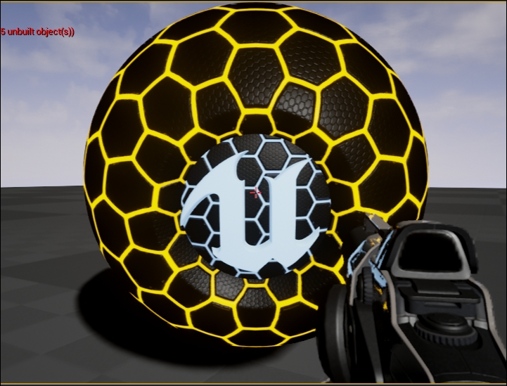
Ok, let's start working with the material editor by creating our boss's outer shell! At first we are going to try to achieve something that looks similar to this:
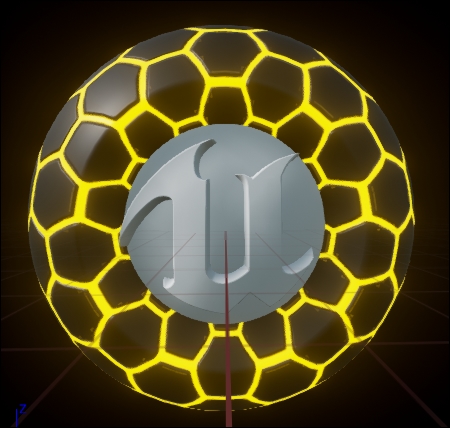
This is simply a material that has a hexagonal emissive pattern, an applied normal map, and a default base color. We will continue to develop this material so that we can achieve the look in the previous picture of the boss. Let's start by summoning our first material expression.
Right-click in a blank area of the material graph or use the palette search for the expression VectorParameter. This will summon the following node:
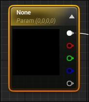
This VectorParameter expression allows us to create a four float RGBA value that we can use as a color sample within the material. As you can see, there are five available pins. The top-most pin is the output four floats, or the color value as a whole. The other four pins are the different color channels. These pins represent the Red, Green, Blue, and Alpha channels in that order. Color channels are a very core concept of rendering theory as we can split maps and masks up into their individual color components. We do this so we can pack more data into one color map. This will become readily apparent when we start to work with masks and other texture types.
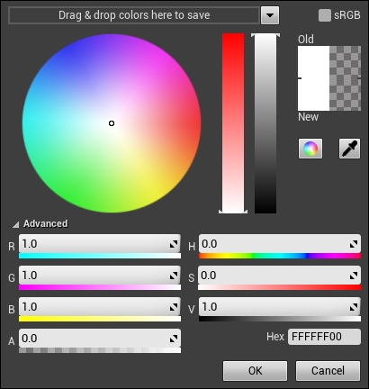
With this expression selected, address the Details panel. The panel will have updated with the properties of this material expression. Here we can set the default value for the vector parameter, which appears in the form of a color bar. Clicking on this color bar lets us use the Unreal color picker to choose a color for the parameter. Underneath this we have the expressions Name and Group. These do two things for us. The first is they provide us with a unique and hopefully contextual name we can use for the expression. The second is they allow us to get access to this parameter from blueprint and code. This process will be detailed in the next chapter.
Name this node BaseColor now and change the base color to pure white by double-clicking on the Color Bar and setting the picker to these values:
We will be changing this color later so that it looks more visually appropriate, but for now I have chosen white to demonstrate a drastic change from the default base color value of the main material expression node. Now drag a connection from the top-most pin on the BaseColor node and connect it to the BossOuterMaterial expression, like so:
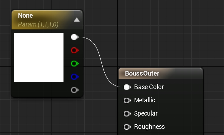
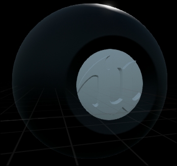
You will have noticed that the preview mesh within the viewport will have updated to appear as follows:
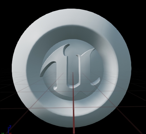
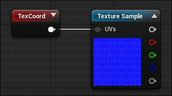
With our temporary base color applied we can add a normal map to the material. As stated previously, normal maps provide a cheap way to add high amounts of detail to an object's surface. Thankfully all of the maps we will be using in this chapter are provided with the starter content that we created the project with. Summon our next material expression Texture Sample. This will summon the following node:
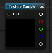
As you can see, this expression looks very similar to that of the Vector Parameter expression we created earlier. This expression still boasts the five output pins, one for the whole texture, the other for the channels of the texture, however this node also takes an input pin called UVs. UVs are a way for us to inform the material what part of the texture we would like to apply to this given vertex or mesh pixel. UVs are a two float vector, one parameter specifies the X value of the texture and the other the Y. Combined, they will point to a specific point within a texture that we will sample for pixel calculations. This will be described in more detail soon, for now, select this node and address the Details panel.
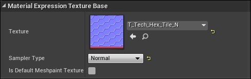
Here we can see properties that let us modify the literal sample states for the texture and we can also see it is here where we can specify the texture we wish to use. Click on the dropdown next to the Texture property, search for and apply the T_Tech_Hex_Tile_N map. This is the normal map we are going to use. With this texture applied, the details panel will update to appear as follows:
If you double-click on the texture thumbnail it will take you to the UE4 texture editor. This editor lets us edit the various properties of the texture as well as view each channel (RGBA) of the texture independently. We will expand on this later. Navigate back to the material editor. We are about to connect our normal map to the main expression. Connect the top-most output pin of the Texture Sample node to the Normal input pin of the main material expression, like so:
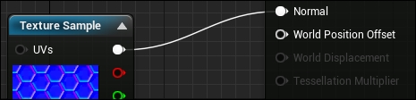
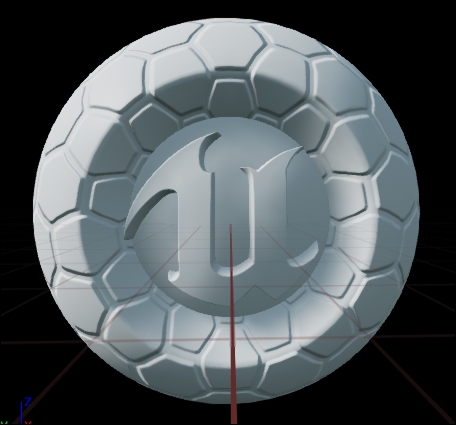
This now means that, for every pixel of the surface, this material expression will provide normal information so that the pixels can be lit properly. This results in a more detailed surface as can be seen in the preview window once the material updates.
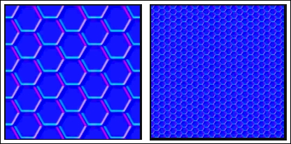
Ok, now that we have our base color and our normal map detail, let's work on the glowing hexagonal pattern. Summon another Texture Sample node but this time assign the T_Tech_Hex_Tile_M texture and open it in the Texture Editor by double-clicking the Thumbnail. The texture should appear like this:
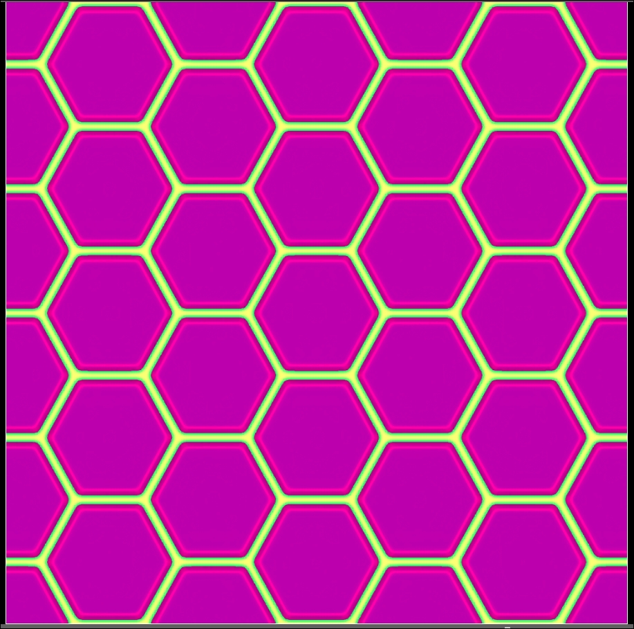
You will also notice a small View button in the top left-hand side of the Viewport panel of this editor. Clicking this button will show you the various view options available for this texture, like so:
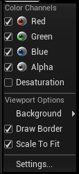
As you can see, all of the color channels are currently ticked. These are toggleable options that allow us to view the various channels in the texture, alone or combined. Each channel for this texture appears as so:
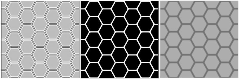
With the Red channel on the left, the Green channel in the middle, and the Blue channel on the right, as you can see, the green channel provides us with a white and black texture, where the regions within the hexagons will have a value of zero and the borders of the hexagons will have a value of one. This is very important, as this channel of this texture will act as the mask for our emissive glow!
In short, what we are going to do is take the color value of this mask and multiply that by a default emissive color. As the value from this mask will either be zero or one, the result of the multiplication will be a full emissive color or no emissive color. When we plug the result of this calculation into the emissive color pin of the main material expression, we will have an emissive glow on the object surface in the form of the pattern shown in the Green channel of this mask.
Before we continue, it is important to note that in this texture editor we can change some of the color properties of the mask and texture via the details panel. We can also see some statistics for the texture such as Size, Format, and number of mips. We will not be changing any of these values within the scope of this chapter. Let's set up the expressions for this now. Navigate back to the material editor.
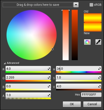
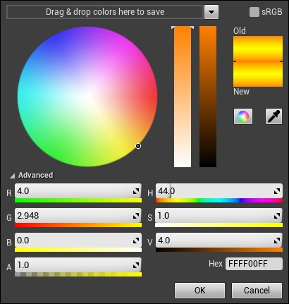
Underneath the Texture Sample expression we just created, summon another VectorParameter. This time, set the name to be Emissive Color 01 and set the color picker to these values:
Next, summon a Multiply expression. This is a simple node that takes in two pins and outputs one. Plug the Green channel of the TextureSample Mask into the A pin and the output pin of Emissive Color 01 node into the B pin. Plug the output pin of the multiply node into the Emissive Color pin of the final material expression. This will appear like so:
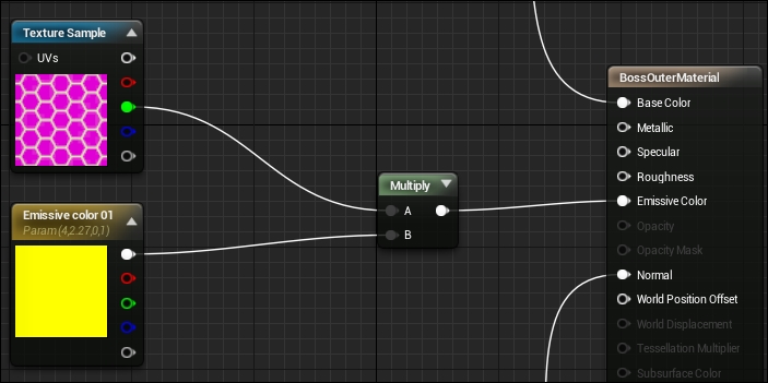
The last thing we need to do is set our BaseColor value back to black so that our emissive color really pops. Do this now. Your final graph should look similar to this:
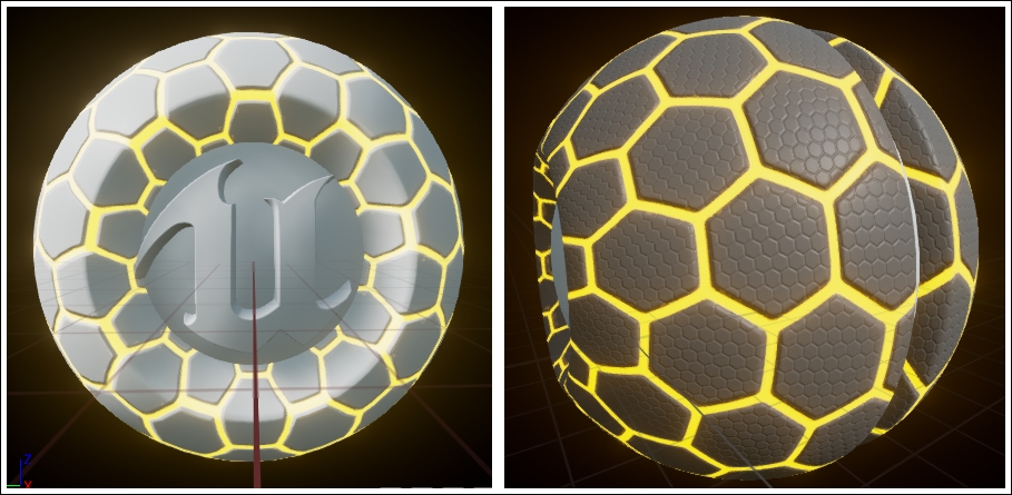
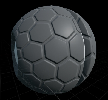
And your material preview should look similar to this (right is with a white base color, left is with black):
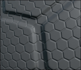
Now that we have our basic material coloring set up, we can now add detail to the material. We are going to be adding sub detail within each of the hexagons and making our emissive glow pulse as if there was some unknown power contained within our boss. The output we are looking for will appear like this:
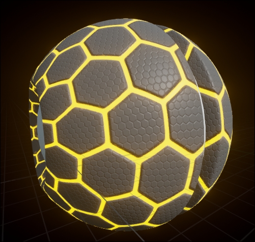
As you can see, we have added more detail to the interior of the hexagons. In the previous image I changed the base color to a lighter value so the details would be more obvious.
Ok, to achieve the detail we want, we are going to have to work with our normal maps some more. As mentioned previously, UVs drive how a given pixel is mapped to a mesh. Because of this we can adjust a UV property called UV tiling, which will affect how many times that texture repeats on a given surface. For example, with this normal map in question, the image on the left is a map with UV tiling set to 1 for both U and V, and the image on the right is a map with UV tiling set to 4, in other words the map on the right will repeat four times in the space, the first will only repeat once:
UVs are known by another name as well. Texture coordinates. This is because a UV is also the XY location to look at on a texture. If a UV scale is 1, U (0.5) and V (0.5) will give you the pixel in the very middle of the texture, whereas, U and V values of zero or one will give you the top left-hand and bottom right-hand corners respectively. This means we are able to index any location on a texture via UVs.
What we are going to be doing is taking normals from two different Texture Samples of the same normal map, but each with their own UV tiling. We are then going to be blending these together to create the detail effect we desire. The first thing we need to do is disable the emissive glow so we can better see our detail. Do this now so the material appears as so in the preview (note I have rotated the preview mesh for clarity):
Now, navigate to the area of the graph where we sample our normal map. Underneath this, create another Texture Sample expression with the same T_Tech_Hex_Tile_N texture applied. We are now going to be plugging something into the UV pin of this node. Summon a new expression called TextureCoordinate. This will summon a small red node called TexCoord. With this node selected, address the Details panel where you will see the properties of this texture coordinate node. Change the UTiling and VTiling properties to 8. Then plug the output of this TexCoord node into the input pin of the second Texture Sample we just created. So far everything should look like this:
Now, before we blend our two normal maps together, we need to do some more masking operations. That is because if we were to blend our normal maps together now, we would get detail in the areas of our surface where the emissive glow is supposed to be. This would appear like so:
This could lead to some undesirable effects. Unfortunately, unlike our emissive mask, we cannot perform a straight multiply with the zero value of the mask. When working with normal maps (0, 0, 0) is not the color value of flat. We need to use (0, 0, 1) or 1, or on the Blue channel. This is because the RGB values of a color are converted to the XYZ values of a vector. Thus, with 1 in the B channel, we have a normal that is of 1 length in only the Z component, therefore the normal is pointing straight up and no detail will be added. We need to instead interpolate between our desired normal detail and this flat blue value based off of the value held in the mask. This will mean that when the mask value returns zero (inside the hexagon), we will use the full detail normal map, and when it returns 1 (inside the borders), we will use flat blue.
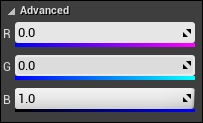
Underneath the Texture Sample we just created, summon a new expression. This one is called a Constant3Vector. This functions in a very similar way to that of our VectorParameter expressions, however these constants are not editable or modifiable from outside of the material editor, thus the name constant. We are also unable to provide these expressions with unique names. Set the color values of this constant in the color picker to appear as follows:
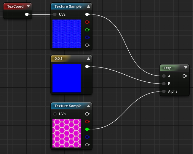
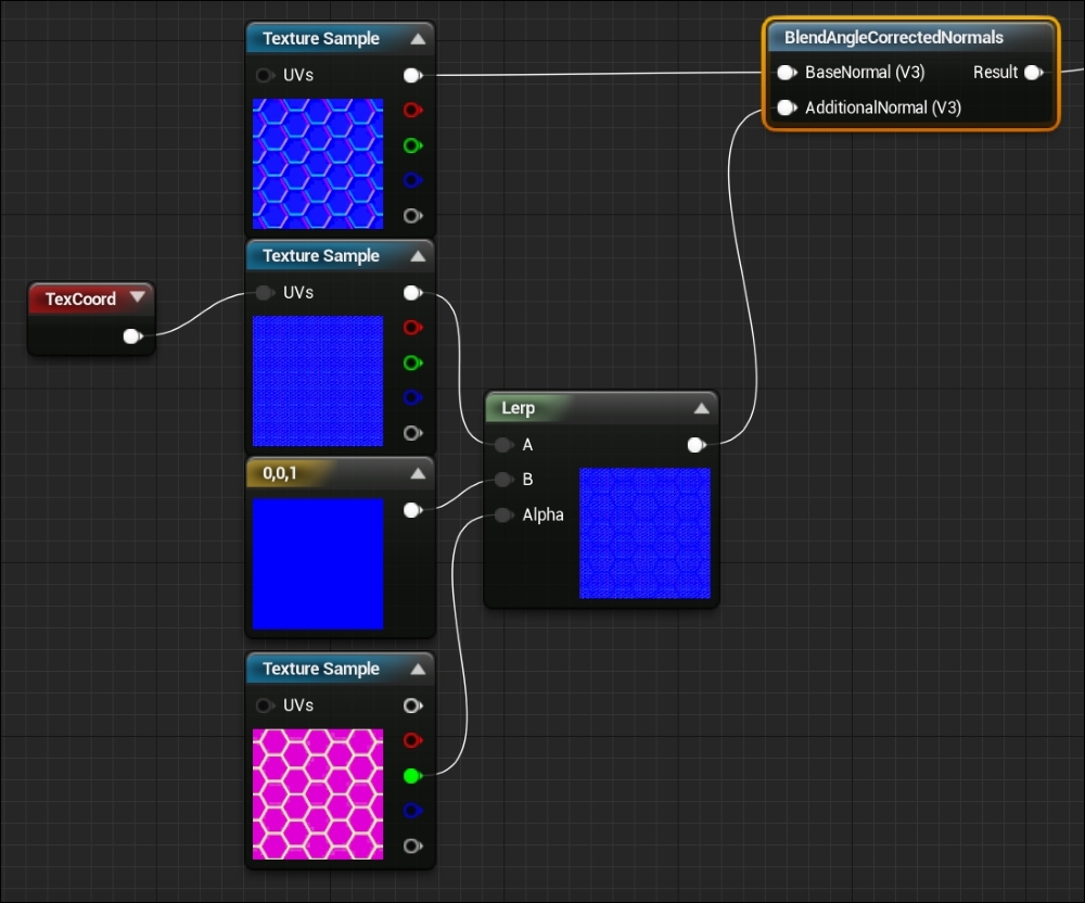
Underneath the Constant3Vector, summon another TextureSample expression and set the texture to be the mask we used earlier (T_Tech_Hex_Tile_M). Then summon another material expression called Linear Interpolate. We have used Lerps before in code and blueprint so I will not explain how this node works. However, we will plug the output of the UV tiled Texture Sample into A, the output of the Constant3Vector into B, and the Green channel of the mask into Alpha. All together it should appear as follows:
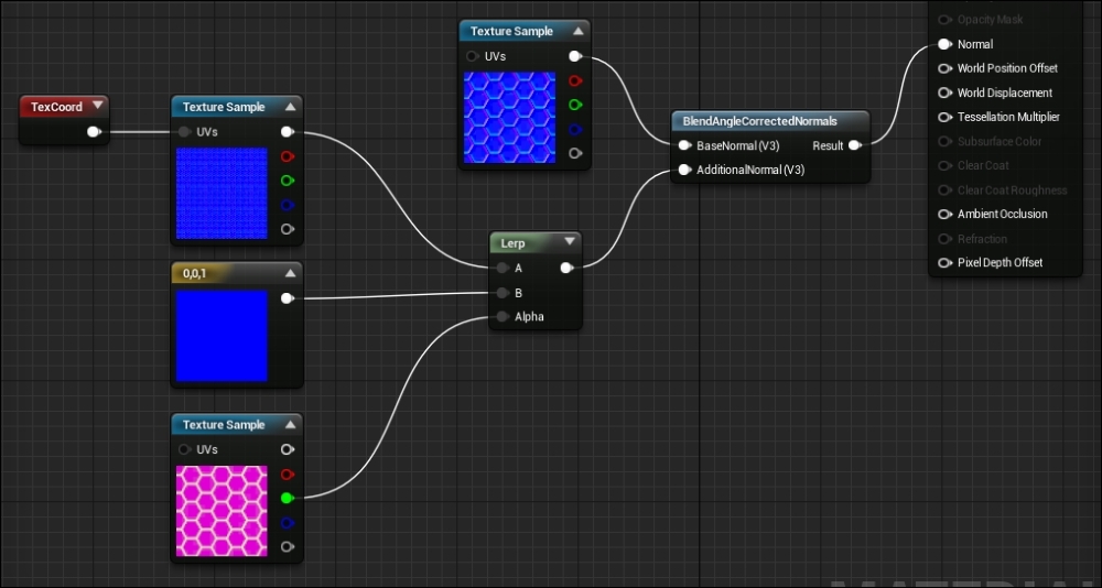
We now need to plug this output value into a special material expression that lets us blend normals together, it is called BlendAngleCorrectedNormals. Summon the expression now. This expression corrects the direction of normals that are blended on top of other normal maps. You can see the description of this expression by hovering your mouse over the node in the editor. We are going to be plugging our original untiled normal map sample into BaseNormal(V3) and our interpolated normal result into AdditionalNormal(V3). We will then take the output of this node and plug it into the Normal input of the main material expression node. All together it will appear as follows:
The output of this node arrangement will look like this:
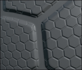
Yay! Nice clean detail regions. Now we can add our emissive color value back in!
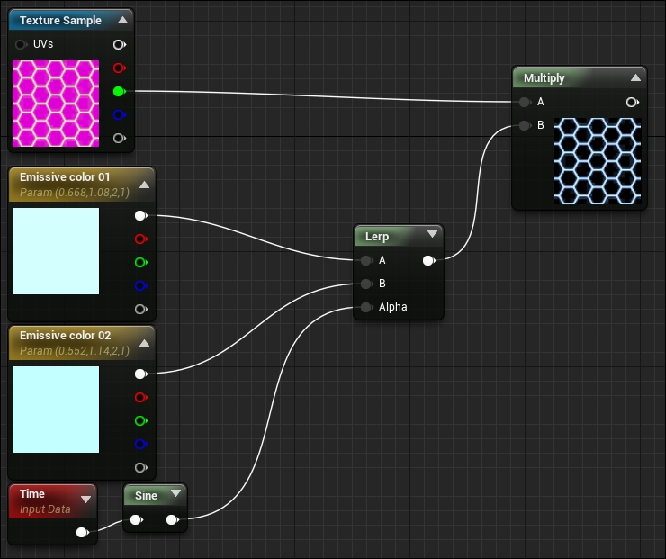
Instead of adding our emissive glow back in as it was before, we are going to be modifying the calculation so that the color pulses as a function of time. We are going to be interpolating between two emissive colors based off a sine ratio of real time! To do this we need to summon another VectorParameter expression, call this one Emissive Color 02. Set the color values of this vector parameter via the color picker to the following:
This is a slightly lighter color than Emissive Color 01. The next two expressions we need to summon are Time and Sine. Time is a simple expression that outputs the amount of real time that has passed since the application began. Sine is a simple expression that takes in a single float and outputs a sine ratio based on that value. As time increases, the sin ratio that is output will oscillate from -1 to 1. We can use this output to interpolate between our two emissive colors. We then need to pass the output of this interpolation to the mask calculation we were doing previously.
We can do this by summoning the Time and Sine expressions and a Linear Interpolate expression. Plug the value of Time into the Sine node, and the output of the Sine node into the Alpha parameter of the Lerp node. Plug Emissive Color 01 into the A input of the Lerp node, and Emissive Color 02 into the B input. Take the output of this Lerp node and plug it into the B input of the multiply node connected to our Mask Texture Sample. All together it will look like this:
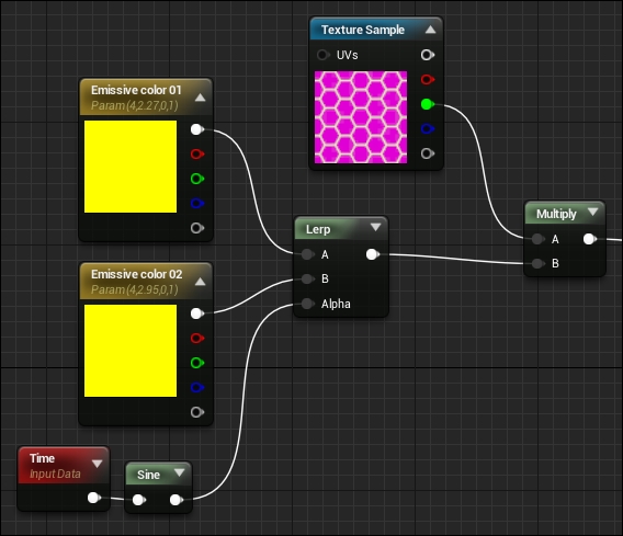
We can then plug the output of these calculations into the Emissive Color input of the final material node expression and we have our pulsing emissive glow! The last thing we need to do to our boss material is darken the base color and give it more of a metallic shine. We can do this by changing the base color vector parameter to 0 in each channel. For the metallic shine, create a Constant expression node, which is simply a single float value. Set this value to 0.4 and plug it into the Metallic and Roughness pins of the BossOutMaterial expression node.
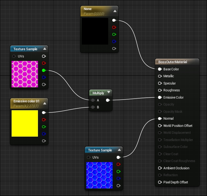
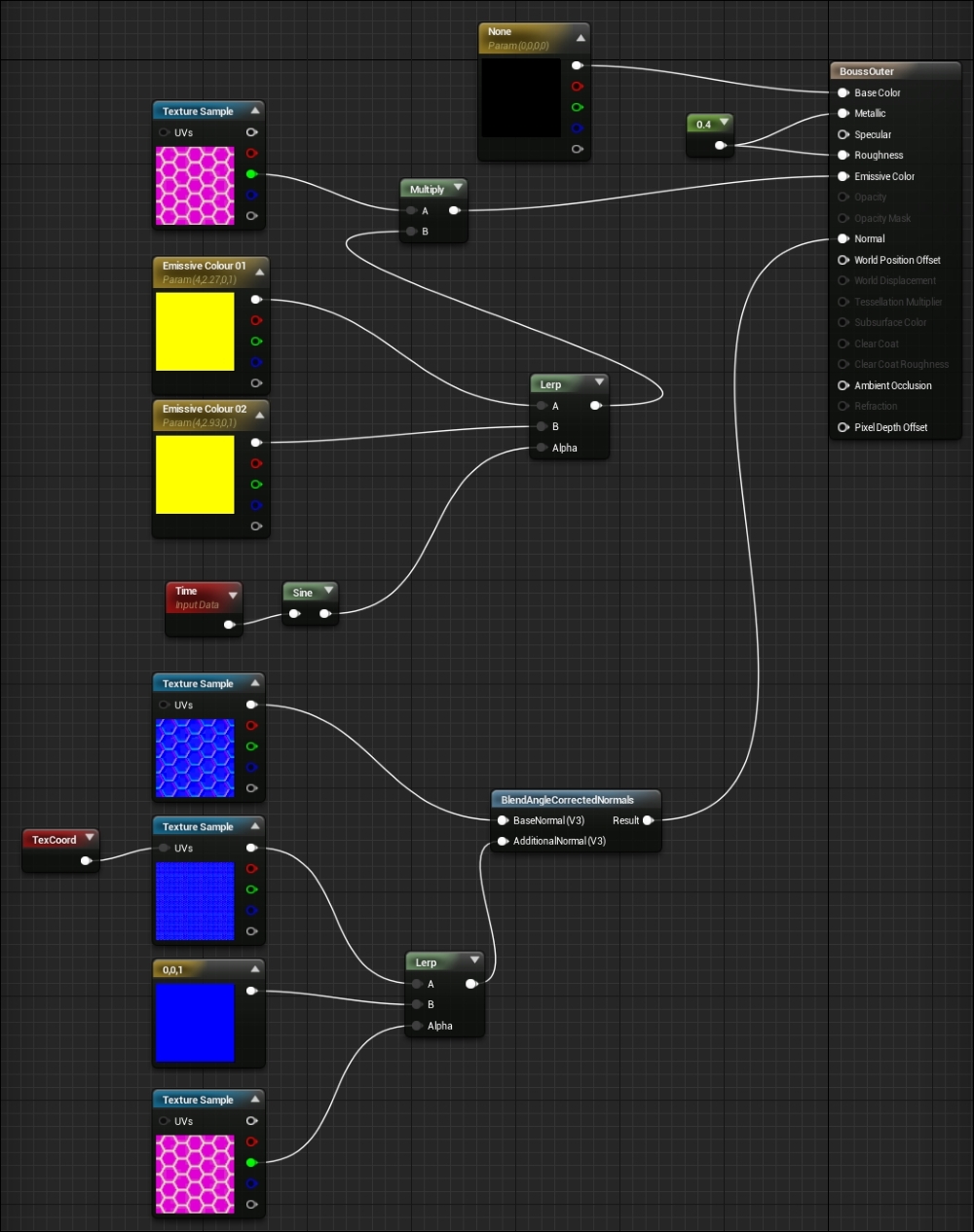
Your final graph should look similar to this:
Now that we have made the exterior shell of the boss glow a sinister yellow, it is now time to make the inner component of the boss mesh glow blue, with the Unreal U logo nice and bright. To do this we are not only going to have to perform similar masking and time-based calculations, but we are also going to have to mask out a section of the mesh based on texture coordinates so that we can separate the U logo part of the mesh from the rest. Create a new material called BossInnerMaterial and open it. The desired output from this material is something like this:

Ok, let's start by recreating the stuff we already know. Summon a Texture Sample expression and assign the T_Tile_Hex_Tile_M texture to it. Summon two VectorParameters, call them Emissive Color 01 and Emissive Color 02 respectively and ensure the color values of each match the following:
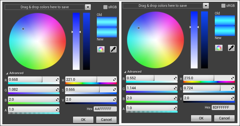
The left is for Emissive Color 01 and the right for Emissive Color 02. Next, summon a Time expression, a Sign expression, and a Liner Interpolation expression, and connect the nodes as we did for the previous material. Summon a Multiply node and connect the green channel of the Texture Sample to the A pin, and the output of the linear interpolation to the B pin. By the way, if you expand the Multiply node, you will be presented with a preview of the output of that calculation. Your node setup should appear as follows:
Now that we have done that, let's also recreate the normal map technique we used in the previous material as well. Summon two Texture Samples, both with T_Tech_Hext_Tile_N assigned to them as the texture, a Constant3Vector set to (0, 0, 1), and another Texture Sample, but this time with the T_Tile_Hex_Tile_M assigned. Summon a TextureCoordinate expression and set the U and V tiling to 8. Plug the output of this expression into one of the normal map texture samples (probably the second one). Then summon the LinearInterpolate and BlendAngleCorrectedNormals expressions. Plug the tiled texture sample into the A pin of the Lerp node, plug the constant3Vector into the B pin of the lerp node, and the green channel of the mask texture sample into the alpha input. Plug the result of this Lerp node into the AdditionalNormal input of the BlendAngleCorrectedNormals node, and plug the untiled texture sample of the normal map into the BaseNormal pin.
With all this in place, it should appear as follows:
Ok, now that we have our two node clusters that we know work in our previous material, we can adjust how these calculations work based on UV co-ordinates. The way artists project 2D textures to 3D meshes is via UV maps. Effectively, these maps are what the mesh would look like when the mesh is splayed out into 2D, much like if you were to make a cube out of paper and you have the cut-out in front of you before folding. This affords artists the ability to compose their textures so that they color specific areas of the mesh with the right details. I know that the UVs for the Unreal logo part of the BossMesh can be found in the lower half of the UV map (V values greater than 0.5). This means that any color changes that happen in the lower half of a texture are likely to only affect the Unreal logo. With this information in mind, we can make the Unreal U glow bright blue!
We need to create a calculation that will change any color value that has a texture co-ordinate with a V value greater than 0.5 to be our emissive color. To make things difficult we should also make sure that any normals found past a V co-ordinate of 0.5 are also set to be flat (0, 0, 1). We can do this by receiving a texture coordinate via the TextureCoordinate expression. Then by applying a mask to the output of the TexCoord node, so we are only working with the V channel, we can perform lerp and clamping calculations that will provide us with a 0 to 1 range value. Let's try this out.
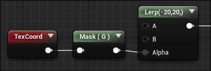
Summon a TextureCoordinate expression and then summon a new expression called Mask. This expression allows us to provide it with any format of value, a single float, a float2, a float3, and so on. Based on the properties set within the Details panel of this expression, it will return the appropriate data type with a given data set masked out. In our case we will be parsing it a UV float 2, asking it to only pass through the V channel masking U out.
We do this by selecting the Mask node and addressing the Details Panel. Under the Material Expression Component Mask section, toggle the G property to true. As this expression can be used for datatypes up to a float 4, the standard RGBA format is used here. As V is the second element in a float 2 and G is the second element in the float 4, this property configuration will work. What we have told this node to do is mask out all other components apart from G (element 2). So what this node will output for us is just the V value of the texture coordinate with U being masked out.
Summon a LinearInterpolate expression and plug the output of the Mask(G) node into the Alpha pin of the lerp node. We are going to be interpolating between a constant value of -20 and positive value of 20. Do this by selecting the Lerp node we just created and address the Details panel. Under the Material Expression Linear Interpolate section, set the ConstA property to -20 and the ConstB property to 20. So far, your node setup will look like this:
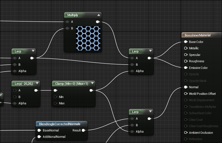
What we are going to do next is Clamp the value output from the Lerp node to be between 0 and 1. This is for two reasons. Firstly, we require a value of 0 to 1 to perform effective interpolation calculations. Secondly, as we just compressed a wide range of values (-20, to 20) to a short range of values (0.0 to 1.0), the rate in change of zero to 1 will be much more extreme. This will give us a clean mask of any V values past 0.5. If you wish to make the mask more vague, reduce the -20 to 20 range; if you want to make it sharper, increase the -20 to 20 range (to something like -100 to 100).
Summon a Clamp expression. By default, the clamp values are set to 0 and 1 respectively so all we have to do is plug the output of the Lerp node into this one. Following the clamp node, we need to create two Lerp expressions. Both of these expressions will have the clamped value we just created as their Alpha component. It is with these Lerps that we are doing the actual masking.
For the first Lerp we want to plug the output of the emissive-mask multiplication into the A pin, and the output of the emissive color calculation into the B pin. This means that anything past 0.5 V will receive our full emissive color without any normal mapping. As we know that our Unreal logo is located in the lower half of the UV map, this will guarantee the logo glows bright blue!
For the other Lerp we want to plug the result of our normal map addition calculation into the A pin, and into the B pin we want to plug a Constant3Vector with the value of (0, 0, 1). With all of this in place, the end of your material graph will appear as follows:
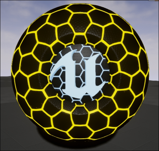
And the preview mesh (when set to a sphere mesh primitive) will look like this:
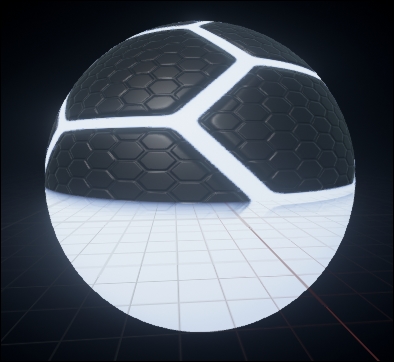
As you can see, anything in the lower half of the sphere is set to our emissive color! The result when applied to our boss mesh is that the Unreal U will glow bright blue!