
Froth Flotation
Flotation is undoubtedly the most important and versatile mineral separation technique, and both its use and application are continually being expanded to treat greater tonnages and to cover new areas. Recently celebrating its first centenary, flotation has permitted the mining of low-grade and complex ore bodies which would have otherwise been regarded as uneconomic. In earlier practice, the tailings of many gravity plants were of a higher grade than the ore treated in many modern flotation plants. Warranting its own history, at least one technology historian has described flotation as “perhaps the greatest single metallurgical improvement of the modern era”.
Keywords
Principle; collectors; frothers; regulators; sulfides; non-sulfides; kinetics; banks and circuits; testing; machines; gas dispersion; control; flowsheets
12.1 Introduction
Flotation is undoubtedly the most important and versatile mineral separation technique, and both its use and application are continually being expanded to treat greater tonnages and to cover new areas. Recently celebrating its first centenary (Fuerstenau et al., 2007), flotation has permitted the mining of low-grade and complex ore bodies which would have otherwise been regarded as uneconomic. In earlier practice, the tailings of many gravity plants were of a higher grade than the ore treated in many modern flotation plants. Warranting its own history (Lynch et al., 2010), at least one technology historian has described flotation as “perhaps the greatest single metallurgical improvement of the modern era” (Mouat, 1996).
Initially developed to treat the sulfide minerals of copper, lead, and zinc, flotation has expanded to include nickel, platinum- and gold-hosting sulfides, and to non-sulfide minerals including oxides such as hematite and cassiterite, and nonmetallic minerals such as fluorite, talc, phosphates, potash, and energy (fuel) minerals, fine coal and bitumen (Rao and Leja, 2004). Flotation now finds application outside the mining industry, deinking recycled paper pulp (Hardie et al., 1998) and deoiling oil refinery effluents (Rawlins, 2009), for example.
12.2 Principles of Flotation
Flotation is a separation process that exploits natural and induced differences in surface properties of the minerals, whether the surface is readily wetted by water, that is, is hydrophilic, or repels water, that is, is hydrophobic. If hydrophobic the mineral particle can attach to air bubbles and be floated. The system is complex, involving three phases (solids, water, and air) and the interaction of chemical and physical variables. The chemical variables aim to control the transition between the hydrophilic and hydrophobic state. Physical variables include those resulting from properties of the ore, such as particle size and composition (liberation), and machine-derived factors such as air rate and bubble size. Klimpel (1984) represented the interaction as a triangle: chemistry, ore, and machine. The mix of physics and chemistry often sees flotation described as a physicochemical based process.
The subject has been reviewed comprehensively by a number of authors, among the more recent being Crozier (1992), Harris et al. (2002), Johnson and Munro (2002), Fuerstenau and Somasundaran (2003), Nguyen and Schulze (2004), Rao and Leja (2004), Fuerstenau et al. (2007), and Bulatovic (2007, 2010).
The process of material being recovered by flotation from the pulp comprises three mechanisms:
1. Selective attachment to air bubbles (or “true flotation”).
2. Entrainment in the water which passes through the froth.
3. Physical entrapment between particles in the froth attached to air bubbles (often referred to as “aggregation”).
The attachment of valuable minerals to air bubbles is the most important mechanism and represents the majority of particles that are recovered to the concentrate. Although true flotation is the dominant mechanism for the recovery of valuable mineral, the separation efficiency (SE) between the valuable mineral and gangue is also dependent on the degree of entrainment and physical entrapment. Unlike true flotation, which is selective to the mineral surface properties, both gangue and valuable minerals alike can be recovered by entrainment and entrapment. Drainage of these minerals occurs in the froth phase and controlling the stability of this phase is important to achieve an adequate separation. In industrial practice, entrainment of unwanted gangue can be common and hence a single flotation stage is uncommon. Often, several stages of flotation (to form “circuits”) are required to reach an economically acceptable quality of valuable mineral in the final product.
True flotation exploits the differences in surface properties of particles of various minerals. After treatment with reagents, such differences in surface properties between the minerals within the flotation pulp become apparent and an air bubble is able to attach to a particle, and lift it (i.e., float it) to the water surface. This means the density of the bubble–particle aggregate is less than the density of the surrounding pulp.
Figure 12.1 illustrates the principle of true flotation in a mechanical flotation cell. The agitator provides enough turbulence in the pulp phase to promote collision of particles and bubbles, which results in the attachment of hydrophobic particles to bubbles (forming bubble–particle aggregates) and their transport into the froth phase for recovery.

The process can only be applied to relatively fine particles, because if they are too large, either the adhesion between the particle and the bubble will be less than the particle weight and the bubble will therefore drop its load, or the bubble–particle aggregate density will exceed that of the pulp. There is an optimum size range for flotation (Trahar and Warren, 1976; Crawford and Ralston, 1988; Finch and Dobby, 1990), and continual research to expand the size range (Jameson, 2010; Wyslouzil et al., 2013).
In flotation concentration, the valuable mineral is usually transferred to the froth, or float fraction, leaving the gangue in the pulp or tailings. This is direct flotation and the opposite is reverse flotation, in which the gangue is separated into the float fraction.
A function of the froth phase is to retain the collected particles and transport them to the overflow. Another function is to enhance the overall selectivity of the flotation process. The froth achieves this by allowing entrained material to drain while preferentially retaining the attached material. This increases the concentrate grade while limiting the reduction in recovery of valuables. The relationship between recovery and grade is a trade-off that needs to be managed according to operational constraints.
The mineral particles can only attach to the air bubbles if they are to some extent hydrophobic. Having reached the surface of the pulp, the air bubbles only continue to support the mineral particles if they can form a stable froth, otherwise they will burst and drop the mineral particles. To achieve these conditions, it is necessary to use the numerous chemical compounds known as flotation reagents.
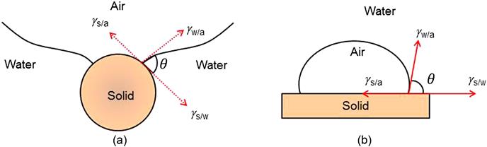
The forces tending to hold a particle to a bubble are shown in Figure 12.2(a), with the common depiction of the contact angle (by convention measured in the liquid) in Figure 12.2(b). The tensile forces lead to the development of an angle between the mineral surface and the bubble surface. At equilibrium:
(12.1)
where γs/a, γs/w, and γw/a are the surface tensions (or energies) between solid and air, solid and water, and water and air, respectively, and θ is the contact angle between the mineral surface and the bubble.
The force required to break the particle–bubble interface is called the work of adhesion, Ws/a, and is equal to the work required to separate the solid–air interface and produce separate air–water and solid–water interfaces:
(12.2)
Combining with Eq. (12.1) gives:
(12.3)
It can be seen that the greater the contact angle the greater is the work of adhesion between particle and bubble and the more resilient the system is against disruptive forces. The hydrophobicity of a mineral therefore increases with the contact angle; minerals with a high contact angle are said to be aerophilic, that is, they have a higher affinity for air than for water. The terms hydrophobicity and floatability are often used interchangeably. Hydrophobicity is a necessary condition, but floatability incorporates other particle properties, such as particle size, that affect amenability to flotation.
When a particle and bubble collide in the pulp attachment is not instantaneous but requires time, referred to as induction time. Induction time is associated with the properties of the thin water film that separates the particle and bubble just before attachment. For a hydrophobic surface, induction time is short, a few milliseconds, and if it is less than the time the particle and bubble are in contact, attachment is successful and the particle is floated. With a hydrophilic surface the induction time is large and exceeds the particle–bubble contact time. Both contact angle and induction time are used to characterize surface properties related to flotation (Chau et al., 2009; Gu et al., 2003)
Most minerals are not water-repellent in their natural state and flotation reagents must be added to the pulp. The most important reagents are the collectors, which adsorb on mineral surfaces, rendering them hydrophobic and facilitating bubble attachment. Regulators are used to control the flotation process; these either activate or depress mineral attachment to air bubbles and are also used to control particle dispersion and the pH of the system. Frothers help produce the fine bubbles necessary to increase collision rates and to help maintain a reasonably stable froth. Reviews of flotation reagents and their application include those of Ranney (1980), Crozier (1984), Somasundaran and Sivakumar (1988), Ahmed and Jameson (1989), Suttill (1991), Adkins and Pearse (1992), Nagaraj (1994), Buckley and Woods (1997), Ralston et al. (2001), Fuerstenau and Somasundaran (2003), Nagaraj and Ravishankar (2007), and Bulatovic (2007, 2010).
12.3 Classification of Minerals
All minerals are classified into polar or nonpolar types according to their surface characteristics. The surfaces of nonpolar minerals are characterized by relatively weak molecular bonds. The minerals are composed of covalent molecules held together by van der Waals forces, and the nonpolar surfaces do not readily attach to the water dipoles, and in consequence are naturally (inherently) hydrophobic, with contact angles between 60° and 90°. Minerals of this type, such as graphite, sulfur, molybdenite, diamond, coal, and talc, thus have high natural floatabilities. Although it is possible to float these minerals without the aid of chemical agents, it is common to increase their hydrophobicity by the addition of hydrocarbon oils. Fuel oil, for example, is widely used to increase the floatability of coal. Layered minerals, such as molybdenite and talc, break to reveal polar edges and largely nonpolar faces; on balance they are hydrophobic but tend to become less hydrophobic as the particle size reduces, as the balance of edge to face increases.
Minerals with strong covalent or ionic surface bonding are known as polar types and react strongly with water molecules; these minerals are naturally hydrophilic.
Hydrophilicity is associated with high solid surface energy and hydrophobicity with low solid surface energy, where high and low are relative to the surface energy of water (γw/a~72 mJ m−2). Solid surface energy can be measured using inverse gas chromatography, a technique that is being adapted to characterize the mineral surface in flotation systems (Ali et al., 2013). These measurements reveal that surfaces are heterogeneous, having a distribution of energy sites. Accordingly, any measure such as contact angle and induction time should be taken as an average value.
The nature of the interaction of a surface with water is illustrated in Figure 12.3 for quartz, a strongly hydrophilic mineral. Freshly broken, a quartz surface has unsatisfied (“dangling”) Si and O bonds, which hydrolyze to form SiOH (silanol) groups, which in turn hydrogen bond with water dipoles. Whenever interaction with water to form this hydrated surface is identified it indicates a hydrophilic surface.

The polar group of minerals has been subdivided into various classes depending on the magnitude of polarity (Wrobel, 1970), which increases from groups 1–5 (Table 12.1). Apart from the native metals, the minerals in group 1 are all sulfides, which are only weakly polar due to their covalent bonding, which is relatively weak compared to the ionic bonding of the silicate, carbonate, and sulfate minerals. In general, therefore, the degree of polarity, and thus surface energy and hydrophilicity, increases from sulfide minerals, through sulfates, to carbonates, halites, phosphates, etc., then to oxides–hydroxides, and, finally, silicates and quartz, which are strongly hydrophilic.
Table 12.1
Classification of Polar Minerals
| Group 1 | Group 2 | Group 3(a) | Group 4 | Group 5 |
| Galena | Barite | Cerrusite | Hematite | Zircon |
| Covellite | Anhydrite | Malachite | Magnetite | Willemite |
| Bornite | Gypsum | Azurite | Gothite | Hemimorphite |
| Chalcocite | Anglesite | Wulfenite | Chromite | Beryl |
| Chalcopyrite | Ilmenite | Feldspar | ||
| Stibnite | Group 3(b) | Corundum | Sillimanite | |
| Argentite | Fluorite | Pyrolusite | Garnet | |
| Bismuthinite | Calcite | Limonite | Quartz | |
| Millerite | Witherite | Borax | ||
| Cobaltite | Magnesite | Wolframite | ||
| Arsenopyrite | Dolomite | Columbite | ||
| Pyrite | Apatite | Tantalite | ||
| Sphalerite | Scheelite | Rutile | ||
| Orpiment | Smithsonite | Cassiterite | ||
| Pentlandite | Rhodochrosite | |||
| Realgar | Siderite | |||
| Native Au, Pt, Ag, Cu | Monazite |

The nature of the surface is complicated by the fact that all minerals release ions to solution. Some minerals are semisoluble and some, like sylvite and halite, are soluble and processing is in their brine. In many cases, Ca and Mg species are present in the process waters.
Sulfide minerals require a little further consideration as they are reactive with oxygen dissolved in the process water. Figure 12.4 shows a series of reactions producing an “oxidized” surface comprising groups such as M-OH and sulfoxy species (SxOy2−) depending on pH and oxidizing conditions. These species represent hydrophilic sites, which H-bond with water, adding to the hydrated layer and making the surface more hydrophilic. One oxidation product shown is S–S–S, a metal deficient sulfide or polysulfide, the sulfurs bonding to each other as the metal ion is removed. In contrast to the other oxidation products, this represents a hydrophobic site. These oxidation reactions and resultant species come into play in interpreting flotation response.

12.4 Collectors
Hydrophobicity has to be imparted to most minerals in order to float them. To achieve this, surfactants known as collectors are added to the pulp and time is allowed for adsorption during agitation in what is known as the conditioning period. Collectors are organic compounds which render selected minerals water-repellent by adsorption on to the mineral surface, reducing the stability of the hydrated layer separating the mineral from the air bubble to such a level that attachment of the particle to the bubble can be made; that is, collectors reduce the induction time.
Collectors may be nonionizing compounds, which are practically insoluble and strongly hydrophobic. An example is kerosene. These collector types are used with naturally hydrophobic minerals such as coals and molybdenite to boost their floatability, sometimes referred to as oil-assisted flotation (Laskowski, 1992). They adsorb through hydrophobic interaction, the natural tendency of hydrophobic entities to repel water and come together. A variation is to first coat the bubbles with oil, referred to as oily bubble flotation (Su et al., 2006). In some situations, an insoluble collector forms (referred to as a collector colloid) and appears to adsorb first on the bubble and is then transferred to the mineral surface upon collision (Burdukova and Laskowski, 2009).
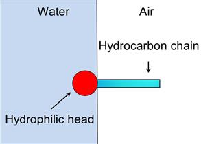
Soluble, ionizing collectors are the more common form and have found wide application. They are heteropolar, that is, the molecule contains a nonpolar hydrocarbon group (hydrocarbon chain, R) and a polar group, which may be one of a number of types. The nonpolar hydrocarbon radical has pronounced water-repellent properties, while the polar group gives the molecule its solubility. The polar group is the functional (or reactive) group and it is through this group that reaction with sites on the mineral surface occurs (i.e., adsorption). Adsorption can be chemical or physical, as discussed in Sections 12.4.3 and 12.4.4. Figure 12.5 shows the general result of adsorption, with the nonpolar hydrocarbon chain oriented toward the water, making the site hydrophobic. Surface coverage by collector could be up to a monolayer (or more) but is usually far less. Provided the surface hydrophobic sites overcome the hydrophilic sites, on balance the particle becomes floatable.

Ionizing collectors can be classed by the type of ion, anionic or cationic, or their major application, non-sulfide minerals or sulfide minerals. Figure 12.6 combines both classifications. Table 12.2 summarizes some of the major collectors with typical applications.

Table 12.2
Major Collectors and Example Applications
| Collector Family | General Formula | R Value | Application | |
| Sulfide minerals | Xanthate, alkyl |  |
C2–C8 | Mostly for Cu, Zn, Cu–Mo, Au, PGM, Ni, and oxidized minerals |
| Dithiophosphate, dialkyl |  |
C2–C6 | Widely used with xanthates for PGM, Fe, Cu, Pb, Cu–Mo, Cu, Au, and complex sulfides | |
| Dithiocarbamate, dialkyl |  |
C2–C6 | PGM ores, Cu, Pb | |
| Dithiophosphinate, dialkyl |  |
C2–C4 | Widely used, especially for complex sulfides, e.g., Pd complexes with S and Se | |
| Thionocarbamate, dialkyl |  |
C2–C4 | Widely used for Cu, Cu–Mo | |
| Non-sulfide minerals | Fatty acids and their salts |  |
C8–C22 | Widely used for P, ZnO, CuO, Ni, Nb, Ti, Cu–Co, Sn, W |
| Primary amines |  |
C12–24 | Widely used, e.g., quartz, ZnO, Ti, Sn | |
| Amine ether | C6–C13 | Quartz, Al silicates | ||
| Petroleum sulfonates |  |
C14–C17 | Widely used, e.g., Ti, W, Fe | |
| Hydroxamates |  |
C5–C14 | Rare earths; Sn, W, Mn, Al silicates, quartz | |

Source: Adapted from Nagaraj and Ravishankar (2007).
Anionic collectors consist of two types according to the structure of the polar group: sulfhydryl type and oxyhydryl type. The term sulfhydryl refers to the SH group present in undissociated form of the collector. The term thiol refers to carbon bonded to the SH, that is, C-SH or R-SH. Both sulfhydryl and thiol (thio) are used to describe this class of collectors. They are widely used in the flotation of sulfide minerals (Avotins et al., 1994). The other anionic type of collectors is oxyhydryl (referring to the OH group), and they are mainly used in non-sulfide flotation. Compared to the sulfhydryl collectors, the hydrocarbon chain is usually longer. Typically supplied as salts of Na or K, these cations play no role in the action of these anionic collectors.
Cationic collectors are based on pentavalent nitrogen, primary (fatty) amines (i.e., amines with one R radical) and ether amines being the most common (Nagaraj and Ravishankar, 2007). The hydrocarbon chain is typically C12–24, and the anion is usually a halide which plays no direct role in the collector action. They are used primarily for non-sulfides.
Other collector classes are amphoteric reagents and chelating reagents (Somasundaran and Moudgil, 1987). Amphoteric collectors possess cationic and anionic functions, depending on pH. They have been used to treat sedimentary phosphate deposits (Houot et al., 1985) and to improve the selectivity of cassiterite flotation (Broekaert et al., 1984). Chelating reagents have been suggested as flotation collectors in view of their ability to form stable compounds with selected cations. Their action with metal ions in bulk solution is well understood, the difficulty is translating this action to metal ions on a mineral surface. Whether another collector class based on nanoparticle technology emerges remains to be seen (Yang et al., 2012).
Collectors are usually used in small amounts as increased concentration, apart from the cost, tends to float other minerals, reducing selectivity. It is always harder to eliminate a collector already adsorbed than to prevent its adsorption. Over-dosing with collector can lead to froth stability issues, ranging from immobility to collapse and can induce bubble clustering in the pulp, that is, arrays of bubbles bridged by particles, which can potentially entrap gangue.
Increasing chain length of the hydrocarbon radical increases the level of hydrophobicity imparted to the particle, that is, makes for a more powerful collector, but often one with less selectivity. Table 12.2 shows that chain length is commonly longer with collectors for non-sulfides than for sulfides. This difference can be attributed to non-sulfides being generally more strongly hydrophilic compared to sulfides (Table 12.1) which the longer hydrocarbon chain helps overcome. Chain length is limited by solubility.
It is common to add more than one collector to a flotation system. A selective collector may be used at the head of the circuit, to float the highly hydrophobic particles, after which a more powerful, but less selective one, is added to promote recovery of the slower floating particles. Mixed collectors are used. Guidelines for mixed sulfhydryl collectors are given by Lotter and Bradshaw (2010). Lee et al. (2009) used combinations of sulfhydryl (xanthate) and oxyhydryl (hydroxamate) collectors for mixed sulfide/oxide ores. Kerosene is used as an auxiliary collector with oxyhydryl collectors in non-sulfide flotation (Nagaraj and Ravishanakar, 2007).
There are hundreds of collectors that have been developed over the century of flotation and just some of the more important ones are included here. For more detail there have been some recent reviews (Nagaraj and Ravishankar, 2007; Bulatovic, 2007, 2010; Nagaraj and Farinato, 2014a). Reagent supplier handbooks also remain a useful resource.
12.4.1 Collectors for Non-sulfide Minerals
Among the oxyhydryl collectors, fatty acids dominate in non-sulfide flotation. The salts of oleic acid, such as sodium oleate, and of linoleic acid are commonly employed. They are used for the flotation of minerals of calcium, barium, strontium, and magnesium, the carbonates of non-ferrous metals, and the soluble salts of alkali metals and alkaline earth metals (Finch and Riggs, 1986).
After fatty acids, the next largest application is amines, followed by petroleum sulfonates. Dodecylamine and other long chain alkyl amines are excellent collectors for quartz, for example, in reverse flotation from iron concentrates. Petroleum sulfonates possess similar properties to fatty acids, with less collecting power, but partly as a consequence, greater selectivity. They are used for recovering barite, celestite, fluorite, apatite, chromite, kyanite, mica, cassiterite, and scheelite (Holme, 1986).
By convention referred to as hydroxamates they are used as the acid (alkyl hydroxamic acid). They are chelating agents and typically have a carbon chain C6 to 14. The hydroxyl group and the carbonyl (C![]() O) group can form stable chelates with many metal cations (e.g., iron, manganese, copper, rare-earth elements) (Türkel, 2011). They are used in collection of minerals such as pyrochlore, muscovite, phosphorite, hematite, pyrolusite, rhodonite, rhodochrosite, chrysocolla, malachite, bornite, calcite, and gold and other precious metals. Hydroxamates have proved more effective than fatty acids in recovery of bastnaesite (a rare earth fluocarbonate) (Pradip and Fuerstenau, 2013), and in removal of anatase to improve brightness of kaolin clay (Yoon et al., 1992).
O) group can form stable chelates with many metal cations (e.g., iron, manganese, copper, rare-earth elements) (Türkel, 2011). They are used in collection of minerals such as pyrochlore, muscovite, phosphorite, hematite, pyrolusite, rhodonite, rhodochrosite, chrysocolla, malachite, bornite, calcite, and gold and other precious metals. Hydroxamates have proved more effective than fatty acids in recovery of bastnaesite (a rare earth fluocarbonate) (Pradip and Fuerstenau, 2013), and in removal of anatase to improve brightness of kaolin clay (Yoon et al., 1992).
The oxyhydryl collectors have been used to float cassiterite, but have now been largely replaced by other reagents such as arsonic and phosphonic acids and sulfosuccinamates (Baldauf et al., 1985).
12.4.2 Collectors for Sulfide Minerals
The most widely used sulfhydryl collectors are xanthates, dithiophosphates, and the carbamates (Adkins and Pearse, 1992). The reaction with the surface is through a sulfur atom, the bonding properties being modified by neighboring atoms, especially by N and O, and other groups.
Mercaptans are the simplest thiol compounds, the ionic form having the general formula R-S−. The chain length is usually C2 to C8. Mercaptans have been used as selective collectors for some refractory sulfide minerals (Shaw, 1981). Chen et al. (2010) report the use of dodecyl (C12) mercaptan as collector in flotation of auriferous pyrite and arsenopyrite.
Xanthates are the most important thiol collectors. Different from mercaptans, the hydrocarbon chain (R) is not bonded directly to the sulfur, but via an O–C linkage. They are available with alkyl chains ranging from C2 to C6 (or higher) of any isomeric type (Adkins and Pearse, 1992). The common alkyl chains are ethyl, isopropyl, isobutyl, and amyl. An example structure is given in Figure 12.7(a). Xanthates have good water solubility and stability in alkaline conditions with relatively low cost and ease of manufacture, transport, storage, and handling. However, because they interact with all sulfides (sphalerite and pyrrhotite being partial exceptions with short chain xanthates), xanthates require regulating agents in order to achieve selectivity between sulfide minerals.

Xanthates have the disadvantage of decomposing to CS2, which poses a health hazard, and in discharge waters excess xanthate can create toxic conditions for aquatic life. This is prompting the search for “green” (i.e., environmentally friendly) alternatives to xanthate (Dong and Xu, 2011).
Dithiophosphates are the second most common thiol collectors and their use dates back to 1920 (Crozier 1991; Adkins and Pearse, 1992). An example structure is given in Figure 12.7(b). In dithiophosphate collectors pentavalent phosphorus replaces the tetravalent carbon, with now two oxygen atoms linking to their respective hydrocarbon chains. Dithiophosphates can be used alone, but are usually used in conjunction with xanthates or other collectors. They are available with alkyl chains ranging from C2 to C6 (or higher) of any isomeric type.
In dithiocarbamates nitrogen replaces oxygen in the otherwise xanthate-type structure. Compared to xanthate, both dithiophosphates and dithiocarbamates are more stable over a wider range of pH (Ngobeni and Hangone, 2013).
The structure of the collectors determines their interaction with the mineral. Oxygen is a strong electronegative atom and in xanthates withdraws electrons from the sulfur, reducing the electron density, which reduces its reactivity compared to mercaptans. The two oxygen atoms in dithiophosphates reduce the electron density on the sulfur even further, making these collectors less reactive than xanthate. In contrast, with dithiocarbamate, the nitrogen being less electronegative than oxygen makes this collector more reactive than xanthate. The more reactive the collector, in general, the less selective. Putting this together, the general sequence of selectivity is: dithiocarbamates < xanthates < dithiophosphates (Somasundaran and Moudgil, 1987). One target in identifying more selective reagents is to reduce the large consumption of lime often needed to achieve selectivity against pyrite using xanthate.
Dithiophosphinate (represented by Cytec’s R3418A) is structurally similar to dithiophosphate but the R groups are directly bonded to the P atom. The lack of O or N preserves the electron density on the sulfur making this collector quite reactive. The metal complexes of dithiophosphinate are several orders of magnitude more stable than those of dithiophosphate (Güler et al., 2006).
Thionocarbamates are chelating collectors, chelation with surface metal ions taking place through two members, the C![]() S and N–H groups, forming stable complexes (Somasundaran and Moudgil, 1987). The Z200 reagent introduced by Dow was O-isopropyl N-ethyl thionocarbamate (referring to isopropyl being bonded to the O atom, and ethyl to the N atom). A common reference to this reagent today is isopropyl ethyl thionocarbamate (IPETC). A modified thinocarbamate, ethoxycarbonyl alkyl thionocarbamate, reacts as a six member chelate.
S and N–H groups, forming stable complexes (Somasundaran and Moudgil, 1987). The Z200 reagent introduced by Dow was O-isopropyl N-ethyl thionocarbamate (referring to isopropyl being bonded to the O atom, and ethyl to the N atom). A common reference to this reagent today is isopropyl ethyl thionocarbamate (IPETC). A modified thinocarbamate, ethoxycarbonyl alkyl thionocarbamate, reacts as a six member chelate.
Table 12.3 gives examples of collector types and dosages taken from Canadian practice (Damjanović and Goode, 2000). The prevalence of xanthate is evident. Consumption is typically quoted on the basis of kg per ton ore, but dividing by the head grade gives consumption on the basis of kg per ton metal, which makes for comparison between operations. As the Table shows, collector consumption ranges from about 1–4 kg t−1 metal. There is some indication that the concentration in solution is also important, sometimes a factor in matching laboratory and plant conditions where pulp density (% solids) can be quite different.
Table 12.3
Example Collector Types and Dosage Based on Metal Tons from Canadian Practice (Damjanović and Goode, 2000)
| Operation | Metals | Collector | Dosage (kg t−1 metal) |
| Strathcona Mill | Ni–Cu | PIBX | 2.8 (Ni+Cu) |
| Clarabelle Mill | Ni–Cu | SAX | 2.1 (Ni+Cu) |
| Thomson | Ni–Cu | SAX | 1.3 (Ni+Cu) |
| Louvicourt Mine | Cu–Zn–Au–Ag | Aerophine 3418A | 1.6 (Cu) |
| PAX 51 | 0.5 (Cu) | ||
| Flex 41 | 0.5 (Zn) | ||
| Les Mine Selbaie | Cu–Zn–Au–Ag | SIPX | 1.1 (Cu) |
| SP129 | 0.6 (Zn) | ||
| Myra Falls | Cu–Zn–Au–Ag | PAX: Aerofloat 208 | 0.7 (Cu+Zn) |
| (73:27 blend added to both circuits) | 1.5 (Cu+Zn) | ||
| Mine Bouchard-Hebert | Cu–Zn–Au–Ag | 3418A (to Cu circuit) | 3.5 (Cu) |
| 3148A (to Zn circuit) | 0.7 (Zn) | ||
| Aerofloat 208 | 2.1 (Cu) | ||
| Mine Langlois | Cu–Zn–Au–Ag | 208 (to Cu circuit) | 3.3 (Cu) |
| 3418 (to Cu circuit) | 5.4 (Cu) | ||
| 3418 (to Zn circuit) | 0.6 (Zn) | ||
| Matagami Mine | Cu–Zn–Au–Ag | Aero 3477 (to Cu circuit) | 4.6 (Cu) |
| Aero 3418A (to Cu circuit) | 0.4 (Cu) | ||
| Aero 3418A (to Zn circuit) | 0.5 (Zn) | ||
| Brunswick Mine | Pb–Zn–Cu (Ag) | 80:20 SIPX:PAX | 1.8 (Pb+Zn+Cu) |
| Aero 241 | 0.1 (Pb+Cu) | ||
| Aerophine 5100 | 0.1 (Cu) | ||
| Heath Steele | Pb–Zn–Cu (Ag) | SIPX | 1.0 (Pb+Zn+Cu) |
| Aero 241 | 0.3(Pb+Zn+Cu) | ||
| Aerophine 5100 | 0.2 (Pb+Zn+Cu) |

Key (family type for trade name reagents): PIBX, potassium isobutyl xanthate; SAX, sodium amyl xanthate; SP129, blend of dithiophosphate and mercaptobenzothiazole plus diamine modifier; Aerophine 3418A, dithiophosphinate; PAX, potassium amyl xanthate; Flex 41, xanthate; SIBX, sodium isobutyl xanthate; Aerofloat 208, dithiophosphate; Aero 3477, dithiophosphate; Aero 241, dithiophosphate; Aerophine 5100, allyl isobutyl thionocarbamate.
Understanding the collector structure–activity relationship is probably the largest topic in basic flotation research. The target is to design collectors tailored to meet particular mineral recovery and selectivity needs (Somasundaran and Wang, 2006; Abramov, 2011; Nagaraj and Farinato, 2014a). Molecular modeling has been applied (e.g., Pradip and Rai, 2003). The challenge limiting that approach is modeling the mineral surface under flotation conditions.
12.4.3 Collector Adsorption in Non-sulfide Mineral Systems
In non-sulfide mineral flotation, the anionic oxyhydryl and cationic amines are the prime collectors. The wide range in non-sulfide mineral types, from soluble, to semisoluble to insoluble, suggests that one collector adsorption mechanism will not fit all cases. Nevertheless, the two general mechanisms, chemical and physical, apply.
Chemical adsorption, or chemisorption, refers to the formation of chemical bond between the collector and, usually, the metal cation in the mineral surface. The reaction falls under the general electron donor/electron acceptor model. Reaction with fatty acid (e.g., oleate) provides an example of chemisorption through formation of calcium oleate as precipitates and surface compounds (Hu et al., 1986; Rao et al., 1991). The possible surface reaction is given in Figure 12.8. In this example, the oxygen of the COO− functional group is the electron donor, the calcium the electron acceptor.

The second mechanism, physical adsorption, is through electrostatic interaction. Collector adsorption by this mechanism is illustrated in Figure 12.9(a) for the flotation of goethite with two 12-carbon collectors, dodecyl sulfate (R-SO4−) and dodecylamine (R-NH3+). With the anionic collector flotation is successful to about pH 6 at which flotation with the cationic collector starts. The explanation for this different response lies in the fact that particles in water carry a surface charge, and it is through this charge that electrostatic interaction with the ionic group of the collector occurs.
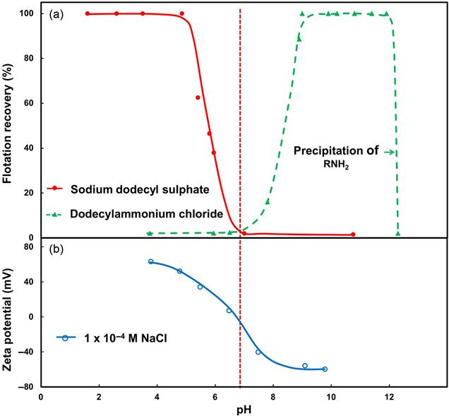
The common measure of surface charge is zeta potential (ζ), as in Figure 12.9(b). Measurement of zeta potential is described in any standard surface chemistry text (see also Chapter 15). For goethite, the zeta potential is positive at pH less than about pH 6.7 and becomes negative at higher pH. The anionic collector (i.e., with positively charged head group) is electrostatically attracted to the goethite at pH < 6.7 and the cationic collector is electrostatically attracted at pH > 6.7, thus explaining the different flotation-pH response to the two reagents. The resulting adsorption is referred to as physical adsorption or physisorption, which does not result in a chemical bond.
The origin of the charge on goethite is illustrated in Figure 12.10. Considering just the Fe and O sites, by analogy with the situation described for quartz (Figure 12.3) these sites are hydrated. When the pH is low, in the case of goethite below ca. pH 6.7, the OH is removed from some Fe sites by reaction with H+ (to form H2O) leaving a net positive charge, while at pH > 6.7 the H from some O sites is removed by reaction with OH− leaving a net negative charge. For many minerals this interpretation of the effect of pH on zeta potential applies and OH− and H+ are referred to as potential determining ions. The pH when the charge is zero is the iso-electric point (IEP, as marked on Figure 12.9). The IEP is sometimes referred to as the point of zero charge, PZC.

The IEP is characteristic of the mineral and values are in the literature (Shergold, 1984; Parks, 1965); in the case of goethite, from Figure 12.9(b), the IEP is about pH 6.7, which is similar to the other major iron minerals, hematite and magnetite. If physisorption is the principal interaction mechanism, for any mineral at pH < IEP anionic collectors are effective; and at pH > IEP cationic collectors are effective. This is known as the electrostatic model of flotation (Fuerstenau, 2007).
The division in surface charge at IEP is not exact. Surface charge is a net value, consequently there are some negative sites at pH < IEP and positive sites at pH > IEP that can interact with oppositely charged collectors. This is in evidence using more hydrophobic longer chain C18 collectors in place of the C12 collectors in Figure 12.9(a), which will show greater pH overlap in the flotation response (Fuerstenau, 2007).
Both chemical and electrostatic interaction can be involved in collector adsorption. For example, pyrolusite has an IEP ~ pH 7.4 but oleate adsorption shows two flotation response regions, one below pH 7.4 and one above pH 7.4 (Fuerstenau and Palmer, 1976). Adsorption of oleate at pH below the IEP is compatible with electrostatic adsorption (pyrolusite is positively charged, oleate negatively charged), while at pH above the IEP a Mn–oleate chemical bond is identified.
Not all minerals can be treated as having uniform surfaces. Layered minerals break to expose a largely uncharged face and a charged edge with which charged collectors may interact. These mineral pose challenges in identifying interaction mechanisms (Yin and Miller, 2012).
The difference in IEP between minerals can be used as a guide to the collector-pH conditions for selective flotation. For example, the IEP of quartz is close to pH 3, compared to the pH 6.7 for goethite, thus in the range pH 3–6.7, a cationic collector should selectively recover quartz or an anionic collector selectively recover goethite. Identifying this “pH window” is often a good start, but there are a number of confounding factors that make the choice of selective flotation conditions less direct. The reverse flotation of quartz in processing iron ores using amine, rather than at pH 3–6.7, flotation is at alkaline pH with polysaccharide (starch) to depress the iron oxide minerals (Araujo et al., 2005a). Other confounding factors, including the variation in solution species with pH, are discussed in Section 12.7.
Electrostatic interactions not only contribute to adsorption of collectors, but also influence particle–particle interactions. In the goethite–quartz case over the pH range 3–6.7, the two minerals are oppositely charged and thus are electrostatically attracted to each other. Aggregation of particles due to electrostatic effects is known as coagulation and since in this case the aggregates are of mixed minerals, the process is heterocoagulation. (Coagulation and the related processes return in Chapter 15.) One form of heterocoagulation is slime coating, the coating of fine particles of one mineral onto oppositely charged particles of another. Clearly counterproductive, heterocoagulation is one of the confounding factors in processing iron ores in the pH range 3–6.7; by processing at alkaline pH the iron minerals and quartz both carry negative charge and are electrostatically repelled and dispersed.
Rather than adsorbing as ions, some collectors appear to come out of solution as colloidal precipitates (collector colloids) that interact electrostatically with particles. In potash flotation in saturated brines, one proposed mechanism is that the amine collector forms positively charged collector colloids that heterocoagulate with negatively charged sylvite (KCl) giving the selective flotation from halite (NaCl) (Yalamanchili et al., 1993).
Not only do particles carry charge, so do the bubbles. Bubbles in water alone and in the presence of most frothers have a negative charge over most of the practical pH range (Elmahdy et al., 2008) and some level of heterocoagulation with positively charged nonhydrophobic particles can be demonstrated (Uddin et al., 2012). Unlikely to be a significant recovery mechanism in conventional flotation (Kitchener, 1984), it is possible to induce flotation through electrostatic effects based on charged bubbles (Waters et al., 2008).
A mechanism contributing to increasing the hydrophobicity imparted to a surface by the collector is the linking of neighboring hydrocarbon chains through hydrophobic interaction. Chain–chain interaction occurs more with longer chain collectors, C > 10, hence is mainly encountered in non-sulfide systems. The result is an increase in the local density of adsorbed collector, intensifying the hydrophobicity and increasing floatability. In solution, associations of hydrocarbon chains form 3D structures known as micelles; at a surface, which restricts assembly in 2D, the associations are referred to as hemi-micelles (Fuerstenau, 2007). At too high a collector dosage it is possible that this chain–chain interaction causes a second, inverted adsorption layer to form with the molecule’s polar head now exposed to the water making the surface hydrophilic. It is possible, therefore, to “overdose” collector and depress flotation.
12.4.4 Collector Adsorption in Sulfide Mineral Systems
In flotation of sulfide minerals, the principal collectors are the sulfhydryl (thiol) type. Adsorption predominantly involves chemical bond formation, that is, chemisorption, through the electron donor action of the sulfur. Thiol collectors are known to form highly insoluble precipitates with base metals but not with elements such as Si, Ca, and Mg, which give the thiols their selectivity over non-sulfide gangue (NSG) (Bulatovic, 2007).
Reaction could be direct, the S donating an electron and bonding to the metal cation. However, Figure 12.4 indicates that the sulfide surface (due to exposure to DO) retains a series of reaction products. One possible adsorption mechanism is ion exchange between some of the oxidation products on the sulfide surface, illustrated for adsorption of xanthate in Figure 12.11 (Shergold, 1984). The end result is a chemical bond between the metal cation in the surface and the sulfur of the xanthate. This mechanism goes some way to understanding the observation that, generally, increasing pH depresses flotation, the hydrophilic OH− being in competition with the collector for adsorption sites. An important variation on the electron donor/acceptor model is where the electron acceptor is oxygen. This is the electrochemical or electron transfer model of flotation (Chander, 2003; Woods, 2010).

The electrochemical mechanism refers to one species donating electrons, the oxidizing or anodic species, and another accepting the electrons, the reducing or cathodic species. The sulfide mineral–water interface hosts both anodic and cathodic sites, as depicted in Figure 12.12. At the anodic site, the metal sulfide is oxidized and the electrons released transfer to the cathodic site, where reduction of oxygen dissolved in the water occurs to produce OH− ions. Oxygen is the common electron acceptor in flotation systems, but on occasions other electron acceptors, for example, ferric ions, which reduce to ferrous ions, can be involved. Most sulfide minerals are semiconductors and can sustain the electron transfer process.

A way to represent the process is to use a current–potential diagram, as shown in Figure 12.13 (Woods, 2010). Here, the current associated with both the anodic and cathodic reactions is plotted against electrochemical potential: as potential is increased the anodic current increases and the cathodic current decreases. With no external potential applied, the equilibrium potential E is when the anodic current IA equals the cathodic current IC. This is the potential that is measured. The equilibrium potential is also referred to as the open circuit potential; and when measuring on a mineral alone, it is known as the rest potential. Measurement of rest potential and generation of the current–potential plot are described in Rao and Leja (2004) and Woods (2010).

Values of rest potential are given in Chapter 2 and others are available in the literature (Shergold, 1984; Fuerstenau, 2007). The value depends on the reference electrode in use. The common practical reference electrodes are the saturated calomel electrode (SCE, Hg/Hg2Cl2) and the silver/silver chloride electrode (Ag/AgCl), but the potential is often converted to the standard hydrogen electrode (SHE) scale, symbolized as Eh. The conversion to Eh is to add 0.24 V to the value on the SCE scale and to add 0.22 V to the value on the Ag/AgCl scale. On reading the literature, care is required to note the reference electrode. Rather than the actual value of rest potential, the relative value is often more useful (and can be remembered); the relative rest potential for some common sulfides and mild steel (representing grinding media) in decreasing order is:
Pyrite, having the highest rest potential of the common sulfides, is sometimes referred to as the most “noble.”
Adsorption of xanthate can now be understood as the anodic reaction on the mineral surface. Using galena with xanthate collector as the example system, Figure 12.14 depicts this reaction, which is represented on the current–potential diagram in Figure 12.15. The equilibrium potential of the galena–xanthate reaction is lower than the equilibrium (rest) potential of the mineral; that is, the xanthate oxidizes (loses an electron) more readily than does the galena. Upon adsorption, the measured potential decreases (Figure 12.15), and is now referred to as a mixed potential EM, the potential when two (or more) electrochemical processes are occurring on the same electrode (mineral surface in this case). When the measurements are in a flotation slurry, the term pulp potential is often applied. The decrease in potential upon addition of xanthate can be detected in laboratory experiments (Labonté and Finch, 1990). The mixed potential now represents equilibrium between the anodic current associated with adsorption of xanthate and the cathodic current associated with reduction of oxygen. The reaction can be generalized as (introducing X− to represent the xanthate ion):


Anodic reaction:
(12.4)
Cathodic reaction:
(12.5)
Xanthate adsorption is probably a combination of chemical (ion exchange) and electrochemical mechanisms. Regardless, the end result is a chemical bond between the sulfur of the xanthate and the metal atom of the mineral surface (Figure 12.16). The electrochemical model applies to all thiol reagents.

The electrochemical model explains the depressant effect on sulfides of raising pH. The increase in OH− concentration drives the cathodic reaction (Eq. (12.5)) in reverse and thus reduces reaction with xanthate. An effect of oxygen is also identified: too low a DO concentration may reduce the cathodic reaction to the extent that the reaction with (adsorption of) xanthate is reduced and the mineral does not become hydrophobic enough to float. A decrease in DO or increase in pH has a similar effect on the mixed potential: by reducing the magnitude of the cathodic current they move the cathodic current–potential curve upward (to less negative current values), and thus the equivalence between the anodic current and cathodic current, which defines the mixed potential, moves to a lower value (Figure 12.17). At the new, lower mixed potential, note that the anodic current is less than before, indicating the reduced adsorption of xanthate.

The role of oxygen and pulp potential is illustrated in Johnson et al. (1982). They attributed poor galena recovery to low pulp potential due to oxygen consumption by the media in the grinding mill. In down-the-bank surveys, they observed both Pb grade and recovery increasing over the first few cells, an unusual feature (grade and recovery are commonly inversely related, Chapter 1), which suggested that the first cells by aerating the pulp were raising the pulp potential and increasing xanthate reaction with galena. Measuring pulp potential, Johnson et al. showed that it could be as low as −150 mV (vs. Ag/AgCl) in ball mill discharge, rising to −10 mV at the head of the flotation bank and to +150 mV mid-way down the bank. Using combinations of air and nitrogen to control potential in laboratory experiments, they demonstrated the impact on restoring galena flotation of raising DO and pulp potential.
When comparing the rest potential of sulfides it was noted that pyrite had the highest rest potential. The rest potential of pyrite actually lies above another xanthate oxidation–reduction couple, the anodic reaction to form dixanthogen (Eq. (12.6)), where again oxygen is the common electron acceptor:
(12.6)
Formation of dixanthogen on the surface of pyrite is depicted in Figure 12.18. Being a neutral molecule it is both highly hydrophobic and poorly soluble. The presence of dixanthogen on pyrite is readily demonstrated in laboratory experiments but it is not always clear if it is the hydrophobic species in all cases of pyrite flotation.

12.5 Frothers
Frothers have three main functions in flotation (Klimpel and Isherwood, 1991):
Reduction in bubble size increases the number and total surface area of bubbles, which increases collision rate with particles and thus increases flotation kinetics. Reducing rise velocity increases the residence time of bubbles in the pulp which increases the number of collisions with particles and thus further increases kinetics. Formation of a froth means the bubbles do not burst when they reach the top of the pulp, which enables the collected particles to overflow as the float product.
Like collectors, frothers are a class of surfactant, this time active at the air–water interface. Most frothers are heteropolar compounds comprising a polar (i.e., hydrophilic) group, typically hydroxyl, and a hydrophobic hydrocarbon chain. When surface-active molecules are in water, the water dipoles combine (H-bond) readily with the polar groups, but there is practically no reaction with the nonpolar hydrocarbon group, the tendency being to force the latter into the air phase. Thus, the heteropolar structure of the frother molecule leads to its adsorption at the air–water interface, with the nonpolar groups oriented toward the air and the polar groups toward the water (Figure 12.19). Frother thus controls the properties of the air–water interface.
Initially natural oils such as pine oil were used as frothers, but their use diminished over the years. Some collecting properties of the natural oils also interfered with process selectivity (Crozier and Klimpel, 1989). Having collecting and frothing properties in the same reagent can make selective flotation difficult.
The major commercial frothers today are alcohols and polyglycols (Klimpel and Isherwood, 1991; Laskowski, 1998) with a third type, alkoxy substituted paraffins, for example, triethoxy butane, in some use. Alcohol frothers (CnH2n+1OH) usually contain a single hydroxyl (OH) group and are restricted to 5–7 carbons either straight or branch-chained. Shorter chain alcohols are not surface active enough and longer chain alcohols are increasingly insoluble. A common alcohol frother is MIBC, methyl isobutyl carbinol ((CH3)2CHCH2CH(OH)CH3). (The name, incidentally, derives from the old nomenclature building from a base of methyl alcohol (CH3OH) or carbinol; the modern formal chemical name is 4-methyl-2-pentanol.) Polyglycol frothers include polypropylene glycols (PPGs) (H(OC3H6)mOH), PPG alkyl ethers (CnH2n+1(OC3H6)mOH), and polyethylene glycol alkyl ethers (CnH2n+1(OC2H4)lOH), which form a large class with varying molecular structure and molecular weight. The propoxy group (PO=OC3H6) and ethoxy group (EO=OC2H4) make these surfactants readily soluble in water by introducing the ether –O– linkage, which acts as another polar site. Two familiar frothers from the polypropylene family are DF250 (CH3(PO)4OH), a PPG methyl ether, and F150 (H(PO)7OH), a PPG. Alternative naming is to use an acronym and include the molecular weight. For example, F150 is PPG of molecular weight 425, giving the name PPG425. Figure 12.20 shows the structure of MIBC, DF250, and F150. Rather than pure single compounds, commercial frothers are often by-products and blends.

Availability and cost are still major considerations in selection of a frother, but many operations look toward new frothers or frother blends that are tailored to the operation. Pugh (2007) estimated that MIBC and PPG ethers account for over 80% of the frothers used today in metallic ore flotation.
Frothers may be added as blends. One reason is to handle a wide particle size range. It has been observed that a single frother generally cannot float the broad particle size distribution typical of a flotation feed; in general MIBC suits finer particles, polyglycols coarser particles (Klimpel, 1995). Another argument for blends is to try to effect some independence over bubble size reduction and froth stabilization. There is some research into the bubble size and frothing characteristics of blends (Laskowski et al., 2003; Tan et al., 2005; Elmahdy and Finch, 2013). The interactions between frothers can be surprisingly complex (Zhang et al., 2012a).
12.5.1 Bubble Size Reduction
Frother action in reducing bubble size is illustrated in Figure 12.21. The images show the decreasing size and increasing number of bubbles as frother concentration increases, while the inserts show the progressive change in size distribution, from bimodal to unimodal, that is often seen (Quinn and Finch, 2012). The plot shows the Sauter mean diameter (D32) as a function of frother concentration (D32-C). (The Sauter mean diameter, or volume-to-surface mean bubble diameter, produces the same surface area to volume ratio as the bubble size distribution (BSD); it is the common mean size used in analysis of flotation systems. See Section 12.14.2 for more details.) In water only the mean bubble size produced in virtually any flotation machine is at least 4 mm (diameter). As Figure 12.21 shows, addition of just a few ppm frother reduces the mean bubble size to about 1 mm or less. To give some perspective, a few ppm is equivalent to a few gram per ton of water.

To illustrate the impact of size reduction, dividing a 4 mm bubble into 1 mm bubbles increases the number of bubbles 64 times, and the total surface area 16 times, which translates to an increase in bubble surface area flux (BSAF) and flotation kinetics. BSAF (Sb) is given by (see also Sections 12.9.3 and 12.14.2):
(12.7)
where Jg is superficial gas (air) velocity (volumetric air rate divided by cell cross-sectional area). For a given gas velocity, reducing the bubble size from 4 mm (0.4 cm) to 1 mm (0.1 cm) increases Sb by 4 times. The relationship between kinetics and BSAF is pursued in Section 12.9.3, but suffice it to say that achieving capacity in a flotation machine is dependent on producing small bubbles, making this arguably the key function of the frother.
The common explanation for frother’s ability to reduce bubble size is that frothers retard bubble coalescence, that is, the merging to form larger bubbles (Harris, 1976). In this coalescence prevention interpretation the working hypothesis is that the machine produces small bubbles and the frother preserves them (Cho and Laskowski, 2002). There is some evidence that frothers also aid break-up of the air mass (Chu and Finch, 2013).
Critical Coalescence Concentration
Figure 12.21 shows the common trend observed for all frothers: a rapid initial decrease in size to a transition concentration where the minimum D32 is reached. Cho and Laskowski (2002) introduced the term critical coalescence concentration (CCC) to refer to this transition concentration. Their graphical method of estimating CCC is included on Figure 12.21. Nesset et al. (2007) used a three-parameter model to fit the data and estimated CCC as CCC95, the concentration giving 95% reduction in bubble size compared to water alone.
With due precaution the two procedures give similar estimates of CCC (Finch and Zhang, 2014). Table 12.4 gives the CCC for some commercial frothers determined in air–water using a 0.8 m3 mechanical cell at a superficial gas (air) velocity of 0.5 cm s−1. From the table, the CCC ranges from 5 ppm (PFW31) to 23 ppm (NF240); in terms of bubble size reduction, these two frothers can be classed as “strong” and “weak.” At concentrations above CCC all frothers give similar minimum bubble size, although some dependence on frother type is evident (Finch and Zhang, 2014). Using a large cell (0.8 m3 in the case of Figure 12.21) rather than a laboratory-size unit is recommended for estimating CCC (Zhang et al., 2009).
Table 12.4
CCC for Some Commercial Frothers: Determined at Jg=0.5 cm s−1 in a 0.8 m3 Mechanical Cell
| Family | Name | Supplier | CCC (ppm) |
| Aliphatic alcohol | FX120-01 | Flottec | 11 |
| Polypropylene glycols and their ethers | DowFroth200 | Dow Chemical | 17 |
| DowFroth250 | 10 | ||
| DowFroth1012 | 6 | ||
| FX160-01 | Flottec | 12 | |
| FX160-05 | 15 | ||
| F160 | 8 | ||
| F150 | 6 | ||
| PolyFroth W31 | Huntsman | 5 | |
| Polyethylene glycols and their ethers | FX120-02 | Flottec | 13 |
| NasFroth240 | Nassaco | 23 | |
| NovelFrother234 | Sasol | 16 |

Notes: 1. CCC was measured as CCC95; 2. CCC values were adapted from Zhang et al. (2012a) and Finch and Zhang (2014).
As all frothers yield a similar D32-C trend, data for different frothers can be reduced to a common trend by plotting D32 against C/CCC. Knowing the frother CCC bubble size at any concentration can be predicted from the D32 trend with C/CCC.
The CCC will depend to an extent on factors such as gas rate and perhaps method of bubble generation. Bubble size will increase as gas rate increases, reflecting that the energy per unit mass of air imparted by the gas dispersion device has decreased corresponding to less break-up of the air. The increase in Sauter mean diameter with air rate has been modeled by Nesset et al. (2012), but as an approximation D32 increase as Jg0.25 (Xu et al., 1991). In Figure 12.21, this means as gas rate is increased the curve shifts upward and to the right; that is, the CCC increases with increasing gas rate. The choice of Jg=0.5 cm s−1 in Table 12.4 is to try to standardize reporting of CCC.
There is a lack of data to gauge the effect on bubble size of the air dispersion device. The general D32-C trend will not be changed but may be shifted to higher or lower C values compared to Figure 12.21, and thus CCC would be influenced by flotation machine type. For the present, the data in Table 12.4 provide a useful guide. The presence of solids does not appear to have a significant impact on bubble size or CCC (Nesset et al., 2012; Grandon and Alvarez, 2014), although an effect can be anticipated if a combination of fine particles and high solids content increase slurry viscosity significantly.
CCC and Practical Implications
The CCC concept indicates it is frother concentration in solution that controls bubble size. Operating practice is to quote frother dosage based on solids feed rate (kg t−1). Useful for accounting purposes, it is not suited to understanding the role of frother. Table 12.5 calculates frother concentration in solution from published data (Damjanovic´ and Goode, 2000) showing concentrations appear to be above CCC at these operations. To maximize the benefit of frother addition a concentration slightly above CCC is the target; a concentration lower than CCC means (from Figure 12.21) any change in concentration has a large impact on bubble size which impacts kinetics. Increasing C much beyond CCC, apart from cost, risks excess water being carried to the froth, increasing entrainment (Zhang et al., 2010; Welsby, 2014). In the case of coal and other carbonaceous matter, the addition of frother may appear to greatly exceed CCC but this is because some frother is adsorbed by the solids; what remains in solution is the few ppm enough to produce the bubble size reduction (Gredelj et al., 2009). Some solids may adsorb one type of frother but not another. An example is talc, which adsorbs polyglycol frothers but not alcohols (Kuan and Finch, 2010).
Table 12.5
Frother Dosage at Rougher and Calculated Concentration in Solution: Data from Canadian Milling Practice
| Operation | Metals | Type | Dosage (kg t−1) | % Solids | Concentration (ppm) |
| Troilus | Cu–Au–Ag | Aerofroth 65 | 0.014 | 36 | 25 |
| Strathcona | Ni–Cu | DF250C | 0.025 | 47 | 22 |
| Langlois Mine | Cu–Zn–Au–Ag | MIBC | 0.0082 | 40 | 12 |
| Matagami | Cu–Zn–Au–Ag | MIBC | 0.01 | 38 | 16 |
| Thomson | Ni–Cu | MIBC | 0.022 | 48 | 20 |

Source: From Damjanović and Goode (2000).
Nesset et al (2012) incorporated CCC in a model to predict bubble size in mechanical flotation cells as a benchmark for operations: comparing predicted against measured D32 could indicate potential for further decreases in bubble size (see Section 12.14.2). Plants operating below CCC may find that increasing frother dosage is not compatible with froth stability requirements, giving excess water recovery, for example. If this is the situation it may suggest that a different frother should be considered.
12.5.2 Bubble Rise Velocity Reduction
Small bubbles (<2.5 mm) rise more slowly than large bubbles and small bubbles in the presence of many solutes rise more slowly than in water only (Clift et al., 2005). Decreased bubble rise velocity means bubbles spend longer in the pulp zone of the flotation cell (increased bubble residence time), which means more time to collide with and collect particles. Over the size range 1–2.5 mm bubble rise velocity is about halved in the presence of frother; that is, bubble retention time about doubles.
Increasing bubble retention time increases the content of air in the cell, referred to as air (gas) holdup (εg or GH). The specific surface area of bubbles (surface area per unit volume, Ab) is related to GH and the Sauter mean diameter by:
(12.8)
In the absence of frother GH is rarely above 5% (0.05 in Eq. (12.8)), but with frother can reach 15% in mechanical cells and columns (Finch and Dobby, 1990; Dahlke et al., 2005). Combined with the decrease in bubble size from ca. 4 to 1 mm upon introducing frother, then the specific surface area increases about 12 times, potentially boosting kinetics by a comparable factor (see Section 12.9.5).
GH is recognized as an important cell operating variable (Yianatos and Henriquez, 2007). Dahlke et al. (2005) used the GH–gas rate relationship to define an operating range for a cell (see Section 12.14.2). In the newer “reactor-separator” flotation cell designs, achieving high GH to increase flotation kinetics is one of the features (see Section 12.13.3).
Compared to bubble size reduction, the mechanism of frothers slowing bubble rise is perhaps better understood, often explained by surface tension gradients forming around the bubble, which increase fluid drag (Clift et al., 2005). However, recent work has also shown that velocity is controlled by bubble shape, which may not be dependent on surface tension gradients (Tomiyama et al., 2002; Maldonado et al., 2013).
12.5.3 Froth Formation
The third principal frother function is to promote froth stability. Froth stability, while understood in general terms, has no universal definition (Farrokhpay, 2011). The coalescence inhibiting function of frother coupled with the small size of bubble generated are contributing factors, but froth stability is strongly dependent on the amount and hydrophobicity of particles in the froth (Hunter et al., 2008). MIBC, for example, gives little froth in an air–water only system but clearly can support substantial froths in practice. It is not surprising therefore that any factors influencing particle hydrophobicity, such as collector and regulating agents, can impact the froth.
The simplest explanation for the increased froth stability is that the particles attached to bubbles impede water drainage from the froth. The impact of particles is often evident down a flotation bank; the froth in the first cell can even become too loaded and “collapse”, while the last cell struggles to form a froth at all. Zanin et al. (2009) note two operations achieved similar results using different froth strategies, one using a shallow froth with a “weak” frother (MIBC) and a second a deeper froth with a “strong” blended frother.
Hydrophilic particles can also influence froth stability, for example, clays that are entrained into froth (Farrokhpay and Bradshaw, 2012). Too stable a froth is not desirable as it can affect downstream operations, such as pumping and concentrate thickening. The requirement that froth not to be too stable restricts the type of surfactant that can be considered as a frother. On occasion defoaming agents may be needed.
The importance of the froth in determining flotation performance is well recognized; factors affecting the froth are reviewed by Farrokhpay (2011) and Ata (2012).
12.5.4 Frother Properties of Other Agents
The non-sulfide mineral collectors—fatty acids, alkyl sulfates, and amines—are known to exhibit frother action. In these cases, the polar group is the charged (ionic) functional group. Polymer regulating agents are other candidates with possible frother-like functions, and some inorganic salts at high concentration also mimic frother actions. Data on bubble size control of these other agents is limited but is starting to be collected (e.g., Ravichandran et al., 2013).
Atrafi et al. (2012) showed that sodium oleate produced a D32-C trend similar to that in Figure 12.21 but with a much higher CCC, ca. 70 ppm, compared to commercial frothers. Most non-sulfide collectors can produce stable froth in the absence of solids, aided by the bubbles becoming charged due to the ionic group on the collector, which induces electrostatic repulsion between bubbles in the froth that retards coalescence. Sometimes used alone, it is arguably preferable not to have one reagent acting as both collector and frother to avoid compromising the two roles. The choice of frother to use with these “frothing” collectors may not be obvious, however (Espinosa-Gomez et al., 1988; El-Shall et al., 2000). In comparison, the sulfhydryl collectors probably have less frother action but the long chain members warrant testing. Polymer depressants may have frother properties; some may promote coalescence, at least in the froth (Wiese et al., 2010). In the case of bitumen flotation, the natural surfactants released in processing the ore provide the frother action (Nassif et al., 2013; Zhou et al., 2000).
Some inorganic salts are known as coalescence inhibitors (Craig et al., 1993) and in sufficient concentration can substitute for frother, an example being Glencore Xstrata’s Raglan operation (Quinn et al., 2007). Determining CCC for a variety of salts encountered in mineral processing systems, Quinn et al. (2014) found values ranging from ca. 0.07 M (MgSO4) to 0.31 M (NaCl). Combining the results, they estimated a critical coalescence ionic strength of about 0.33 M. Laboratory flotation tests on naturally hydrophobic graphite suggested that provided the same bubble size was achieved, recovery was independent of the type of salt (Alexander et al., 2012). An effect of salt on selective flotation, however, is reported (Wang and Peng, 2013).
A number of plants use high salt content process water either due to recycling or the water source, for example, bore water and seawater. Seawater has an ionic strength of about 0.7 M, which explains the fine bubble size found when this is the source of water. Using seawater is set to expand, notably in Chile (Rosas et al., 2012), and in consequence flotation using saline waters is attracting study (Castro, 2012; Castro et al., 2012; Wang and Peng, 2013). While it would seem frother is not needed to produce small bubbles in saline waters, it may be necessary to achieve a desired froth property or for some other purpose. For example, potash flotation is conducted in saturated brine and addition of frother (MIBC) in that system appears to assist the amine collector function (Burdukova and Laskowski, 2009).
12.5.5 Possible Mechanisms
As noted, a prime function of frother is to reduce bubble size, a property shared with high concentration of some salts. This shared action complicates isolating the mechanism (Finch et al., 2008). For instance, the action of frother is often associated with the property of surfactant to reduce surface tension. Most salts, however, increase surface tension. Regardless of the direction of change, both are capable of creating surface tension gradients, local variations in tension related to δγ/δC, and gradients have been linked to coalescence prevention. But the magnitudes are very different, much higher with frother than with salts due to the much lower values of C. The fact that both frothers and salts, at least the cations, hydrate and thus change the local water structure at the air–water interface could be the shared phenomenon related to coalescence prevention. A hydrated bubble surface suggests it has some level of hydrophilicity (or reduced hydrophobicity), which would contribute to the properties of the thin film that must finally rupture for particle and bubble to attach. Provided the particle is more hydrophobic than the bubble is hydrophilic, the film will rupture. Interaction between bubble and particle can be considered a form of hydrophobic interaction (Yoon, 2000).
Frothers, it has been suggested, can act interact with collectors, known as monolayer penetration (Rao and Leja, 2004). A supporting argument derives from Eq. (12.2) which shows that high work of adhesion is favored by a low value of γs/a, the solid–air interfacial tension. Recognizing that the higher the level of adsorbed surfactant the lower will be the interfacial tension, one way to achieve this high surface concentration at the solid–air interface is for the frother layer on the bubble to intermingle with (“penetrate”) the collector layer on the particle to produce the low γs/a. An interesting possibility, a weakness is that Eq. (12.2) describes an equilibrium state; the argument is thus thermodynamically based and may not be correspond to the flotation condition.
Pursuing the mechanisms by which frothers act may seem a diversion in a “practical” text but it will pay dividends in at least one area: CFD modeling (Chapter 17). This is reaching a high degree of sophistication in modeling flotation machine mechanics, leading to important advances in design of cell internals. What is missing is a model of how bubbles are formed that correctly includes the obvious large impact of frothers. As a suggestion, since the addition of frother decreases bubble size, this means an increase in bubble surface area, which corresponds to an increase in surface energy, and thus frothers could be considered as adding an energy component to the mechanical energy input to the air dispersion mechanism.
12.5.6 Frother Selection and Characterization
Selection of frother for a given duty remains largely empirical, but progress is being made developing tests to characterize frothers to aid the process. The characterization tests are designed to capture both the pulp-related functions, bubble size and rise velocity, and the froth stability function (Laskowski, 2003). Cappuccitti and Finch (2008) used froth height versus GH in air–water tests to screen candidate frothers. Tsatouhas et al. (2006) used froth half-life, the time for froth to decay to half its original height once air is turned off. Comparing water-only and pulp systems, they showed the marked effect of particles on increasing froth stability with MIBC.
Several test procedures employ a bubble column. Some care is needed as under certain combinations of fine bubble size and high air rate, bubbles arrive at the froth base faster than they burst at the top of the froth, giving uncontrolled froth buildup and no equilibrium froth height is reached. A conical section at the top of the column helps eliminate this problem as increasing froth height means increasing froth surface area, enabling the bubble burst rate to eventually match the bubble arrival rate (Cunningham and Finch, 2009).
Linking frother functions to frother structure, which aims to shorten the search for a frother with target properties, is a growing research area (Zhang et al., 2012b; Kowalczuk, 2013; Finch and Zhang, 2014; Corin and O’Connor, 2014).
12.5.7 Frother Analysis
Realizing the importance of frother to operations has led to development of an online concentration estimation technique (Maldonado et al., 2010) and to laboratory analytical techniques (Tsatouhas et al., 2006; Gélinas and Finch, 2007). Plant surveys have revealed frother partitioning, the loss of frother from the pulp and concentration in the froth water as a result of frother adsorption on bubbles. For alcohol frothers, partitioning appears to be minor but for some polyglycols the concentrating effect in the froth can be sufficient to disturb downstream operations (Gélinas and Finch, 2007). Frother mapping, the evaluation of frother distribution (deportment) around a circuit, has, among other findings, identified uneven distribution between parallel flotation banks, and remnant frother in recycle waters (Zangooi et al., 2014). Mapping helps indicate if and where frother needs to added. Frother analysis in conjunction with gas dispersion characterization (see Section 12.14.2) makes for a powerful diagnostic tool.
12.6 Regulators
Regulators, or modifiers, are used extensively in flotation to modify the action of the collector, either by intensifying or by reducing its water-repellent effect on the mineral surface. They thus make collector action more selective toward certain minerals. Regulators can be classed as activators, depressants, dispersants, or pH modifiers (the latter covered in Section 12.7). Recent reviews are by Fuerstenau et al. (2007), Nagaraj and Ravishankar (2007), and Bulatovic (2007, 2010).
12.6.1 Activators
These reagents alter the chemical nature of mineral surfaces so that they can react with the collector and become hydrophobic. Activators are generally soluble inorganic salts that ionize in solution, the ions then reacting with the mineral surface. Sulfide systems are considered first, the action of copper ions and sodium sulfide being described.
Copper Ions
Activation in sulfide systems is reviewed by Finkelstein (1997). The prime example is activation by copper ions. Used for a variety of sulfides (Allison and O’Connor, 2011), the classic use remains the activation of sphalerite. Sphalerite is not readily floated by a xanthate collector, for two reasons: (1) the collector product zinc xanthate is, compared to other base metal xanthates, relatively soluble and does not provide stable hydrophobic sites; and (2) because sphalerite is a poor semiconductor it does not readily support electron transfer reactions (Section 12.4.4). Floatability can be improved by the use of large quantities of long-chain xanthates, but a more efficient method is to use copper sulfate as an activator, which is readily soluble and dissociates into copper ions in solution. Activation is due to the exchange of Cu for Zn in the surface lattice of sphalerite:
(12.9)
This exchange is favored (a) because of their relative position in the electrochemical series (copper is above zinc and thus when together zinc will be oxidized to zinc ions and copper ions reduced to copper), and (b) because the sphalerite lattice can accommodate the copper ions without undue distortion. The exchange mechanism is evidenced by the fact that a mole of Cu lost from solution is replaced by a mole of Zn in solution (Fuerstenau et al., 2007). Exchange continues till the capacity to hold Cu in the sphalerite surface is reached. The addition rate in practice is anywhere between 0.2 and 1.6 g Cu per kg Zn (Damjanović and Goode, 2000; Finch et al., 2007a). That copper is held in the lattice, rather than more loosely on the surface by a physical adsorption mechanism, is confirmed by copper not being extracted by ethylene diamine tetra-acetic acid (EDTA) (Kant et al., 1994). The sphalerite acts as a “sink” for copper ions.
Sphalerites almost always contain variable iron in solid solution, the low Fe variety being pale brown and the high Fe end member, marmatite (with up to 10% Fe), being black. The presence of iron is recognized in the commonly quoted formula (Zn,Fe)S. In general, sphalerite flotation is not significantly affected by the presence of iron, although it is reported that misplacement to lead concentrates may be greater for the low iron sphalerite variety (Zieliński et al., 2000).
The presence of the copper in the sphalerite surface has two effects: (1) with xanthate the copper forms highly insoluble copper xanthate; and (2) surface conductivity increases to support the electrochemical xanthate adsorption mechanism. The anodic reaction of xanthate also appears to be associated with Cu2+ acting as an electron acceptor and reducing to Cu+ as the reaction product identified is Cu(I)-xanthate (Wang et al., 1989a,b).
The main use of copper sulfate as an activator is in the differential flotation of lead–zinc and copper–zinc ores, where after lead or copper flotation the sphalerite is activated and floated. Selectivity in the zinc flotation stage is generally against iron sulfides, pyrite, and pyrrhotite. The common approach is to first raise pH to depress the iron sulfides then add copper sulfate. The addition of copper sulfate itself, however, can promote selectivity by reducing pyrite flotation (Dichmann and Finch, 2001; Boulton et al., 2003). Experiments on sphalerite/pyrite/xanthate systems showed that in the absence of copper both sphalerite and pyrite floated, but addition of copper altered the balance of competition for xanthate in favor of the sphalerite and the pyrite became “starved” of xanthate. While the selectivity mechanism remains the subject of investigation (Chandra and Gerson, 2009), a practical outcome is in the order of reagent addition: rather than the common practice of first raising pH, adding copper sulfate first may both activate sphalerite and “starve” the pyrite of xanthate, to be followed by raising pH to complete depression of the pyrite. This CuSO4–lime sequence of reagent addition has shown increased sphalerite/pyrite selectivity over the lime–CuSO4 sequence in plant practice (Finch et al., 2007a). Provided copper addition rate is kept below the capacity of sphalerite to hold the copper, there appears to be little activation of the pyrite.
Copper ions are sometimes connected to inadvertent or accidental activation, the unintentional activation of other minerals, which hampers selectivity. Release of copper ions into solution from secondary copper minerals such as chalcocite (Cu2S) can be an uncontrolled source of accidental sphalerite activation, sometimes with overwhelming effects on Cu/Zn selectivity (McTavish, 1985). On occasion, accidental activation of non-sulfide gangue by Cu ions is also suspected.
Other metals ions can cause accidental activation and hamper selectivity, notably Pb in Pb/Zn differential flotation (see Section 12.8) and possibly Ni in pentlandite/pyrrhotite separation (Finch et al., 2007a). Lead ions can sometimes be the activator of choice (Miller et al., 2006). In comparison to the Cu/sphalerite case, most metal ion activators in other systems are not held in the mineral lattice, but loosely on the surface as evidenced by their extraction using EDTA at least in the important alkaline pH range (Fuerstenau et al., 2007).
Sodium Sulfide
Oxidized minerals of lead, zinc, and copper, such as cerussite, smithsonite, azurite, and malachite, float poorly with sulfhydryl collectors due to a combination of collector loss through precipitation by heavy metal ions dissolved from the mineral lattice, and collector coatings that are weakly anchored and readily removed by particle abrasion (Fuerstenau et al., 2007). Such minerals are activated by sodium sulfide or sodium hydrosulfide by a process referred to as “sulfidization” (Fuerstenau et al., 1985; Malghan, 1986; Newell et al., 2007). Large quantities, up to 10 kg t−1 of such “sulfidizers,” may be required, due to the relatively high solubilities of the oxidized minerals.
In the case of sodium sulfide, in solution it hydrolyzes and then dissociates:
(12.10)
(12.11)
(12.12)
(12.13)
Since the dissociation constants of Eqs. (12.12) and (12.13) are low and that of Eq. (12.11) is high, the concentration of OH− ions increases at a faster rate than that of H+ ions and the pulp becomes alkaline. Maintaining alkaline pH is important to avoid formation of hazardous H2S gas. Hydrolysis and dissociation of sodium sulfide releases OH−, S2−, and HS− ions into solution and these react with and modify the mineral surfaces. Sulfidization causes sulfur ions to pass into the lattice of the oxidized minerals, giving them a relatively insoluble pseudo-sulfide surface coating and allowing them to be floated by sulfhydryl collectors.
The addition of sodium sulfide must be controlled, as it is also a strong general depressant for sulfide minerals. The amount required is dependent on the pulp alkalinity, as an increase in pH causes Eqs. (12.12) and (12.13) to proceed further to the right, producing more HS− and S2− ions. For this reason, sodium hydrosulfide is sometimes preferred to sodium sulfide, as it does not hydrolyze and hence increase the pH. Excess sodium sulfide also removes oxygen from the pulp by the following reaction:
(12.14)
Since DO is required in the pulp for the adsorption of sulfhydryl collectors (Section 12.4.4), flotation efficiency is reduced.
Sodium sulfide and hydrosulfide can be used in conjunction. In reprocessing weathered stockpiled Cu/Zn ore, Les mines Selbaie used a combination of NaHS to the SAG/ball mills (70/30 split) at pH 9 and Na2S to the cleaner regrind at pH 5.5 to virtually restore the Cu and Zn metallurgy to that of normal ore (Finch et al., 2007a). Part of the problem was considered to be activation of sphalerite and pyrite by Cu ions released from the weathered ore. In addition to sulfidization, sulfide ions act to precipitate the Cu ions as Cu2S, a process known as sequestration.
In processing mixed sulfide-oxidized ores, the sulfide minerals are usually floated first, followed by sulfidization of the oxidized minerals. This prevents the depression of sulfides by sodium sulfide. It has been suggested (Zhang and Poling, 1991) that the detrimental effects of residual sulfide can be eliminated by the coaddition of ammonium sulfate. Use of the relatively inexpensive ammonium sulfate appears to reduce the consumption of the more expensive sulfidizing agent while enhancing the activating effect.
Non-sulfide Systems
Because of the similarity in surface properties of many of the valuable and gangue non-sulfide minerals, they tend to respond to the same collectors and consequently the use of regulating agents is extensive (Miller et al., 2002; Nagaraj and Ravishankar, 2007). Just two examples of activation are selected as illustrations. In reverse flotation of silica from iron ores using an anionic collector, Ca ions are introduced to adsorb on the silica and alter the surface charge to positive, thus enabling collector adsorption through the electrostatic mechanism (Houot, 1983). In the flotation of feldspar from quartz with an amine (cationic) collector at acid pH, fluoride is added as activator. The fluoride selectively lowers the negative charge on the feldspar compared to the quartz, thus promoting adsorption of the cationic collector (Shergold, 1984).
12.6.2 Depressants
Depression is used to increase the selectivity of flotation by rendering certain minerals hydrophilic, thus preventing their flotation. They are key to the economic flotation of many ores.
Several mechanisms are involved alone or in combination, among them: adsorption of hydrophilic species; blocking of collector adsorption sites; removal (desorption) of activating species (deactivation); and removal of hydrophobic sites (desorption/destruction of adsorbed collector). The role of pH and pulp potential in controlling depression is also a factor but is largely covered elsewhere (Sections 12.7 and 12.8). The reagents involved fall into three classes (Nagaraj and Ravishankar, 2007): inorganics, small organics, and organic polymers.
12.6.3 Inorganic Depressants
These reagents see most application in sulfide systems. Among the many employed (Nagaraj and Ravishankar, 2007) five are selected as being among the most important.
Cyanide
This reagent is widely used in the selective flotation of lead–copper–zinc and copper–zinc ores to depress sphalerite, pyrite, and certain copper sulfides. Sphalerite rejection from copper concentrates is often of major concern, as zinc is a penalty element in copper smelting.
Cyanide chemistry is comprehensively reviewed by Guo et al. (2014). There are three broad categories of cyanide species: free cyanide (CNfree: HCN, CN−); weak acid dissociable cyanide (CNWAD: e.g., cyanide complexes with Cu, Ni, Zn); and strong acid dissociable cyanide (CNSAD: e.g., complexes with Fe). Guo et al. (2014) provide thermodynamic stability constants.
Accidental activation of sphalerite by Cu2+ ions released from copper minerals can be countered by the addition of cyanide. In this role the cyanide could be classed as a deactivator. The cyanide acts by reacting with copper in solution, first reducing Cu2+ to Cu+ then forming soluble cupro-cyanide complexes, Cu(CN)x1−x (e.g., Cu(CN)2−), which are stable and prevent the uptake of copper by Eq. (12.9). The form of the complex depends on pH and pulp potential (Seke and Pistorius, 2006).
Cyanide needs to be added early in the circuit, for example, the grinding stage, to complex the copper ions before abstraction by sphalerite, as subsequent removal of Cu from activated sphalerite is difficult.
Cyanide is most commonly used as the sodium salt, which hydrolyzes in aqueous solution to form free alkali and relatively insoluble hydrogen cyanide:
(12.15)
The hydrogen cyanide then dissociates:
(12.16)
The dissociation constant of Eq. (12.16) is very low compared with that of Eq. (12.15), so that an increase in pulp alkalinity reduces the amount of free HCN, but increases the concentration of CN− ions. An alkaline pulp is essential, as free hydrogen cyanide is extremely dangerous. The major function of the alkali, however, is to control the concentration of cyanide ions available for formation of the copper cyanide complex:
(12.17)
Cyanide is also used in depression of pyrite. In that case formation of a surface ferric ferrocyanide complex, which both produces a hydrophilic site and blocks a possible collector adsorption site, is the suspected mechanism (Fuerstenau et al., 2007).
Apart from the reactions of cyanide with metal ions, it can react with metal xanthates to form soluble complexes, preventing xanthate adsorption on the mineral surface. The greater the solubility of the metal xanthate in cyanide (i.e., the more soluble the metal xanthate–cyanide complex), the less stable is the attachment of the collector to the mineral. It has been shown that lead xanthates have very low solubilities in cyanide, copper xanthates are fairly soluble, while the xanthates of zinc, nickel, and iron are highly soluble. On this basis iron and zinc sulfides should be readily separated from galena in processing complex ores by the use of cyanide. In the separation of chalcopyrite from sphalerite and pyrite, close control of cyanide ion concentration is needed. Sufficient cyanide should be added only to complex the heavy metal ions in solution and to solubilize the zinc and iron xanthates. Excess cyanide forms soluble complexes with the slightly less soluble copper xanthate, depressing the chalcopyrite.
The depressive effect of cyanide depends on its concentration and on the concentration of the collector and the length of its hydrocarbon chain. The longer the chain, the greater is the stability of the metal xanthate in cyanide solutions (i.e., the soluble metal xanthate–cyanide complex is harder to form) and the higher the concentration of cyanide required to depress the mineral. Relatively low concentrations of xanthates with short hydrocarbon chains are therefore preferred for selective flotation where cyanides are used as depressants.
Cyanides, being highly toxic, must be handled with care. They also have the disadvantage of being expensive and they dissolve gold and silver. If the plant includes cyanidation to recover Au from flotation concentrates and/or tails, the use of cyanide as a depressant can be accommodated as these plants include cyanide destruction. If water from the cyanidation plant is to be recycled to the flotation section then cyanide in solution needs to be controlled. As discussed in Section 12.8, under certain conditions it is possible that cyanides can cause accidental copper activation of sphalerite. Despite these disadvantages, they are widely used. For example, Umipig et al. (2012) found that cyanide was essential in processing a Cu–Zn ore to produce separate Cu- and Zn-concentrates in the face of accidental Cu activation of the sphalerite (see also Section 12.17.3). The process includes cyanide destruction and active management of accidental activation so that CuSO4 addition is not required.
Zinc Sulfate
While many plants function efficiently with cyanide alone, in others an additional reagent, generally zinc sulfate, is included to ensure satisfactory depression of sphalerite. The introduction of zinc ions can counter copper ions from depositing on the sphalerite surface by shifting Eq. (12.9) to the left. Accidental activation by Pb2+ ions is similarly countered by adding Zn2+ ions; if lead activation is the principal problem zinc sulfate alone may be sufficient. More complex reactions may also occur: cyanide may react with zinc sulfate to form zinc cyanide, which is relatively insoluble and precipitates on the sphalerite surface rendering it hydrophilic and blocking collector adsorption. In an alkaline pulp, zinc hydroxide forms, which is precipitated on the sphalerite surface, again rendering it hydrophilic and preventing collector adsorption.
Sulfur Dioxide
Widely used as a galena depressant in copper–lead separation, effective sphalerite rejection is also achieved in copper cleaner and copper–lead separation circuits through acidification of pulps by injection of SO2. The addition of SO2 is generally considered to (a) reduce the pulp potential which retards collector adsorption (Section 12.4.4) and (b) produce a series of sulfoxy species, giving a range of hydrophilic surface reaction products. In addition, SO2 in combination with air (oxygen) can produce strongly oxidizing conditions through formation of Caro’s acid (H2SO5). This may result in the oxidization (destruction) of collector coatings. It does also mean that SO2 cannot be employed when treating ores that contain secondary copper minerals, like covellite or chalcocite, since they become soluble in the presence of sulfur dioxide and the dissolved copper ions activate zinc sulfides (Konigsmann, 1985).
Sulfur dioxide does not appreciably depress chalcopyrite and other copper-bearing sulfides. In fact, adsorption of xanthate on chalcopyrite may be enhanced in the presence of SO2, and the addition of SO2 before xanthate results in effective sphalerite depression while increasing the floatability of chalcopyrite. The use of SO2 in various Swedish concentrators is discussed by Broman et al. (1985), who point out that SO2 has the advantage over cyanide in sphalerite depression in that there is little copper depression, and no dissolution of precious metals. However, it is indicated that the use of SO2 demands adaptation of the other reagent additions, and in some cases a change of collector type is required.
In reverse flotation of pyrite from zinc concentrate a combination of heat and SO2 has been employed, although that practice is largely abandoned today for environmental concerns. The harsh conditions this combination implies speaks to the difficulty of deactivating sphalerite once Cu has been adsorbed (Grano, 2010).
Rather than SO2, sulfoxy species, sulfite (SO32−) and metabisulfite (HSO3−), have been used. They function by a combination of formation of hydrophilic surface products and reduction in DO and pulp potential that retards collector adsorption.
Sulfide, Hydrosulfide
More than 40% of the western world’s molybdenum is produced as a by-product from porphyry copper ores. The molybdenite (MoS2) is collected along with copper sulfides in a bulk Cu–Mo concentrate. The two minerals are then separated, almost always by depressing the copper minerals and floating the molybdenite. Sodium hydrosulfide or sodium sulfide is used most extensively, though several other inorganic compounds, such as cyanides, and Noke’s reagent (a product of the reaction of sodium hydroxide and phosphorous pentasulfide) are also used (Nagaraj et al., 1986). The action is through control of pulp potential, as discussed in Section 12.8.
Phosphates
Accidental activation by lead ions can be controlled by addition of polyphosphates, (PnO3n+1)(n+2)−, an inorganic complexing agent. The shorter chain phosphates function by forming a precipitate, the longer chain members by forming soluble complexes. An example of their use is the Myra Falls Cu–Pb–Zn concentrator where increasing recovery of Zn to the Cu concentrate was traced to increasing levels of galena in the ore (0.1% Pb in the original ore rising to 0.5% Pb). Addition of mono-phosphate deactivated the sphalerite (Yeomans, 2008). Provided the level of Pb ions is not too high, polyphosphates can be effective and economic (Raschi and Finch, 2006).
12.6.4 Small Organic Molecule Depressants
Identified as a subgroup by Nagaraj and Ravishankar (2007), only the polyamines DETA (diethylenetriamine) and TETA (triethylenetetramine) introduced in processing Ni ores to depress pyrrhotite (Marticorena et al., 1994; Kelebek and Tukel, 1999) are considered. While the mechanism may not be fully understood, the amines’ N-C-C-N structure does chelate with metal ions such as Cu and Ni that may be accidentally activating the pyrrhotite. Depression of pyroxene (a silicate) by DETA and TETA in selective flotation of pentlandite was attributed to this deactivation mechanism (Shackelton et al., 2003). In combination with sulfite ions to reduce potential and thus reaction with xanthate (even decomposing it to carbon disulfide) increases the effectiveness of polyamine depressants (Tukel and Kelebek, 2010).
12.6.5 Organic Polymer Depressants
The use of polymeric depressants has the attraction of being less hazardous than the more widely used inorganic depressants, and interest in their use continues to grow (Nagaraj and Farinato, 2014a). The general structure, shown Figure 12.22, is a hydrocarbon backbone with functional groups and OH (hydrophilic) groups. The functional groups react with sites on the target mineral surface and the OH groups confer the hydrophilicity to depress the mineral.
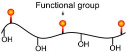
The functional groups can be nonionic such as OH, anionic such as COO−, SO32−, cationic based on N, or the composition may be amphoteric containing both anionic and cationic functional groups. The interactions with the mineral surface, while still the subject of investigation, in general follow similar mechanisms as for collectors, that is, chemical and physical interactions. Initially, natural products and their derivatives were used, but the structural variations are limited and synthetic polymers, which offer the ability to tailor the depressant, are gaining acceptance.
Natural Products
The natural products and derivatives include (Pugh, 1989; Bulatovic, 1999): starch and dextrin (polysaccharides), and carboxylmethylcellulose (CMC); tannin and quebracho; and lignosulfonates. The basic unit of starch (and dextrin) and CMC polymers is shown in Figure 12.23. Dextrins are fragmented starches of lower molecular weight (i.e., n in the Figure is smaller for dextrin compared to starch). Example uses are (Bulatovic, 2007): starch in depression of iron oxide minerals in reverse flotation of silica using amine; dextrin in depression of galena in copper–lead separation; and CMC in depression of silicate minerals in processing Ni-sulfide ores and platinum group (PGM) minerals. For starches and dextrin the functional group appears to be the OH, with adsorption a combination of H-bonding with mineral surface OH groups and possible chemical bridging via Ca2+ and other bivalent ions, which are known to play a role (Figure 12.24(a)) (Bulatovic, 2007). In CMC the functional group is the carboxyl, COO−, which may bond directly with surface metal atoms (Figure 12.24(b)) or again via Ca2+ bridging. Gums are another polysaccharide used largely in non-sulfide systems. Huang et al. (2012) have tested chitosan, a natural polyaminosaccharide, for chalcopyrite–galena separation.


Synthetic Products
These are largely based on polyacrylamide (PAM). The general structure of PAM-based polymers is shown in Figure 12.25. Functional groups include COO−, CH2O− for non-sulfides and CH2S−, CS-NH2 for sulfides. Targets for replacement are sulfur species (e.g., HS) used in Cu–Mo and Cu–Pb separation, which are objectionable reagents on safety and environmental grounds.

12.6.6 Dispersants
Dispersed particles represent a better condition for selective flotation than systems where the particles are aggregated. Several of the depressants also function as dispersants (Nagaraj and Ravishankar, 2007). Rendering the surface hydrophilic means water is held as a hydrated layer on the particle surface, which not only depresses the particle but also makes it less prone to aggregate (to aggregate the hydrated layer on the contacting particles has to be expelled). A reagent used primarily as a dispersant is sodium silicate. The action appears to be related to restoring high negative charge to generate electrostatic repulsion between particles, accomplished through a combination of adsorption of the silicate anion (SiO32−) and removal of metal cations from the surface, sequestering them as insoluble metal silicates. Coating of fine particles on larger particles (“slime coating”) is an example of aggregation. To avoid slime-related problems, in some non-sulfide systems feeds are deslimed by classification (e.g., cycloning, see Chapter 9) with attendant loss of values. Reducing the impact of slimes by controlled dispersion would be preferable.
Dispersants also lower pulp viscosity by reducing particle–particle interactions (Jones and Horsley, 2000; Nagaraj and Ravishankar, 2007). The role of rheology (viscosity) in flotation is reviewed by Farrokhpay (2012), who notes effects in both the pulp and froth zones. Phyllosilicate group minerals pose particular problems (Ndlovu et al., 2014), especially fibrous serpentines which can form tangled mats that entrap bubbles and are buoyed into the froth (Bhambhani et al. 2012). Processing Ni ores hosted in ultramafic rock (i.e., high in fibrous Mg, Fe silicates) is challenged by rheology. Processing fibrous ultramafic ores requires low solids percent in grinding and flotation. A combination of acid attack and grinding to disintegrate the fibers has been shown to produce a pulp more amenable to flotation (Uddin et al., 2011).
12.7 The Importance of pH
It is evident from the foregoing that pulp alkalinity plays an important, though complex, role in flotation, and, in practice, selectivity in complex separations is dependent on a balance between reagent concentrations and pH. In non-sulfide mineral flotation, pH controls surface charge (zeta potential), which can control reactions with ionic collectors and certain regulating agents. Knowing the IEP for the minerals to be separated helps identify the pH window for selective separation. In sulfide mineral flotation with thiol collectors both the ion exchange and electrochemical mechanism teach that increasing pH retards adsorption of the collector and depresses the mineral. Depression occurs at a different pH for each sulfide; for the common sulfides, generally as pH is increased pyrite is depressed first, ca. pH 10, and chalcopyrite last, ca. pH 12 providing the pH window for selective flotation. The critical pH for sulfide depression will depend on the collector concentration. It is generally advisable to keep collector dosage low, at “starvation” levels.
pH Regulators
Flotation is generally carried out in alkaline conditions, with the added advantage that most collectors, including xanthates, are stable under these conditions, and corrosion of cells, pipework, etc., is minimized. Alkalinity is controlled by the addition of lime, sodium carbonate (soda ash), and, to a lesser extent, sodium hydroxide (caustic soda) or ammonia.
Lime is by far the most common alkali used. The choice, however, depends on factors other than strictly pH. Lime by introducing Ca ions into the system is sometimes not the desirable agent. Soda ash can be favored as the carbonate CO32− sequesters calcium and other metal ions from mineral surfaces as precipitates, which both improves particle dispersion and cleans surfaces, making the collector more effective. Espinosa (2011) describes the improved performance substituting soda ash for lime in several Peňoles Cu–Pb–Zn concentrators attributed to avoiding depression by calcium sulfate. Combined use of lime and soda ash may provide an economic compromise (Nesset et al., 1998). Sodium hydroxide is used in iron ore flotation, again to limit effects of calcium, and is employed in bitumen ore processing to aid release of surfactants that contribute to the flotation process.
To reduce pH, sulfuric or sulfurous acids (addition of SO2) are preferred on the basis of cost. Occasionally injecting exhaust CO2 may provide sufficient acidity. At the Niobec concentrator the cleaning section for pyrochlore recovery uses a progressive reduction in pH using hydroflurosilicic and oxalic acids (Biss, 1984).
These pH regulators are often used in significant amounts. For example, lime, although cheaper on a unit weight basis than collectors, the overall cost in sulfide mineral flotation is roughly double that of the collector used, so significant savings can be achieved by the proper choice and use of pH regulators (Fee and Klimpel, 1986).
Lime is used in the form of milk of lime, a suspension of calcium hydroxide particles in a saturated aqueous solution. Lime or soda ash is often added to the slurry prior to flotation to precipitate heavy metal ions from solution. In this sense, the alkali may be considered a deactivator, as some heavy metal ions can activate minerals such as sphalerite and pyrite. Since the heavy metal salts precipitated by the alkali can dissociate to a limited extent and thus allow ions back into solution, cyanide is often used with the alkali to complex them.
Lime can also act as a depressant for pyrite and arsenopyrite when using xanthate collectors. Both the hydroxyl and calcium ions participate in the depressive effect by the formation of mixed films of Fe(OH), FeO(OH), CaSO4, and CaCO3 on the surface, so reducing the adsorption of xanthate. Lime has little such effect with copper minerals, but does depress galena to some extent. In the flotation of galena, therefore, pH control may be effected by the use of soda ash, pyrite and sphalerite being depressed by cyanide.
As was shown earlier, the effectiveness of sodium cyanide and sodium sulfide is governed to such a large extent by pH that these reagents are of scarcely any value in the absence of alkalis. Where cyanide is used as a depressant, the function of the alkali is to control the cyanide ion concentration (Eqs. (12.16) and (12.17)), recognizing for each mineral and given concentration of collector there exists a “critical” cyanide ion concentration above which flotation is impossible. Laboratory results for several minerals are given in Figure 12.26. It is seen that chalcopyrite can be floated from pyrite at pH 7.5 and 30 mg L−1 sodium cyanide and since, of the copper minerals, chalcopyrite lies closest to pyrite relative to the influence of alkali and cyanide, all the copper minerals will float with the chalcopyrite. Thus, by careful choice of pH and cyanide concentration, excellent separations are theoretically possible, although in practice other variables serve to make the separation more difficult. The figure shows that adsorption of xanthate by galena is uninfluenced by cyanide, the alkali alone acting as a depressant.

In addition to controlling the interaction of mineral with collector and regulating agents, pH also controls metal ion speciation in solution and in some cases collector speciation.
Metal Ion Speciation
Multivalent metals ions are hydrolysable, that is, they undergo the following series of reactions:
(12.18)
Species distribution diagrams can be found in a variety of sources (e.g., Miller et al., 2007). The monohydroxy complex and the hydroxide precipitate are active at the mineral surface. Their interaction is revealed by measuring zeta potential, as illustrated in Figure 12.27. Depicted for silica, the same trend holds for many minerals, non-sulfides, and unoxidized sulfides. Three charge reversal pHs are shown: the first corresponds to the IEP of the mineral (there is little interaction with the free ion); the second and third reversals reflect adsorption of the monohydroxy complex and of hydroxide precipitate, the last reversal being the IEP of the hydroxide itself. An explanation for the second charge reversal through interaction with the monohydroxy complex is illustrated in Figure 12.28 for CaOH− and PbOH−. The resulting Ca+ site (Figure 12.28(a)) provides the “bridge” in Figure 12.24(a); and the Pb+ site (Figure 12.28(b)) is sometimes considered responsible for interaction with thiol collectors, giving accidental activation.


The uptake (adsorption) of hydroxide precipitates is an example of heterocoagulation. Over a certain pH range, the particle is negatively charged and the hydroxide precipitate (colloid) is positively charged (IEP ~ pH 10 for the “hydroxide” in Figure 12.27). With sufficient coverage, the particle surface takes on the character of the precipitate, hence the third charge reversal coincides with the hydroxide IEP. In a survey of Cu–Zn concentrators, Mg- and Zn-hydroxy species were identified as promoting particle aggregation (El-Ammouri et al., 2002). Magnesium ions are considered to be the cause of molybdenite depression when floating Cu–Mo ores in seawater at about pH 10 where the hydroxide forms (Nagaraj and Farinato, 2014b; Castro et al., 2014). Figure 12.27 shows clear evidence for possible surface contamination by metal ion species that may influence flotation.
For sulfides the trend in Figure 12.27 is seen for unoxidized surfaces; most sulfides in that state have an IEP ~ pH 2–3, similar to sulfur (Mirnezami et al., 2012). When superficially oxidized, the usual situation, the buildup of oxy-hydroxide species shifts the sulfide IEP to higher pH values. The trend in Figure 12.27 is mimicked for sulfides by progressive increases in the level of oxidation.
Interestingly, the same trends in the presence of hydrolysable cations are seen in the zeta potential of bubbles, which shows the adsorption of metal ion hydrolysis products is quite general (Han et al., 2004).
Collector Speciation
The form of collector can change with pH. An extreme example is the decomposition of xanthate at low pH. In non-sulfide mineral flotation, collectors like fatty acids and fatty amines can be in molecular (undissociated) or ionic form. The reactions are:
(12.19)
(12.20)
In the undissociated form (to the right of the arrow), solubility is low and it is generally the ionic form that acts as a collector. There is a pH where the concentration of ionic and molecular forms is equal, the pKdiss: for fatty acids at pH < pKdiss the molecular form predominates, and for amines at pH > pKdiss the molecular form predominates. For oleate the pKdiss (or pKa)=4.95 and for dodecylamine pKdiss (pKb)=10.63 (Pugh, 1986). The pKdiss is thus an important parameter in the action of these collectors. For example, in Figure 12.9 (Section 12.4.3) for the amine collector, further increase in pH above ca. pH 12 results in rapid decline in flotation as the molecular form becomes dominant. Noting that the maximum flotation rate can often occur at pH near the pKdiss has suggested that combinations of ion and molecular forms, possibly ion-molecular species, can be the active collector in some instances (Pugh, 1986; Rao and Forssberg, 2007). In the fatty acid case, the complex is referred to as an acid-soap. Surface activity (e.g., measured by surface tension depression) is known to be maximum around the pKdiss (Finch and Smith, 1973; Ananthapadmanabhan and Somasundaran, 1988) thus an effect on the frother-related properties of fatty acids and amines can also be expected. Values of Ka and Kb (pK=−log K) are given by Somasundaran and Wang (2006).
12.8 The Importance of Pulp Potential
In sulfide mineral systems the oxidation/reduction conditions play a strong role in selectivity through control of electrochemical reactions. Many of these electrochemical processes are reviewed by Bruckard et al. (2011). The pulp potential of a system is the result of all the anodic (oxidation) and cathodic (reduction) reactions taking place and is difficult to predict. That pulp potential has an impact is understood, however, and can be interpreted from the representation in Figure 12.14. In that example if the potential is too low, below that for xanthate-mineral reaction, then the collector is not adsorbed and the mineral is not floatable. Of course, this may be the desired effect, as in the addition of Na2S to depress chalcopyrite in selective flotation of molybdenite (Poorkani and Banisi, 2005). Represented on the current–potential diagram we would see that the S2− oxidation/O2 reduction potential of the Na2S is lower than that for the adsorption of xanthate, which lowers the pulp potential (i.e., Na2S is a reducing agent). In other words, S2− oxidation is favored over xanthate oxidation (adsorption) and the chalcopyrite is depressed. Molybdenite, being naturally hydrophobic, is not affected by the pulp potential. The action of most inorganic depressants can be interpreted electrochemically (Woods, 2010).
Rather than too low, the pulp potential may be high enough to oxidize the sulfides, producing various depressant hydrophilic oxy-hydroxide surface species. In the Noranda group preflotation aeration was common practice to depress iron sulfides (Konigsmann, et al., 1976). Sulfide mineral slurries can have a high capacity for oxygen, which can be measured by the DO demand, the rate of decrease in DO when the air supply is shut off (Grano, 2010). A measure of the extent of oxidation can be made by extraction with EDTA that readily solubilizes metal oxidation products, but does not attack the sulfide mineral directly (Grano, 2010). Solution analysis before and after EDTA extraction (e.g., by atomic absorption spectroscopy) reveals the metal ions that were held on the surfaces.
The effect of pulp potential, therefore, can be both to promote and depress flotation, depending on the magnitude of the potential. This is illustrated Figure 12.29 for xanthate flotation of Pb (galena) from a sample of Brunswick Mine ore. The pulp potential was controlled in the grinding mill (note reference electrode was Ag/AgCl) and as Ep was increased, first recovery increased, reached a plateau then declined. The increase in recovery is associated with increased adsorption of xanthate via the anodic (oxidation) reaction; the subsequent decrease is associated with production and buildup of oxy-hydroxide oxidation species on the galena surface. Woods (2010) gives examples for other sulfide minerals, which show the same general trend in recovery with pulp potential. In diagnosing low recoveries it would be necessary to establish where on the recovery-pulp potential response you are.

Collectorless Flotation
A certain level of oxidation of sulfide minerals can result in formation of metal deficient or polysulfide sites (Figure 12.4), which can make the mineral floatable without collector. Their formation is an electrochemical process, the anodic reaction being:
(12.21)
with the common electron acceptor again being oxygen. The reaction can continue to eventually form elemental sulfur (S8), which is strongly hydrophobic. Referred to as self-induced or collectorless flotation it has attracted attention (Luttrell and Yoon, 1984; Chander, 1991; Ralston, 1991). Although oxygen is the usual electron acceptor there are others which could substitute, notably iron (Fe3+/Fe2+) ubiquitous in sulfide flotation pulps. In copper activation of sphalerite it is noted that some level of collectorless flotation is achieved, which is attributed to Cu2+ acting as an additional electron acceptor to oxygen and intensifying the oxidation (Lascelles and Finch, 2002). The addition of sulfide ions can also bring about collectorless flotation (Yoon, 1981). Pyrrhotite is in effect a metal deficient iron sulfide (Pratt et al., 1994) and naturally has polysulfides on the surface and often exhibits collectorless flotation.
Collectorless flotation can be demonstrated in the plant practice, but there is usually little incentive to exploit as there is no easy way to determine if collectorless flotation will be robust to ore changes and collector addition removes that concern (Leroux et al., 1994).
In the disintegration of fibers involving strong acid attack mentioned in Section 12.6.6 with respect to a novel processing route for ultramafic Ni ores, the oxidizing conditions produced by the concentrated sulfuric acid rendered the pentlandite (and pyrrhotite) collectorlessly floatable. At the same time the amount of MgSO4 put into solution provided an ionic strength sufficient to replace the need for frother (see Section 12.5.4). The process, therefore, gave a technically interesting collectorless-and-frotherless flotation system.
Galvanic Interaction
Recalling from Section 12.4.4 that sulfides have different rest potential values means that when they are in contact with each other in electrolyte (i.e., process water) it will induce galvanic interaction. Iwasaki and co-workers (Adam and Iwasaki, 1984; Nakazawa and Iwasaki, 1985) were among the first to consider the implications of galvanic interactions in flotation.
To illustrate galvanic interaction consider three materials in a grinding mill, in order of decreasing rest potential: pyrite, galena, and mild steel. The associated current–potential diagram is shown in Figure 12.30. In this case, each anodic reaction is matched with its own cathodic (oxygen reduction) reaction. The mixed potential at IA=IC establishes that the highest anodic current is contributed by oxidation of the steel, and that the highest cathodic current is contributed by reduction of oxygen on the surface of pyrite, with galena oxidation/reduction reactions in between. The physical picture is illustrated in Figure 12.31: the pyrite draws electrons from both steel and galena accelerating their oxidation.


The result of the galvanic interactions depicted in Figure 12.31 includes lowering of DO (consumed by accepting electrons) and release of metal ions both with implications for flotation. The lowering of DO in the grinding mill discharge may retard reaction with collector and reduce floatability. Aeration in a bank of flotation cells may restore the DO level necessary for flotation but there may be a case for preflotation aeration. In reactor–separator flotation cells (Section 12.13.3) with short retention time, ensuring that the DO level is sufficient for flotation is an important precaution.
Oxidation promoted by galvanic interaction releases Pb and Fe ions into the pulp. (Recent work has shown that galvanic interactions, especially in the presence of pyrite, promote formation of hydrogen peroxide (H2O2), which further accelerates oxidation rates (Nooshabadi et al., 2013).) The released Pb2+ ions may accidentally activate other minerals. Acting on the suspicion that Pb2+ ions were activating pyrite, Brunswick Mine installed a flotation stage between the autogenous (AG) mill and the ball mill to remove galena before the further size reduction (i.e., increase in galena surface area) added to the release of more Pb2+ ions. The result was increased pyrite rejection from the bulk Cu–Pb concentrate (Finch et al., 2007a). Addition of reducing agents into the grinding circuit to reduce galena oxidation was another successful option at another plant (Finch et al., 2007a).
Oxidation of the steel (i.e., corrosion) releases a series of hydrophilic iron oxy-hydroxide species into the pulp that adsorb indiscriminately and act as general depressants. Trying to limit contamination of flotation pulps by iron species has led to the use of inert (non-steel) media in stirred regrind mills (Pease et al., 2006), and is an argument in favor of AG milling (Bruckard et al., 2011). One reason raising pH is common practice is to retard release of iron species from the steel through suppression of galvanic interactions by inhibiting the reduction of oxygen on the pyrite (in the example in Figure 12.31). Replacing forged steel media by corrosion-resistant high chrome media at Ernest Henry Mining permitted the pH to be lowered in the roughers from 10.6 to 9.6 without release of excessive iron corrosion species (as determined by low Fe extraction by EDTA). The copper and gold metallurgy was essentially unchanged with the reduction in lime consumption valued at $700,000 (Kirkwood et al., 2014). Of course this needs to more than offset any increase in grinding media costs. The conversion was the result of extensive laboratory testing using the Magotteau grinding mill which permits close control over pulp chemistry. Details on laboratory testing to simulate plant chemical conditions are given in Grano (2010).
The importance of simulating the plant chemical environment when conducting laboratory tests is illustrated by investigations into cases of apparent accidental activation of sphalerite by cyanide in Cu–Zn ores (Rao et al., 2011). At low pulp potential, copper leached into solution is held as a cupro-cyanide complex (Section 12.6.3), which is not only stable but with Cu in the +1 state means that there is no exchange with Zn2+ ions in the sphalerite surface lattice. If the pulp potential is raised, however, the cupro-cyanide is oxidized to cupric cyanide, a reaction that both increases leaching of copper and puts Cu in the +2 state, making exchange with Zn2+ ions in the sphalerite lattice now possible. The implication is that if laboratory grinding is with steel media giving low pulp potential then this accidental activation mechanism is not observed; but if the plant grinding circuit is AG then pulp potential is higher than in the lab experience and accidental activation of sphalerite may occur. Espinosa (2011) reviewing plant practices at several Cu–Zn operations reported sphalerite activation by cyanide. In tests using the Magotteau mill to control pulp chemistry, he established the role of oxidation in the use of cyanide causing accidental activation of sphalerite. Alternative depressants such as sulfoxy species may have to be substituted if this cyanide activation problem is encountered.
The impact of galvanic interactions can be seen in ore stockpiles and reclaimed pillars at the end of mine life. Pyrite in weathered (i.e., oxidized) ore will still be relatively untarnished and bright, while other sulfides like sphalerite may disintegrate to the touch.
Mild steel usually has the lowest rest potential and is oxidized by most sulfide minerals. There are exceptions. In milling matte at Vale Base Metals’ Sudbury operation the steel balls are not corroded. The sulfide minerals in the matte are chalcocite (Cu2S) and heazelwoodite (Ni3S2) and these have a lower rest potential than the steel (Bozkurt et al., 1994); in this case the steel is “protected” and accelerates oxidation of the minerals.
Galvanic interactions are not necessarily detrimental as the preceding may imply. Considering that xanthate adsorption is an oxidation reaction, the adsorption of xanthate on galena in contact with pyrite is promoted, while at the same time the surface of pyrite hosts the formation of hydroxyl ions which generate hydrophilic (depressant) Fe oxy-hydroxide products. The galvanic contact thus promotes selective flotation of galena over pyrite. In the Galvanox™ process pyrite is deliberately added to a second sulfide to enhance leaching rates, an example where galvanic effects are exploited to advantage. There are options to include the Galvanox™ process in combination with flotation to form an integrated circuit (Dixon et al., 2007).
Use of Nitrogen
There is occasional reference to the potential for gases other than air in sulfide mineral flotation, nitrogen being the logical candidate based on cost (Johnson, 1988). The action of nitrogen substituting for air as flotation gas can be interpreted as reducing galvanic interactions. It has been shown that nitrogen promotes xanthate flotation of pyrite relative to other sulfide minerals (Martin et al., 1989; Xu et al., 1995). The postulated mechanism is that the nitrogen breaks the galvanic interaction between sphalerite and pyrite, which suppresses the formation of oxy-hydroxides on the pyrite surface. The removal of these hydrophilic species both eliminates a pyrite depressant and opens sites for adsorption of collector.
A commercial process for pyrite reverse flotation from sphalerite concentrate employs heat and SO2 conditioning. The combination appears to first produce strong oxidizing conditions that destroy the Cu–xanthate on the sphalerite surface and ties up the Cu as an oxide, and finally leads to a low pulp potential that favors pyrite flotation. The use of nitrogen helps maintain the low potential, thus permitting less aggressive conditioning (Xu et al. 1995; Grano, 2010). In pyrite reverse flotation from Pb concentrate in Brunswick Mine’s Pb upgrading circuit, heating alone (to ca. 75°) appears to be sufficient (Martin et al., 2000); this could in part be due to heating lowering the DO sufficient to suppress galvanic contact and thus prevent the oxy-hydroxide from forming on the pyrite surface.
Experiments on pyrite alone show that pyrite is depressed by nitrogen, explained by the rest potential being too low to support formation of dixanthogen (Figure 12.18). When pyrite is in combination with other sulfides this is not the case. The nature of the hydrophobic species on the pyrite at low pulp potential remains the subject of investigation (Miller et al., 2006). The situation with the other major iron sulfide mineral, pyrrhotite, is different. Using nitrogen pyrrhotite is effectively depressed in separation from pentlandite. In this case it appears that the collectorless flotation of pyrrhotite due to oxidation of the surface polysulfides to elemental sulfur is suppressed by the lowered potential with nitrogen (Finch et al., 1996, 2007a).
Practical applications of nitrogen must meet the challenge of maintaining a nitrogen atmosphere in face of the many opportunities for air (oxygen) to enter the system, via open balls mills and hydrocyclones being two examples. This ingress of oxygen has hampered commercial attempts in the promising use of nitrogen to depress pyrrhotite away from pentlandite. One possible solution is to enclose flotation cells and recycle the air which leads to an atmosphere enriched in nitrogen by taking advantage of the high oxygen demand of sulfide pulps. A small supply of nitrogen would still be needed to replace the volume of oxygen consumed to maintain ambient air pressure inside the cell. Another possibility is to take advantage of locations where a nitrogen stream is available, for example, off-gas from oxygen production. The patented N2TEC technology implemented at Lone Tree mine used such an off-gas source of nitrogen and reported improved selective recovery of Au-bearing pyrite (Simmons, 1997). Where nitrogen is commonly used is in chalcopyrite–molybdenite separation, where it both reduces side oxidation reactions that consume the chalcopyrite depressants, NaHS/Na2S, and helps maintain a low pulp potential, which depresses chalcopyrite (Aravena, 1987; Poorkani and Banisi, 2005).
To take advantage of pulp potential in control of mineral separations requires measurement. Measurement of Ep is more problematic than measurement of pH. Traditionally, it is measured using a noble metal (usually platinum but sometimes gold) as the sensing electrode with calomel (Hg/Hg2Cl2) or silver/silver chloride (Ag/AgCl) as reference electrodes. The sensing electrode needs to be inert and designed to include contributions to the pulp potential from the particles—it is the potential at the mineral/solution interface that matters in flotation. Sensing electrodes are prone to fouling and need close attention (Chander, 2003). An example of successful Ep measurement is in control of NaSH/Na2S additions in chalcopyrite–molybdenite separation. Here the noble metal sensing electrode becomes coated with sulfur and responds to the sulfide ions in solution (Woods, 2010).
Control of potential through reagents is often not easy, the systems being buffered to change. The possibility of direct control through design of an electrochemical cell, successfully used at the laboratory scale, is an area of research for industrial application (Panayotov and Panayotova, 2013).
12.9 Flotation Kinetics
The engineering approach is to consider flotation as a rate process by analogy with chemical reaction kinetics (Amelunxen and Runge, 2014). The reactants in flotation are the bubble and particle and the product is the bubble–particle aggregate. From this standpoint, the rate of flotation will depend on a number of factors: concentration of particles and bubbles, frequency of collision, efficiency of particle attachment upon collision, and stability of the attachment. Making some assumptions simplifies development of a model, the key ones being: the reaction follows first order, the bubble concentration does not vary, and colliding particles can always find space on a bubble to attach. Under these conditions the rate of disappearance of particle mass (−dW/dt) in a flotation cell is proportional to the particle mass in the cell (W). Mathematically, this is expressed as, where k is the flotation rate constant:
(12.22)
The rate constant k lumps all the unmeasured variables and becomes an engineering measure of floatability; the higher the floatability the higher the rate constant, making k a widely used parameter.
To solve Eq. (12.22) requires the nature of the particle transport through the cell to be known. The simplest case is batch flotation, where all particles are treated as having the same residence time.
12.9.1 Batch Flotation
The solution is given by integrating from time 0 to t when mass in the cell decreases from W0 to W:
(12.23)
(12.24)
(12.25)
Rearranging to give the more familiar expression for recovery, where R=(W0 – W)/W0 (R on a fractional basis) gives:
(12.26)
We will return to the batch Eq. (12.26) in “flotation testing” (Section 12.12).
12.9.2 Continuous Flotation
In continuously operating units, transport behavior can be determined by a tracer test, as illustrated in Figure 12.32(a).