
3 Camcorder: power and audio facilities
An important preliminary note:
The layout, labelling and position on the camcorder body of individual control panels, and the switches thereon, varies between each make and model, although each individual camcorder should have the functions described herein. Some of the functions, and the manner in which they operate, may also be altered through menu settings within the camcorder itself.
However, for the exact operational placement and switch labelling, and the parameters relating to menu functions, you must consult the relevant camcorder handbook.
Power
Most location operations rely on battery power for the camcorder. Broadcast models are normally run from 12 V rechargeable batteries, and have an operating range in the region of 10–14 V. The majority also have an external power supply connection in the form of a 4-pin XLR socket (Figure 3.1), and you can run them from a mains supply using a suitable transformer. The LCD display on the side of the camcorder often provides a rough indication of the voltage level, or the charge status of the battery (Figure 3.2). (See also Batteries and run time, below.)
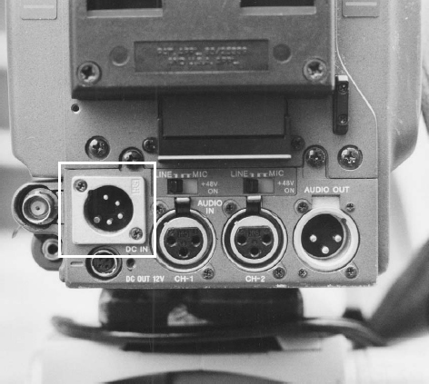
Figure 3.1 4-pin 12 V XLR power input on camcorder rear panel
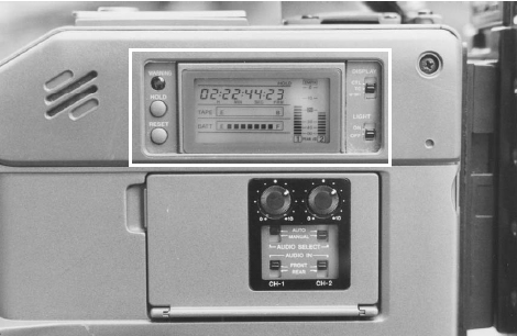
Figure 3.2 LCD display on the side of the camcorder, showing the charge status of the battery
On broadcast models, the power switch is usually located on the side body panel, and mounted in a horizontal operating position (Figure 3.3). One point to be aware of, on the front camera operational panel, there may be a switch position (often labelled ‘VTR’) for a save mode (Figure 3.4). In this condition, the camcorder is on, but the tape is not in contact with the record heads, in other words, this is a ‘head saving’ mode (this may instead be labelled camera/VTR in which case, the tape is not in contact with the heads in the camera position). It also has the unfortunate side-effect of not providing a sound feed to the camcorder monitoring facilities. Always make sure this is switched to the St/by (VTR) position which, although it will put the heads in contact with the tape, will provide you with your sound monitoring facilities. But if the cameraman is intent on minimizing the head wear, do remember to return it to the save position when you are satisfied with your levels.
Inputs
Most camcorders have XLR sockets for their sound inputs (Figure 3.5), although some of the smaller DV and mini DV models may have phono or 3.5 mm (mini) jack sockets (Figure 3.6). The advantage of the XLR connector is that it locks into position, and so cannot be pulled out accidentally, unlike the phono, with which this is a distinct possibility. Plus it is of a more robust and rugged construction, thus less prone to mechanical damage and general wear and tear with everyday use.
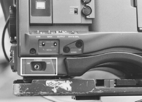
Figure 3.3 Camcorder power switch
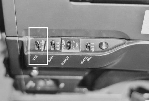
Figure 3.4 Camcorder VTR save/standby switch
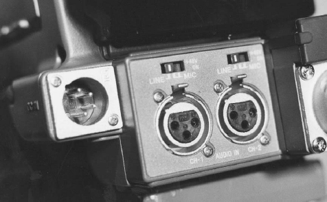
Figure 3.5 Two 3-pin XLR inputs on camcorder rear panel
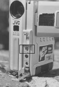
Figure 3.6 Mini DV camcorder with mini-jack socket mic input on front panel
Most camcorders have two sound inputs (normally referred to as ‘channel’ inputs), usually sited towards the bottom of the rear panel (Figure 3.7), and two soundtracks (upon which the audio is recorded). There are some models which provide four soundtracks, but accessing all four can often prove difficult and time-consuming, and not all edit suites are configured to accommodate them. Moreover, you may find that if you do use all four tracks, for example on DV systems, then the recorded sound will almost certainly be below broadcast standard in quality. Therefore, in this handbook we will only consider a camcorder to have two sound tracks available for recording purposes.
Sound output
Some camcorders provide outputs from either or both channels, which you may find useful for transcription recording (Figures 3.7 and 3.8). But if you do wish to use this for transcription purposes, note that most audio cassette recorders have mic level input, whilst the outputs on the camcorder are line level, i.e. amplified (see Section 4, Camcorder: track selection and magnetic recording). This means you will have to obtain/make up a connecting lead with a 60 dB pad (attenuation) to drop the level back down to mic voltage.

Figure 3.7 3-pin XLR inputs at rear of camcorder together with 3 pin XLR audio output beside them
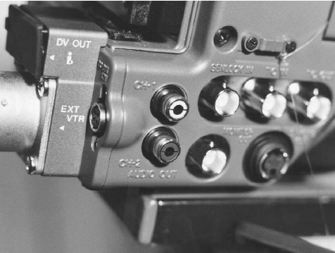
Figure 3.8 Sound output (on phono sockets)
You may also find that some companies have modified their audio monitoring facilities to utilize the sound output from this socket/s, assuming that there is a signal present during the recording process. This will almost certainly mean that the headphones that you need to use in conjunction with this facility will have a more robust connector than the mini-jack, lending an increased reliability to this method of monitoring. However, in use, it does mean that the audio monitor level controls on the side of the camcorder do not affect this output, and that there must be some other form of level control available for your headphones (the modification to use this facility will probably take the form of a lead/s which plugs into the camcorder output socket/s and has a ‘bodge-box’ of some form with at least one, if not more, headphone sockets with volume control).
You should also be aware that using this facility in this way means that the feed to the on-board loudspeaker is not cut (since you have not plugged any headphones into the mini-jack monitoring socket on the side of the camcorder). Therefore you will almost certainly have to ensure that you turn these controls down to zero/off, in order to ensure that there is no breakthrough or disturbance from this source.
If you own your equipment and wish to utilize this method of audio monitoring, do make sure that the model of camcorder you have provides you with the sound output on the relevant socket/s during recording. (See also Section 7, Camcorder: external facilities – sound monitoring, for the mainstream information on monitoring the audio feed for normal recording purposes.)
Phantom power
On most camcorders this facility is switched above the XLR input socket (Figure 3.9), although on others it may be sited on the side panel of switches below the LCD display, or within the menu functions (see also Section 4, Camcorder: track selection and magnetic recording). Only turn it on if you are using a mic which needs this form of powering. Although the term ‘phantom’ implies that it shouldn't affect anything other than a mic which requires this facility, it is possible that a cable, wiring, connection, or other circuit fault could lead to a hum or buzz on the soundtrack if it's left on unnecessarily.
Batteries and run time
One of the most vexing questions you are likely to face is, ‘How long does each battery last?’ Judging by their external appearance, you have no way of telling, unless the battery has a readout of its charge status/voltage on its casing (I've only come across a couple of models that provide this facility). Once plugged/connected to the camcorder, there may be a display on the LCD readout (Figure 3.2) showing the charge status, but this cannot be relied upon unless you have used that particular battery/camcorder combination before, and have confidence in the display's accuracy. When the batteries are new, and the camcorder has been correctly set internally (or via its menus) for the maximum battery voltage in use, then the display will almost certainly be accurate, but after the equipment has been in the field for any length of time, well, who knows?

Figure 3.9 Phantom power switch (above each XLR input)
Moreover, battery run time will be affected by the amount of power drain it's subjected to, and the functions it's required to operate. A quick run down of these will give you some idea of the rate at which you may deplete it's capacity, depending on how often you use:
![]() picture processing and viewfinder
picture processing and viewfinder
![]() zoom
zoom
![]() auto functions (iris, focus, etc.)
auto functions (iris, focus, etc.)
![]() phantom power
phantom power
![]() run to record
run to record
![]() cue (tally) lights on
cue (tally) lights on
![]() LCD light on
LCD light on
![]() on-camera lamp
on-camera lamp
![]() power for external device from DC out on camcorder (e.g. radio mic receiver).
power for external device from DC out on camcorder (e.g. radio mic receiver).
Hence there's no easy answer to the question of run time, and only experience with the individual items of equipment can be your judge. However, it is worth noting that having each individual battery labelled/numbered will save time if you suspect a fault. There is nothing more annoying than arriving back at base after a day's shoot, and not being able to recall which of half a dozen batteries had a problem, since they all look the same!
Warning! Should any battery have been dropped during the shoot, make sure that you put it to one side (and label or mark it accordingly as ‘suspect’) to be checked by a competent authority. Although it may still deliver power, and even appear to charge as per normal on its regular charger, it may actually be dangerous to use. Depending on the internal design/construction, individual cells within batteries are prone to fracture under external pressure, and in certain circumstances may overheat (and combust) if they, or their associated circuitry, have been damaged.