Day 24 Switching Technologies and VLAN Concepts
CCNA 640-802 Exam Topics
![]() Describe enhanced switching technologies (VTP, RSTP, VLAN, PVSTP, 802.1Q).
Describe enhanced switching technologies (VTP, RSTP, VLAN, PVSTP, 802.1Q).
![]() Describe how VLANs create logically separate networks and the need for routing between them.
Describe how VLANs create logically separate networks and the need for routing between them.
![]() Configure, verify, and troubleshoot RSTP operation.
Configure, verify, and troubleshoot RSTP operation.
Key Points
Virtual local-area networks (VLANs) are a switching technology used to improve network performance by separating large broadcast domains into smaller ones. VLAN trunks provide a way for one physical interface to transport multiple VLANs. The IEEE 802.1Q trunking protocol is the recommended frame tagging method to use on trunk links. In larger networks where there are many switches to manage, VLAN Trunking Protocol (VTP) provides a way to automatically update switches with new or modified VLAN information. Spanning Tree Protocol (STP) and its variants allow redundant switched networks without worrying about switching loops. Although STP can be tweaked with a few commands, it runs by default and might not need any adjustment at all.
VLAN Concepts
Although a switch “out of the box” is configured to have only one VLAN, normally a switch will be configured to have two or more VLANs. Doing so creates multiple broadcast domains by putting some interfaces into one VLAN and other interfaces into other VLANs.
Reasons for using VLANs include the following:
![]() Grouping users by department instead of by physical location
Grouping users by department instead of by physical location
![]() Segmenting devices into smaller LANs to reduce processing overhead for all devices on the LAN
Segmenting devices into smaller LANs to reduce processing overhead for all devices on the LAN
![]() Reducing the workload of STP by limiting a VLAN to a single access switch
Reducing the workload of STP by limiting a VLAN to a single access switch
![]() Enforcing better security by isolating sensitive data to separate VLANs
Enforcing better security by isolating sensitive data to separate VLANs
![]() Separating IP voice traffic from data traffic
Separating IP voice traffic from data traffic
Benefits of using VLANs include the following:
![]() Security: Sensitive data can be isolated to one VLAN, separating it from the rest of the network.
Security: Sensitive data can be isolated to one VLAN, separating it from the rest of the network.
![]() Cost reduction: Cost savings result from less need for expensive network upgrades and more efficient use of existing bandwidth and uplinks.
Cost reduction: Cost savings result from less need for expensive network upgrades and more efficient use of existing bandwidth and uplinks.
![]() Higher performance: Dividing flat Layer 2 networks into multiple logical broadcast domains reduces unnecessary traffic on the network and boosts performance.
Higher performance: Dividing flat Layer 2 networks into multiple logical broadcast domains reduces unnecessary traffic on the network and boosts performance.
![]() Broadcast storm mitigation: VLAN segmentation prevents a broadcast storm from propagating throughout the entire network.
Broadcast storm mitigation: VLAN segmentation prevents a broadcast storm from propagating throughout the entire network.
![]() Ease of management and troubleshooting: A hierarchical addressing scheme groups network addresses contiguously. Because a hierarchical IP addressing scheme makes problem components easier to locate, network management and troubleshooting are more efficient.
Ease of management and troubleshooting: A hierarchical addressing scheme groups network addresses contiguously. Because a hierarchical IP addressing scheme makes problem components easier to locate, network management and troubleshooting are more efficient.
Traffic Types
A key factor for VLAN deployment is understanding the traffic patterns and the various traffic types in the organization. Table 24-1 lists the common types of network traffic that you should evaluate before placing devices and configuring VLANs.

Types of VLANs
Some VLAN types are defined by the type of traffic they support; others are defined by the specific functions they perform. The principal VLAN types and their descriptions follow:
![]() Data VLAN: Configured to carry only user-generated traffic, ensuring that voice and management traffic is separated from data traffic.
Data VLAN: Configured to carry only user-generated traffic, ensuring that voice and management traffic is separated from data traffic.
![]() Default VLAN: All the ports on a switch are members of the default VLAN when the switch is reset to factory defaults. The default VLAN for Cisco switches is VLAN 1. VLAN 1 has all the features of any VLAN, except that you cannot rename it and you cannot delete it. It is a security best practice to restrict VLAN 1 to serve as a conduit only for Layer 2 control traffic (for example, CDP or VTP), supporting no other traffic.
Default VLAN: All the ports on a switch are members of the default VLAN when the switch is reset to factory defaults. The default VLAN for Cisco switches is VLAN 1. VLAN 1 has all the features of any VLAN, except that you cannot rename it and you cannot delete it. It is a security best practice to restrict VLAN 1 to serve as a conduit only for Layer 2 control traffic (for example, CDP or VTP), supporting no other traffic.
![]() Black hole VLAN: A security best practice is to define a black hole VLAN to be a dummy VLAN distinct from all other VLANs defined in the switched LAN. All unused switch ports are assigned to the black hole VLAN so that any unauthorized device connecting to an unused switch port will be prevented from communicating beyond the switch to which it is connected.
Black hole VLAN: A security best practice is to define a black hole VLAN to be a dummy VLAN distinct from all other VLANs defined in the switched LAN. All unused switch ports are assigned to the black hole VLAN so that any unauthorized device connecting to an unused switch port will be prevented from communicating beyond the switch to which it is connected.
![]() Native VLAN: This VLAN type serves as a common identifier on opposing ends of a trunk link. A security best practice is to define a native VLAN to be a dummy VLAN distinct from all other VLANs defined in the switched LAN. The native VLAN is not used for any traffic in the switched network unless legacy bridging devices happen to be present in the network, or a multiaccess interconnection exists between switches joined by a hub.
Native VLAN: This VLAN type serves as a common identifier on opposing ends of a trunk link. A security best practice is to define a native VLAN to be a dummy VLAN distinct from all other VLANs defined in the switched LAN. The native VLAN is not used for any traffic in the switched network unless legacy bridging devices happen to be present in the network, or a multiaccess interconnection exists between switches joined by a hub.
![]() Management VLAN: A VLAN defined by the network administrator as a means to access the management capabilities of a switch. By default, VLAN 1 is the management VLAN. It is a security best practice to define the management VLAN to be a VLAN distinct from all other VLANs defined in the switched LAN. You do so by configuring and activating a new VLAN interface.
Management VLAN: A VLAN defined by the network administrator as a means to access the management capabilities of a switch. By default, VLAN 1 is the management VLAN. It is a security best practice to define the management VLAN to be a VLAN distinct from all other VLANs defined in the switched LAN. You do so by configuring and activating a new VLAN interface.
![]() Voice VLANs: The voice VLAN feature enables switch ports to carry IP voice traffic from an IP phone. The network administrator configures a voice VLAN and assigns it to access ports. Then when an IP phone is connected to the switch port, the switch sends CDP messages that instruct the attached IP phone to send voice traffic tagged with the voice VLAN ID.
Voice VLANs: The voice VLAN feature enables switch ports to carry IP voice traffic from an IP phone. The network administrator configures a voice VLAN and assigns it to access ports. Then when an IP phone is connected to the switch port, the switch sends CDP messages that instruct the attached IP phone to send voice traffic tagged with the voice VLAN ID.
Voice VLAN Example
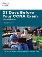
Figure 24-1 shows an example of using one port on a switch to connect a user’s IP phone and PC. The switch port is configured to carry data traffic on VLAN 20 and voice traffic on VLAN 150. The Cisco IP Phone contains an integrated three-port 10/100 switch to provide the following dedicated connections:
![]() Port 1 connects to the switch or other VoIP device.
Port 1 connects to the switch or other VoIP device.
![]() Port 2 is an internal 10/100 interface that carries the IP phone traffic.
Port 2 is an internal 10/100 interface that carries the IP phone traffic.
![]() Port 3 (access port) connects to a PC or other device.
Port 3 (access port) connects to a PC or other device.
The traffic from the PC5 attached to the IP Phone passes through the IP Phone untagged. The link between S2 and the IP Phone act as a modified trunk to carry both the tagged voice traffic and the untagged data traffic.
Trunking VLANs
A VLAN trunk is an Ethernet point-to-point link between an Ethernet switch interface and an Ethernet interface on another networking device, such as a router or a switch, carrying the traffic of multiple VLANs over the singular link. A VLAN trunk allows you to extend the VLANs across an entire network. A VLAN trunk does not belong to a specific VLAN; rather, it serves as a conduit for VLANs between switches. Figure 24-2 shows a small switched network with a trunk link between S1 and S2 carrying multiple VLAN traffic.

When a frame is placed on a trunk link, information about the VLAN it belongs to must be added to the frame. This is accomplished by using IEEE 802.1Q frame tagging. When a switch receives a frame on a port configured in access mode and destined for a remote device via a trunk link, the switch takes apart the frame and inserts a VLAN tag, recalculates the frame check sequence (FCS), and sends the tagged frame out the trunk port. Figure 24-3 shows the 802.1Q tag inserted in an Ethernet frame.

The VLAN tag field consists of a 16-bit Type field called the EtherType field and a Tag control information field. The EtherType field is set to the hexadecimal value of 0x8100. This value is called the tag protocol ID (TPID) value. With the EtherType field set to the TPID value, the switch receiving the frame knows to look for information in the Tag control information field. The Tag control information field contains the following:
![]() 3 bits of user priority: Used to provide expedited transmission of Layer 2 frames, such as voice traffic.
3 bits of user priority: Used to provide expedited transmission of Layer 2 frames, such as voice traffic.
![]() 1 bit of Canonical Format Identifier (CFI): Enables Token Ring frames to be carried across Ethernet links easily.
1 bit of Canonical Format Identifier (CFI): Enables Token Ring frames to be carried across Ethernet links easily.
![]() 12 bits of VLAN ID (VID): VLAN identification numbers.
12 bits of VLAN ID (VID): VLAN identification numbers.
Although 802.1Q is the recommended method for tagging frames, you should be aware of Cisco’s legacy trunking protocol called Inter-Switch link (ISL). You must specify the trunking protocol used on trunk interfaces on all Cisco Catalyst switches except the 29xx series.
Dynamic Trunking Protocol
Dynamic Trunking Protocol (DTP) is a Cisco proprietary protocol that negotiates both the status of trunk ports as well as the trunk encapsulation of trunk ports. DTP manages trunk negotiation only if the port on the other switch is configured in a trunk mode that supports DTP. A switch port on a Cisco Catalyst switch supports a number of trunking modes. The trunking mode defines how the port negotiates using DTP to set up a trunk link with its peer port. The following is a brief description of each trunking mode:
![]() If the switch is configured with the switchport mode trunk command, the switch port periodically sends DTP messages to the remote port advertising that it is in an unconditional trunking state.
If the switch is configured with the switchport mode trunk command, the switch port periodically sends DTP messages to the remote port advertising that it is in an unconditional trunking state.
![]() If the switch is configured with the switchport mode trunk dynamic auto command, the local switch port advertises to the remote switch port that it is able to trunk but does not request to go to the trunking state. After a DTP negotiation, the local port ends up in trunking state only if the remote port trunk mode has been configured so that the status is on or desirable. If both ports on the switches are set to auto, they do not negotiate to be in a trunking state. They negotiate to be in the access mode state.
If the switch is configured with the switchport mode trunk dynamic auto command, the local switch port advertises to the remote switch port that it is able to trunk but does not request to go to the trunking state. After a DTP negotiation, the local port ends up in trunking state only if the remote port trunk mode has been configured so that the status is on or desirable. If both ports on the switches are set to auto, they do not negotiate to be in a trunking state. They negotiate to be in the access mode state.
![]() If the switch is configured with the switchport mode dynamic desirable command, the local switch port advertises to the remote switch port that it is able to trunk and asks the remote switch port to go to the trunking state. If the local port detects that the remote has been configured as on, desirable, or auto mode, the local port ends up in trunking state. If the remote switch port is in the nonegotiate mode, the local switch port remains as a nontrunking port.
If the switch is configured with the switchport mode dynamic desirable command, the local switch port advertises to the remote switch port that it is able to trunk and asks the remote switch port to go to the trunking state. If the local port detects that the remote has been configured as on, desirable, or auto mode, the local port ends up in trunking state. If the remote switch port is in the nonegotiate mode, the local switch port remains as a nontrunking port.
![]() If the switch is configured with the switchport nonegotiate command, the local port is then considered to be in an unconditional trunking state. Use this feature when you need to configure a trunk with a switch from another switch vendor.
If the switch is configured with the switchport nonegotiate command, the local port is then considered to be in an unconditional trunking state. Use this feature when you need to configure a trunk with a switch from another switch vendor.
Table 24-2 summarizes the results of DTP negotiations based on the different DTP configuration commands.

VTP Concepts
The name for Cisco’s proprietary VLAN Trunking Protocol (VTP) can be confusing. VTP does not provide a method for trunking between devices. Instead, VTP is a Layer 2 messaging protocol that maintains VLAN configuration consistency by managing the additions, deletions, and name changes of VLANs across networks. VTP helps with VLAN management and although it makes the configuration and troubleshooting of VLANs easier, it is not required.
The benefits of VTP include the following:
![]() VLAN configuration consistency across the network
VLAN configuration consistency across the network
![]() Accurate tracking and monitoring of VLANs
Accurate tracking and monitoring of VLANs
![]() Dynamic reporting of added VLANs across a network
Dynamic reporting of added VLANs across a network
Figure 24-4 shows an example of how VTP messages can be sent between the VTP server and VTP clients.

Notice in the figure that the shaded area is named VTP Domain CCNA. A VTP domain is one switch or several interconnected switches that share VTP advertisements. A switch can be in only one VTP domain. A router or Layer 3 switch defines the boundary of each domain.
VTP Modes
VTP operates in one of three modes:
![]() Server: The server is where VLANs can be created, deleted, or renamed for the domain. VTP servers advertise VLAN information to other switches in the same VTP domain and store the VLAN information in NVRAM.
Server: The server is where VLANs can be created, deleted, or renamed for the domain. VTP servers advertise VLAN information to other switches in the same VTP domain and store the VLAN information in NVRAM.
![]() Client: You cannot create, change, or delete VLANs on a VTP client. A switch reset deletes the VLAN information. You must configure a switch to change its VTP mode to client.
Client: You cannot create, change, or delete VLANs on a VTP client. A switch reset deletes the VLAN information. You must configure a switch to change its VTP mode to client.
![]() Transparent: VTP transparent mode switches forward VTP advertisements to VTP clients and VTP servers, but do not originate or otherwise implement VTP advertisements. VLANs that are created, renamed, or deleted on a VTP transparent mode switch are local to that switch only.
Transparent: VTP transparent mode switches forward VTP advertisements to VTP clients and VTP servers, but do not originate or otherwise implement VTP advertisements. VLANs that are created, renamed, or deleted on a VTP transparent mode switch are local to that switch only.
VTP Operation
VTP advertisements are sent by the server every 5 minutes over the default VLAN using a multicast frame. A configuration revision number included in the frame is used by all VTP clients and servers to determine if there has been a change in the VLAN database. Figure 24-5 illustrates VTP operation.

Figure 24-5 begins with all switches having the same VLAN configuration revision number, meaning that they have the same VLAN configuration database; this means that all switches know about the same VLAN numbers and VLAN names. The process begins with each switch knowing that the current configuration revision number is 3. The steps shown in Figure 24-5 are as follows:
-
Someone configures a new VLAN on the VTP server.
-
The VTP server updates its VLAN database revision number from 3 to 4.
-
The server sends VTP update messages out its trunk interfaces, stating revision number 4.
-
The two VTP client switches notice that the updates list a higher revision number (4) than their current revision numbers (3).
-
The two client switches update their VLAN databases based on the server’s VTP updates.
VTP defines three types of messages:
![]() Summary advertisement: Sent every 5 minutes by the server; it lists the revision number, domain name, and other information, but no VLAN information.
Summary advertisement: Sent every 5 minutes by the server; it lists the revision number, domain name, and other information, but no VLAN information.
![]() Subset advertisement: Follows a summary advertisement if something has changed in the VLAN database, indicated by a new larger revision number.
Subset advertisement: Follows a summary advertisement if something has changed in the VLAN database, indicated by a new larger revision number.
![]() Advertisement request message: Allows a switch to immediately request VTP messages from a neighboring switch as soon as a trunk comes up.
Advertisement request message: Allows a switch to immediately request VTP messages from a neighboring switch as soon as a trunk comes up.
VTP Pruning
By default, a trunk connection carries traffic for all VLANs in the VTP management domain; however, every switch might not have ports assigned to every VLAN. VTP pruning uses VLAN advertisements to determine when a trunk connection is flooding VLAN traffic needlessly.
Pruning means that the appropriate switch trunk interfaces do not flood frames in that VLAN. Figure 24-6 shows an example, with the dashed-line rectangles denoting the trunks from which VLAN 10 has been automatically pruned.

STP Concepts and Operation
One of the key characteristics of a well-built communications network is that it is resilient. This means that the network needs to be able to handle a device or link failure through redundancy. A redundant topology can eliminate a single point of failure by using multiple links, multiple devices, or both. Spanning Tree Protocol (STP) is used to prevent loops in a redundant switched network.
Without STP, redundancy in the switched network would introduce the following issues:
![]() Broadcast storms: Each switch floods broadcasts endlessly, called a broadcast storm.
Broadcast storms: Each switch floods broadcasts endlessly, called a broadcast storm.
![]() Multiple frame transmission: Multiple copies of unicast frames may be delivered to the destination causing unrecoverable errors.
Multiple frame transmission: Multiple copies of unicast frames may be delivered to the destination causing unrecoverable errors.
![]() MAC database instability: Instability in the content of the MAC address table results from copies of the same frame being received on different ports of the switch.
MAC database instability: Instability in the content of the MAC address table results from copies of the same frame being received on different ports of the switch.
STP is an IEEE committee standard defined as 802.1d. STP places certain ports in the blocking state so that they do not listen to, forward, or flood data frames. STP creates a tree that ensures there is only one path to each network segment at any one time. Then, if any segment experiences a disruption in connectivity, STP rebuilds a new tree by activating the previously inactive, but redundant, path.
The algorithm used by STP chooses the interfaces that should be placed into a Forwarding State. For any interfaces not chosen to be in a Forwarding State, STP places the interfaces in Blocking State.
Switches exchange STP configuration messages every 2 seconds by default using a multicast frame called the bridge protocol data unit (BPDU). One of the pieces of information included in the BPDU is the bridge ID (BID).
The BID is unique to each switch and is composed of a priority value (2 bytes) and the bridge MAC address (6 bytes). The default priority is 32,768. The root bridge is the bridge with the lowest BID. Therefore, if the default priority value is not changed, the switch with the lowest MAC address will become root.
To start the process, the STP algorithm elects a root switch and places all working interfaces on the root switch in Forwarding State. Then, each nonroot switch considers one of its ports to have the least administrative cost between itself and the root switch. STP places this least-root-cost interface, called that switch’s root port (RP), in Forwarding State. Finally, many switches can attach to the same Ethernet segment. So the switch with the lowest administrative cost from itself to the root bridge, as compared with the other switches attached to the same segment, is placed in Forwarding State. The lowest-cost switch on each segment is called the designated bridge, and that bridge’s interface, attached to that segment, is called the designated port (DP). Switches that are not designated bridges have their nondesignated ports placed in Blocking State.
Table 24-3 summarizes the reasons STP place a port in Forwarding or Blocking State.

Port bandwidth is used to determine the cost to reach the root bridge. Table 24-4 lists the default port costs defined by IEEE, which had to be revised with the advent of 10 Gbps ports.

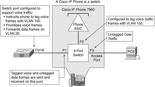
STP uses the four states shown in Figure 24-7 as a port transitions from Blocking to Forwarding.
A fifth state, Disabled, occurs either when a network administrator manually disables the port or a security violation disables the port.
RSTP Concepts and Operation
IEEE improved the convergence performance of STP from 50 seconds to less than 10 seconds with its definition of Rapid STP (RSTP) in the standard 802.1w. RSTP is identical to STP in the following ways:
![]() It elects the root switch using the same parameters and tiebreakers.
It elects the root switch using the same parameters and tiebreakers.
![]() It elects the root port on nonroot switches with the same rules.
It elects the root port on nonroot switches with the same rules.
![]() It elects designated ports on each LAN segment with the same rules.
It elects designated ports on each LAN segment with the same rules.
![]() It places each port in either Forwarding or Blocking State, although RSTP calls the Blocking State the Discarding State.
It places each port in either Forwarding or Blocking State, although RSTP calls the Blocking State the Discarding State.
The main changes with RSTP can be seen when changes occur in the network. RSTP acts differently on some interfaces based on what is connected to the interface.
![]() Edge-Type Behavior and PortFast: RSTP improves convergence for edge-type connections by immediately placing the port in Forwarding State when the link is physically active.
Edge-Type Behavior and PortFast: RSTP improves convergence for edge-type connections by immediately placing the port in Forwarding State when the link is physically active.
![]() Link-Type Shared: RSTP doesn’t do anything differently from STP on link-type shared links. However, because most of the links between switches today are not shared, but are typically full-duplex point-to-point links, it doesn’t matter.
Link-Type Shared: RSTP doesn’t do anything differently from STP on link-type shared links. However, because most of the links between switches today are not shared, but are typically full-duplex point-to-point links, it doesn’t matter.
![]() Link-Type Point-to-Point: RSTP improves convergence over full-duplex links between switches. RSTP recognizes the loss of the path to the root bridge, through the root port, in 3 times the Hello timer, or 6 seconds with a default Hello timer value of 2 seconds. So RSTP recognizes a lost path to the root much more quickly.
Link-Type Point-to-Point: RSTP improves convergence over full-duplex links between switches. RSTP recognizes the loss of the path to the root bridge, through the root port, in 3 times the Hello timer, or 6 seconds with a default Hello timer value of 2 seconds. So RSTP recognizes a lost path to the root much more quickly.
RSTP uses different terminology to describe port states. Table 24-5 lists the port states for RSTP and STP.

RSTP removes the need for Listening State and reduces the time required for Learning State by actively discovering the network’s new state. STP passively waits on new BPDUs and reacts to them during the Listening and Learning States. With RSTP, the switches negotiate with neighboring switches by sending RSTP messages. The messages enable the switches to quickly determine whether an interface can be immediately transitioned to a Forwarding State. In many cases, the process takes only a second or two for the entire RSTP domain.
RSTP also adds three more port roles to the root port and designated port roles defined in STP. Table 24-6 lists and defines the port roles.

Configuring and Verifying STP
By default, all Cisco switches use STP without any configuration by the network administrator. However, because STP runs on a per-VLAN basis—creates a separate spanning-tree instance for every VLAN—you can take advantage of several options to load-balance traffic across redundant links.
PVST+, PVRST, and MIST
802.1d does not support a spanning-tree instance for each VLAN because VLANs did not exist when the standard was first introduced. Cisco switches include a proprietary feature called Per-VLAN Spanning Tree Plus (PVST), which creates a separate instance of STP for each VLAN.
Again, when IEEE introduced 802.1w, there still was no support for multiple instances of STP. So Cisco implemented another proprietary solution called either Rapid Per-VLAN Spanning Tree (RPVST) or Per-VLAN Rapid Spanning Tree (PVRST). Later, IEEE created the 802.1s standard called Multiple Instances of Spanning Tree (MIST). Table 24-7 summarizes these three options for using multiple spanning trees to load balance traffic.

Configuring and Verifying the BID
Regardless of the which per-VLAN Spanning Tree is used, two main configuration options can be used to achieve load-balancing—bridge ID and port cost manipulation. The bridge ID influences the choice of root switch and can be configured per VLAN. Each interface’s (per-VLAN) STP cost to reach the root influences the choice of designated port on each LAN segment. Because PVST requires that a separate instance of spanning tree run for each VLAN, the BID field is required to carry VLAN ID (VID) information. This is accomplished by reusing a portion of the Priority field as the extended system ID to carry a VID.
Table 24-8 summarizes the default settings for both BID and port costs.

Figure 24-8 shows a simple three-switch STP topology.

The network administrator wants to ensure that S1 is always the root bridge and S2 is the backup root bridge. The following commands achieve this objective.
S1(config)# spanning-tree vlan 1 root primary
S2(config)# spanning-tree vlan 1 root secondary
The primary keyword sets the priority to 24576 or to the next 4096 increment value below the lowest bridge priority detected on the network.
The secondary keyword sets the priority to 28672, assuming the rest of the network is set to the default priority of 32768.
Alternatively, the network administrator can configure the priority value in increments of 4096 between 0 and 65536 using the following command.
S1(config)# spanning-tree vlan 1 priority 24576
S2(config)# spanning-tree vlan 1 priority 28672
Note These commands changed the priority values only for VLAN 1. Additional commands must be entered for each VLAN to take advantage of load balancing.
To verify the current spanning-tree instances and root bridges, use the show spanning-tree command as shown in Example 24-1.

Because an extended system ID is used in the BID, the value of the priority includes the addition of the VLAN ID. So, a priority of 24576 plus a VLAN of 1 results in an priority output of 24577.
PortFast
To speed up convergence for access ports when they become active, you can use Cisco’s proprietary PortFast technology. After PortFast is configured and a port is activated, the port immediately transitions from the blocking state to the forwarding state. Example 24-2 shows the interface command to configure PortFast.
Alternatively, you can configure the global command spanning-tree portfast default, which enables PortFast by default on all access ports.
Configuring RSTP
Remember, STP is the default operation of Cisco switches. To change to RSTP and PVRST, use a single global command on all switches: spanning-tree mode rapid-pvst.
Troubleshooting STP
STP runs by default on switches and rarely causes problems in small- to medium-sized networks. However, you might encounter STP troubleshooting problems on the exam. Use the following steps to analyze an STP problem:
Step 1 Determine the root switch.
Step 2 For each nonroot switch, determine its one root port (RP) and cost to reach the root switch through that RP.
Step 3 For each segment, determine the designated port (DP) and the cost advertised by the DP onto that segment.
The information requested in each of the steps can be obtained from variations of the show spanning-tree command.