
CHAPTER 42
Using Space Warps
Creating and binding Space Warps to objects
Understanding the various Space Warp types
Working with Space Warps and particle systems
Space Warps sound like a special effect from a science fiction movie, but actually they are nonrenderable objects that let you affect another object in many unique ways to create special effects.
You can think of Space Warps as the unseen forces that control the movement of objects in the scene such as gravity, wind, and waves. Several Space Warps, such as Push and Motor, deal with dynamic simulations and can define forces in real-world units. Some Space Warps can deform an object's surface; others provide the same functionality as certain modifiers.
Space Warps are particularly useful when combined with particle systems. This chapter includes some examples of Space Warps that have been combined with particle systems.
Creating and Binding Space Warps
Space Warps are a way to add forces to the scene that can act on an object. Space Warps are not renderable and must be bound to an object to have an effect. A single Space Warp can be bound to several objects, and a single object can be bound to several Space Warps.
In many ways, Space Warps are similar to modifiers, but modifiers typically apply to individual objects, whereas Space Warps can be applied to many objects at the same time and are applied using World Space Coordinates. This ability to work with multiple objects makes Space Warps the preferred way to alter particle systems and to add forces to dynamic hair and cloth systems.
Creating a Space Warp
Space Warps are found in the Create ![]() Space Warps menu, which opens the Space Warps category (the icon is three wavy lines) in the Create panel. From the subcategory drop-down list, you can select from several different subcategories. Each subcategory has buttons to enable several different Space Warps, or you can select them using the Create
Space Warps menu, which opens the Space Warps category (the icon is three wavy lines) in the Create panel. From the subcategory drop-down list, you can select from several different subcategories. Each subcategory has buttons to enable several different Space Warps, or you can select them using the Create ![]() Space Warps menu command. To create a Space Warp, click a button or select a menu option and then click and drag in a viewport.
Space Warps menu command. To create a Space Warp, click a button or select a menu option and then click and drag in a viewport.
When a Space Warp is created, a gizmo is placed in the scene. This gizmo can be transformed as other objects can: by using the standard transformation buttons. The size and position of the Space Warp gizmo often affect its results. After a Space Warp is created, it affects only the objects to which it is bound.
Binding a Space Warp to an object
![]() A Space Warp's influence is felt only by its bound objects, so you can selectively apply gravity only to certain objects. The Bind to Space Warp button is on the main toolbar next to the Unlink button. After clicking the Bind to Space Warp button, drag from the Space Warp to the object to which you want to link it or vice versa.
A Space Warp's influence is felt only by its bound objects, so you can selectively apply gravity only to certain objects. The Bind to Space Warp button is on the main toolbar next to the Unlink button. After clicking the Bind to Space Warp button, drag from the Space Warp to the object to which you want to link it or vice versa.
All Space Warp bindings appear in the Modifier Stack. You can use the Edit Modifier Stack dialog box to copy and paste Space Warps between objects.
Some Space Warps can be bound only to certain types of objects. Each Space Warp has a Supports Objects of Type rollout that lists the supported objects. If you're having trouble binding a Space Warp to an object, check this rollout to see whether the object is supported.
Understanding Space Warp Types
Just as many different types of forces exist in nature, many different Space Warp types exist. These appear in several different subcategories, based on their function. The subcategories are Forces, Deflectors, Geometric/Deformable, Modifier-Based, and Particles & Dynamics.
Note
The Particles & Dynamics subcategory includes a Vector Field button that is used with biped crowds, discussed in Bonus Chapter 8, “Creating Character Crowds.”
Force Space Warps
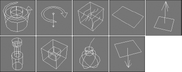
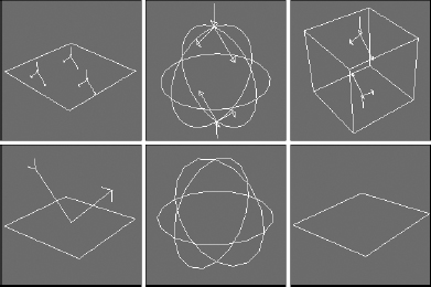
The Forces subcategory of Space Warps is mainly used with particle systems and dynamic simulations. Space Warps in this subcategory include Motor, Vortex, Path Follow, Displace, Wind, Push, Drag, PBomb, and Gravity. Figure 42.1 shows the gizmos for these Space Warps.
Motor
The Motor Space Warp applies a rotational torque to objects. This force accelerates objects radially instead of linearly. The Basic Torque value is a measurement of torque in newton-meters, foot-pounds, or inch-pounds.
The On Time and Off Time options set the frames where the force is applied and disabled, respectively. Many of the Space Warps have these same values.
FIGURE 42.1 The Force Space Warps: Motor, Vortex, Path Follow, Displace, Wind, Push, Drag, PBomb, and Gravity
The Feedback On option causes the force to change as the object's speed changes. When this option is off, the force stays constant. You can also set Target Revolution units in revolutions per hour (RPH), revolutions per minute (RPM), or revolutions per second (RPS), which is the speed at which the force begins to change if the Feedback option is enabled. The Reversible option causes the force to change directions if the Target Speed is reached, and the Gain value is how quickly the force adjusts.
The motor force can also be adjusted with Periodic Variations, which cause the motor force to increase and then decrease in a regular pattern. You can define two different sets of Periodic Variation parameters: Period 1, Amplitude 1, Phase 1; and Period 2, Amplitude 2, Phase 2.
For particle systems, you can enable and set a Range value. The Motor Space Warp doesn't affect particles outside this distance. At the bottom of the Parameters rollout, you can set the size of the gizmo icon. You can find this same value for all Space Warps.
Figure 42.2 shows the Motor Space Warp twisting the particles being emitted from the Super Spray particle system in the direction of the icon's arrow.
Push
The Push Space Warp accelerates objects in the direction of the Space Warp's icon from the large cylinder to the small cylinder. Many of the parameters for the Push Space Warp are similar to those for the Motor Space Warp. Using the Parameters rollout, you can specify the force Strength in units of newtons or pounds.
The Feedback On option causes the force to change as the object's speed changes, except that it deals with Target Speed instead of Target Revolution like the Motor Space Warp does.
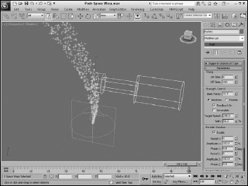
The push force can also be set to include Periodic Variations that are the same as with the Motor Space Warp. Figure 42.3 shows the Push Space Warp pushing the particles being emitted from the Super Spray particle system.
FIGURE 42.2 You can use the Motor Space Warp to apply a twisting force to particles and dynamic objects.
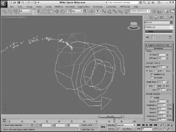
FIGURE 42.3 You can use the Push Space Warp to apply a controlled force to particles and dynamic objects.
Vortex
You can use the Vortex Space Warp on particle systems to make particles spin around in a spiral like going down a whirlpool. You can use the Timing settings to set the beginning and ending frames where the effect takes place.
You can also specify Taper Length and Taper values, which determine the shape of the vortex. Lower Taper Length values wind the vortex tighter, and the Taper Curve values can range between 1.0 and 4.0 and control the ratio between the spiral diameter at the top of the vortex versus the bottom of the vortex.
The Axial Drop value specifies how far each turn of the spiral is from the adjacent turn. The Damping value sets how quickly the Axial Drop value takes effect. The Orbital Speed is how fast the particles rotate away from the center. The Radial Pull value is the distance from the center of each spiral path that the particles can rotate. If the Unlimited Range option is disabled, then Range and Falloff values are included for each setting. You can also specify whether the vortex spins clockwise or counterclockwise.
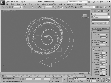
Figure 42.4 shows a Vortex Space Warp being bound to a particle system.
FIGURE 42.4 You can use the Vortex Space Warp to force a particle system into a spiral like a whirlpool.
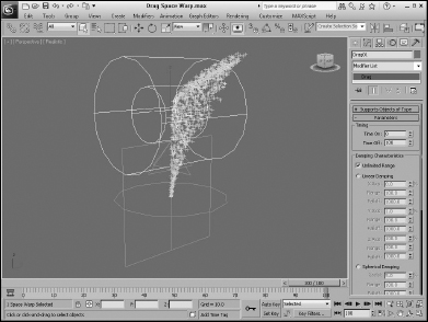
Drag
Drag is another common force that can be simulated with a Space Warp. The Drag Space Warp can be Linear, Spherical, or Cylindrical. This Space Warp causes particle velocity to be decreased, such as when simulating air resistance or fluid viscosity. Use the Time On and Time Off options to set the frame where the Space Warp is in effect.
For each of the Damping shape types—Linear, Spherical, and Cylindrical—you can set the drag, which can be along each axis for the Linear shape or in the Radial, Tangential, and Axial direction for the Spherical and Cylindrical shapes. If the Unlimited Range option is not selected, then the Range and Falloff values are available.
Figure 42.5 shows a Drag Space Warp surrounding a particle system. Notice how the particles are slowed and moved to the side as they pass through the Drag space warp.
FIGURE 42.5 You can use the Drag Space Warp to slow the velocity of particles.
PBomb
The PBomb (particle bomb) Space Warp was designed specifically for the PArray particle system, but it can be used with any particle system. To blow up an object with the PBomb Space Warp, create an object, make it a PArray emitter, and then bind the PBomb Space Warp to the PArray.
You can find more information on the PArray particle system in Chapter 41, “Creating Particles and Particle Flow.”
Basic parameters for this Space Warp include three blast symmetry types: Spherical, Cylindrical, and Planar. You can also set the Chaos value as a percentage.
In the Explosion Parameters section, the Start Time is the frame where the explosion takes place, and the Duration defines how long the explosion forces are applied. The Strength value is the power of the explosion.
A Range value can be set to determine the extent of the explosion. It is measured from the center of the Space Warp icon. If the Unlimited Range option is selected, the Range value is disabled. The Linear and Exponential options change how the explosion forces die out. The Range Indicator option displays the effective blast range of the PBomb.
Figure 42.6 shows a box selected as an emitter for a PArray. The PBomb is bound to the PArray and not to the box object. The Speed value for the PArray has been set to 0, and the Particle Type is set to Fragments. Notice that the PBomb's icon determines the center of the blast.
FIGURE 42.6 You can use the PBomb Space Warp with the PArray particle system to create explosions.
Path Follow
The Path Follow Space Warp causes particles to follow a path defined by a spline. The Basic Parameters rollout for this Space Warp includes a Pick Shape Object button for selecting the spline path to use. You can also specify a Range value or the Unlimited Range option. The Range distance is measured from the path to the particle.
Cross-Reference
The Path Follow Space Warp is similar to the Path Constraint, which is discussed in Chapter 22, “Animating with Constraints and Simple Controllers.”
In the Motion Timing section, the Start Frame value is the frame where the particles start following the path, the Travel Time is the number of frames required to travel the entire path, and the Last Frame is where the particles no longer follow the path. There is also a Variation value to add some randomness to the movement of the particles.
The Basic Parameters rollout also includes a Particle Motion section with two options for controlling how the particles proceed down the path: Along Offset Splines and Along Parallel Splines. The first causes the particles to move along splines that are offset from the original, and the second moves all particles from their initial location along parallel path splines. The Constant Speed option makes all particles move at the same speed.
Also in the Particle Motion section is the Stream Taper value. This value is the amount by which the particles move away from the path over time. Options include Converge, Diverge, or Both. Converging streams move all particles closer to the path, and diverging streams do the opposite. The Stream value is the number of spiral turns that the particles take along the path. This swirling motion can be Clockwise, Counterclockwise, or Bidirectional. The Seed value determines the randomness of the stream settings.
Figure 42.7 shows a Path Follow Space Warp bound to a Super Spray particle system. A Helix shape has been selected as the path.
Gravity
The Gravity Space Warp adds the effect of gravity to a scene. This causes objects to accelerate in the direction specified by the Gravity Space Warp, like the Wind Space Warp. The Parameters rollout includes Strength and Decay values. Additional options make the gravity planar or spherical. You can turn on the Range Indicators to display a plane or sphere where the gravity is half its maximum value.
Wind
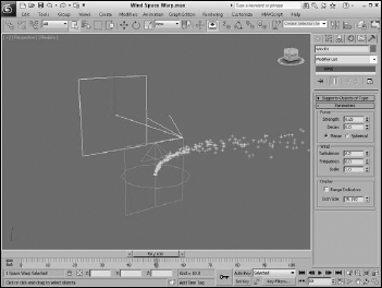
The Wind Space Warp causes objects to accelerate. The Parameters rollout includes Strength and Decay values. Additional options make the gravity planar or spherical. The Turbulence value randomly moves the objects in different directions, and the Frequency value controls how often these random turbulent changes occur. Larger Scale values cause turbulence to affect larger areas, but smaller values are wilder and more chaotic.
You can turn on the Range Indicators just like the Gravity Space Warp. Figure 42.8 shows the Wind Space Warp pushing the particles being emitted from a Super Spray particle system.
FIGURE 42.7 A Path Follow Space Warp bound to an emitter from the Super Spray particle system and following a Helix path
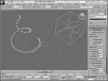
FIGURE 42.8 You can use the Wind Space Warp to blow particles and dynamic objects.
Displace
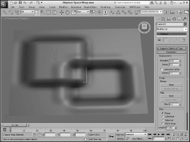
The Displace Space Warp is like a force field: It pushes objects and is useful when applied to a particle system. It can also work on any deformable object in addition to particle systems. The strength of the displacement can be defined with Strength and Decay values or with a grayscale bitmap.
The Strength value is the distance that the geometry is displaced and can be positive or negative. The Decay value causes the displacement to decrease as the distance increases. The Luminance Center is the grayscale point where no displacement occurs; any color darker than this center value is moved away, and any brighter areas move closer.
The Bitmap and Map buttons let you load images to use as a displacement map; the amount of displacement corresponds with the brightness of the image. A Blur setting blurs the image. You can apply these maps with different mapping options, including Planar, Cylindrical, Spherical, and Shrink Wrap. You can also adjust the Length, Width, and Height dimensions and the U, V, and W Tile values.
Cross-Reference
The Displace Space Warp is similar in function to the Displace modifier. The Displace modifier is discussed in Chapter 17, “Adding Material Details with Maps.”
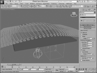
Figure 42.9 shows two Displace Space Warps with opposite Strength values.
FIGURE 42.9 The Displace Space Warp can raise or indent the surface of a patch grid.
Deflector Space Warps
The Deflectors subcategory of Space Warps includes POmniFlect, SOmniFlect, UOmniFlect, Deflector, SDeflector, and UDeflector. You use them all with particle systems. This category includes several different types of deflectors starting with P, S, and U. The difference between these types is their shape. P-type (planar) deflectors are box shaped, S-type (spherical) deflectors are spherical, and U-type (universal) deflectors include a Pick Object button that you can use to select any object as a deflector.
Figure 42.10 shows the icons for each of these Space Warps. All the P-type deflectors are in the first column, the S-type deflectors are in the second column, and the U-type deflectors are in the third column.
Tip
When you use deflector objects, the number of polygons makes a big difference. The deflector object uses the normal to calculate the bounce direction, so if the deflector object includes lots of polygon faces, then the system slows way down. A solution to this, especially if you—re using a simple plane deflector, because all its polygon normals are the same, anyway, is to use a simplified proxy object as the deflector and hide it so the particles look like they are hitting the complex object.
FIGURE 42.10 The Deflector Space Warps: POmniFlect, SOmniFlect, UOmniFlect, UDeflector, SDeflector, and Deflector
POmniFlect, SOmniFlect, and UOmniFlect
The POmniFlect Space Warp is a planar deflector that defines how particles reflect and bounce off other objects. The SOmniFlect Space Warp is just like the POmniFlect Space Warp, except that it is spherical in shape. The UOmniFlect Space Warp is another deflector, but this one can assume the shape of another object using the Pick Object button in the Parameters rollout. Its Parameters rollout includes a Timing section with Time On and Time Off values and a Reflection section.
The difference between this type of Space Warp and the other deflector Space Warps is the addition of refraction. Particles bound to this Space Warp can be refracted through an object. The values entered in the Refraction section of the Parameters rollout change the velocity and direction of a particle. The Refracts value is the percentage of particles that are refracted. The Pass Vel (velocity) is the amount that the particle speed changes when entering the object; a value of 100 maintains the same speed. The Distortion value affects the angle of refraction; a value of 0 maintains the same angle, and a value of 100 causes the particle to move along the surface of the struck object. The Diffusion value spreads the particles throughout the struck object. You can vary each of these values by using its respective Variation value.
Note
If the Refracts value is set to 100 percent, no particles are available to be refracted.
You can also specify Friction and Inherit Velocity values. In the Spawn Effects Only section, the Spawns and Pass Velocity values control how many particle spawns are available and their velocity upon entering the struck object. Figure 42.11 shows each of these Space Warps bound to a Super Spray particle system. The Reflect percentage for each of the Space Warps is set to 50, and the remaining particles are refracted through the Space Warp's plane. Notice that the particles are also reflecting off the opposite side of the refracting object.
Deflector, SDeflector, and UDeflector
The Deflector and SDeflector Space Warps are simplified versions of the POmniFlect and SOmniFlect Space Warps. Their parameters include values for Bounce, Variation, Chaos, Friction, and Inherit Velocity. The UDeflector Space Warp is a simplified version of the UOmniFlect Space Warp. It has a Pick Object button for selecting the object to act as the deflector and all the same parameters as the SDeflector Space Warp.
Geometric/Deformable Space Warps
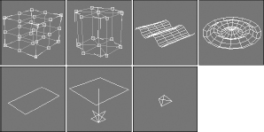
You use Geometric/Deformable Space Warps to deform the geometry of an object. Space Warps in this subcategory include FFD (Box), FFD (Cyl), Wave, Ripple, Displace, Conform, and Bomb. These Space Warps can be applied to any deformable object. Figure 42.12 shows the icons for each of these Space Warps.
FIGURE 42.11 The POmniFlect, SOmniFlect, and UOmniFlect Space Warps reflecting and refracting particles emitted from the Super Spray particle system
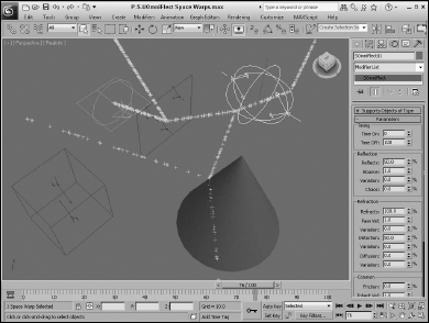
FIGURE 42.12 The Geometric/Deformable Space Warps: FFD (Box), FFD (Cyl), Wave, Ripple, Displace, Conform, and Bomb
FFD (Box) and FFD (Cyl)
The FFD (Box) and FFD (Cyl) Space Warps show up as a lattice of control points in the shape of a box and a cylinder; you can select and move the control points that make up the Space Warp to deform an object that is bound to the Space Warp. The object is deformed only if the bound object is within the volume of the Space Warp.
These Space Warps have the same parameters as the modifiers with the same name found in the Modifiers ![]() Free Form Deformers menu. The difference is that the Space Warps act in World coordinates and aren—t tied to a specific object. This allows a single FFD Space Warp to affect multiple objects.
Free Form Deformers menu. The difference is that the Space Warps act in World coordinates and aren—t tied to a specific object. This allows a single FFD Space Warp to affect multiple objects.
Cross-Reference
To learn about the FFD (Box) and FFD (Cyl) modifiers, see Chapter 11, “Introducing Modifiers and Using the Modifier Stack.”
To move the control points, select the Space Warp object, open the Modify panel, and select the Control Points subobject, which lets you alter the control points individually.
FFD Select modifier
The FFD Select modifier is another unique selection modifier. It enables you to select a group of control point subobjects for the FFD (Box) or the FFD (Cyl) Space Warps and apply additional modifiers to the selection. When an FFD Space Warp is applied to an object, you can select the Control Points subobjects and apply modifiers to the selection. The FFD Select modifier lets you select a different set of control points for a different modifier.
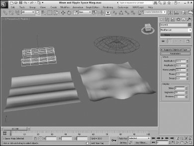
Wave and Ripple
The Wave and Ripple Space Warps create linear and radial waves in the objects to which they are bound. Parameters in the rollout help define the shape of the wave. Amplitude 1 is the wave's height along the X-axis, and Amplitude 2 is the wave's height along its Y-axis. The Wave Length value defines how long each wave is. The Phase value determines how the wave starts at its origin. The Decay value sets how quickly the wave dies out. A Decay value of 0 maintains the same amplitude for the entire wave.
The Sides (Circles) and Segments values determine the number of segments for the X- and Y-axes. The Division value changes the icon's size without altering the wave effect. Figure 42.13 shows a Wave Space Warp applied to a simple Box primitive. Notice that the Space Warp icon is smaller than the box, yet it affects the entire object.
Note
Be sure to include enough segments in the bound object, or the effect won—t be visible.
FIGURE 42.13 The Wave and Ripple Space Warps applied to a patch grid object
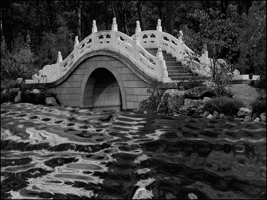
Tutorial: Creating pond ripples
For this tutorial, you position a patch object so it aligns with a background image and apply the Ripple Space Warp to it.
To add ripples to a pond, follow these steps:
- Open the Pond ripple.max file from the Chap 42 directory on the CD.
This file includes a background image of a bridge matched to a patch grid where the pond is located with a reflective material assigned to it.
Tip
If you—re having trouble locating the patch grid, press F3 to switch to Wireframe mode.
- Select the Create
 Space Warps Geometric/Deformable Ripple menu command. Drag in the Perspective view to create a Space Warp object. In the Parameters rollout, set the Amplitudes to 2 and the Wave Length to 30.
 - Click the Bind to Space Warp button, and drag from the patch object to the Space Warp.
Figure 42.14 shows the resulting image.
FIGURE 42.14 A ripple in a pond produced using the Ripple Space Warp
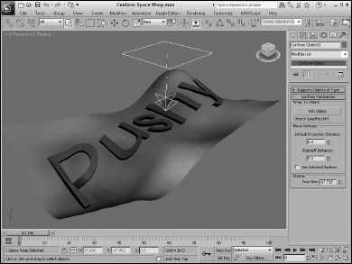
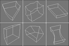
Conform
The Conform Space Warp pushes all object vertices until they hit another target object called the Wrap To Object, or until they—ve moved a preset amount. The Conform Parameters rollout includes a Pick Object button that lets you pick the Wrap To Object. The object vertices move no farther than this Wrap To Object.
You can also specify a Default Projection Distance and a Standoff Distance. The Default Projection Distance is the maximum distance that the vertices move if they don—t intersect with the Wrap To Object. The Standoff Distance is the separation amount maintained between the Wrap To Object and the moved vertices. Another option, Use Selected Vertices, moves only a subobject selection.
Cross-Reference
The Conform Space Warp is similar in function to the Conform compound object that is covered in Chapter 27, “Working with Compound Objects.”
Figure 42.15 shows some text being deformed with the Conform Space Warp. A warped quad patch has been selected as the Wrap To object.
FIGURE 42.15 The Conform Space Warp wraps the surface of one object around another object.
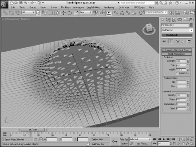
Bomb
The Bomb Space Warp causes an object to explode from its individual faces. The Strength value is the power of the bomb and determines how far objects travel when exploded. The Spin value is the rate at which the individual pieces rotate. The Falloff value defines the boundaries of faces affected by the bomb. Object faces beyond this distance remain unaffected. You must select Falloff On for the Falloff value to work.
The Min and Max Fragment Size values set the minimum and maximum number of faces caused by the explosion.
The Gravity value determines the strength of gravity and can be positive or negative. Gravity always points toward the world's Z-axis. The Chaos value can range between 0 and 10 to add variety to the explosion. The Detonation value is the number of the frame where the explosion should take place, and the Seed value alters the randomness of the event. Figure 42.16 shows a frame of an explosion produced by the Bomb Space Warp.
FIGURE 42.16 The Bomb Space Warp causes an object to explode.
Note
The Bomb Space Warp is seen over time. At frame 0, the object shows no effect.
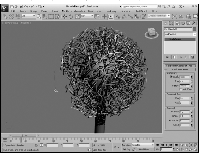
Tutorial: Blowing a dandelion puff
You can use Space Warps with other types of objects besides particle systems. The Scatter object, for example, can quickly create many unique objects that can be controlled by a Space Warp. In this tutorial, you create a simple dandelion puff that can blow away in the wind.
To create and blow away a dandelion puff, follow these steps:
- Open the Dandelion puff.max file from the Chap 42 directory on the CD.
This file includes a sphere covered with a Scatter compound object representing the seeds of a dandelion.
- Select the Create Space Warps Geometric/Deformable Bomb menu command. Click in the Front viewport, and position the Bomb icon to the left and slightly below the dandelion object. In the Bomb Parameters rollout, set the Strength to 10, the Spin to 0.5, the Min and Max Fragment Size values to 24, the Gravity to 0.2, and the Chaos to 2.0.
This is the total number of faces included in the dandelion object.
- Click the Bind to Space Warp button on the main toolbar, and drag from the dandelion object to the Space Warp. Then press the Play button to see the animation.
Figure 42.17 shows one frame of the dandelion puff being blown away.
FIGURE 42.17 You can use Space Warps on Scatter objects as well as particle systems.
Modifier-Based Space Warps
Modifier-Based Space Warps produce the same effects as many of the standard modifiers, but because they are Space Warps, they can be applied to many objects simultaneously. Space Warps in this subcategory include Bend, Noise, Skew, Taper, Twist, and Stretch, as shown in Figure 42.18. All Modifier-Based Space Warp gizmos are simple box shapes. The parameters for all Modifier-Based Space Warps are identical to the modifiers (found in the Parametric Deformers category) of the same name. These Space Warps don—t include a Supports Objects of Type rollout because they can be applied to all objects.
Cross-Reference
For details on the Bend, Noise, Skew, Taper, Twist, and Stretch modifiers and their parameters, see Chapter 11, “Introducing Modifiers and Using the Modifier Stack.”
FIGURE 42.18 The Modifier-Based Space Warps: Bend, Noise, Skew, Taper, Twist, and Stretch
These Space Warps include a Gizmo Parameters rollout with values for the Length, Width, and Height of the gizmo. You can also specify the deformation decay. The Decay value causes the Space Warp's effect to diminish with distance from the bound object.
You can reposition the Modifier-Based Space Warp's gizmo as a separate object, but the normal modifiers require that you select the gizmo subobject to reposition it. Unlike modifiers, Space Warps don—t have any subobjects.
Combining Particle Systems with Space Warps
To conclude this chapter, you—ll look at some examples that use Space Warps along with particle systems. With all these Space Warps and their various parameters combined with particle systems, the possibilities are endless. These examples are only a small representation of what is possible.
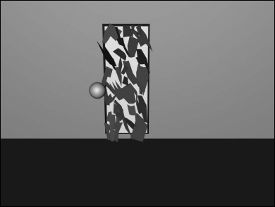
Tutorial: Shattering glass
When glass shatters, it is very chaotic, sending pieces in every direction. For this tutorial, you shatter a glass mirror on a wall. The wall keeps the pieces from flying off, and most pieces fall straight to the floor.
To shatter glass, follow these steps:
- Open the Shattering glass.max file from the Chap 42 directory on the CD.
This file includes a simple mirror created from patch grid objects. The file also includes a simple sphere that is animated striking the mirror.
- Select the Create Particles PArray menu command. Then drag in the Front viewport to create the PArray icon. In the Basic Parameters rollout, click the Pick Object button and select the first patch object. In the Viewport Display section, select the Mesh option. In the Particle Generation rollout, set the Speed and Divergence to 0. Also set the Emit Start to 30 and the Life value to 100, so it matches the last frame. In the Particle Type rollout, select the Object Fragments option, and set the Thickness to 1.0. Then in the Object Fragment Controls section, select the Number of Chunks option with a Minimum value of 30. In the Rotation and Collision rollout, set the Spin Time to 100 and the Variation to 50.
These settings cause the patch to emit 30 object fragments with a slow, gradual rotation.
- Select the Space Warps category button, and choose the Forces subcategory from the drop-down list. Click the PBomb button, and create a PBomb Space Warp in the Top view; then center it above the Mirror patch. In the Modify panel, set the Blast Symmetry option to Spherical with a Chaos value of 50 percent. Set the Start Time to 30 with a Strength value of 0.2. Then click the Bind to Space Warp button, and drag from the PBomb Space Warp to the PArray icon.
- Select the Create Space Warps Forces Gravity menu command, and drag in the Front viewport to create a Gravity Space Warp. Position the Gravity Space Warp so that the icon arrow is pointing down in the Front viewport. In the Modify panel, set the Strength value to 0.1. Then bind this Space Warp to the PArray icon.
- Select the Create Space Warps Deflectors POmniFlect menu command. Drag this Space Warp in the Top view, and make it wide enough to be completely under the mirror object. Rotate the POmniFlect Space Warp so that its arrows are pointing up at the mirror. Position it so that it lies in the same plane as the plane object that makes up the floor. In the Modify panel, set the Reflects value to 100 percent and the Bounce value to 0. Bind this Space Warp to the PArray as well; this keeps the pieces from falling through the floor. Press Play to see the results.
Figure 42.19 shows the mirror immediately after being struck by a ball.
FIGURE 42.19 A shattering mirror
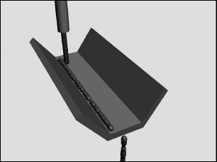
Tutorial: Making water flow down a trough
That should be enough destruction for a while. In this final example, you—ll make some water particles flow down a trough. You accomplish this using the Path Follow Space Warp.
To make water flow down a trough, follow these steps:
- Open the Water flowing down a trough.max file from the Chap 42 directory on the CD.
This file includes a simple trough made from primitives and a spline path that the water will follow.
- Select Particle Systems from the subcategory drop-down list, and click the Super Spray button. Create a Super Spray object in the Front viewport and position its pointer where you want the particles to first appear. In the Viewport Display section, select the Ticks particles option. In the Particle Generation rollout, set the Speed to 10 and the Variation to 100. Then set the Emit Start to 0 and the Display Until and Life values to 100. In the Particle Type rollout, select MetaParticles and enable the Automatic Coarseness option.
- Select the Space Warps category button, and choose Forces from the subcategory drop-down list. Click the Path Follow button, and create a Path Follow object; then click the Bind to Space Warp button on the main toolbar, and drag from the Path Follow icon to the first Super Spray icon. Open the Modify panel, select the Path Follow icon, click the Pick Shape Object button, and select the path in the viewports. Set the Start Frame to 0 and the Travel Time to 100.
Figure 42.20 shows the rendered result.
FIGURE 42.20 Water flowing down a trough using the Path Follow Space Warp
Summary
Space Warps are useful for adding forces and effects to objects in the scene. Max has several different types of Space Warps, and most of them can be applied only to certain object types. In this chapter, you learned the following:
- How to create Space Warps
- How to bind Space Warps to objects
- How to use all the various Space Warps in several subcategories
- How to combine Space Warps with particle systems to shatter glass and explode a planet
You can have Max dynamically compute all the animation frames in a scene using the physics-based MassFX engine, which is covered in the next chapter.