
CHAPTER 35
Using Animation Layers, Modifiers, and Complex Controllers
Using animation layers
Saving and loading animation files
Using the Point Cache modifier
Using the Morpher modifier
Adding secondary animation with the Flex modifier
Animating geometry deformations
Using other animation modifiers
Examining controllers
Just as layers can be used to organize a scene by placing unique objects on different layers, you also can separate the various animation motions into different layers. This gives you great control over how motions are organized and blended together.
If you've worked to animate some Max object and are pleased with the result, you can save the animation clip and reuse it. Several animation clips can be mixed together to create an entirely new animation sequence.
Modifiers can be used to deform and otherwise alter the geometry of objects, but they also can be used to affect other aspects of an object, including animated changes. One such important animation modifier is the Point Cache modifier. This modifier lets the movement of each vertex in the scene be saved to a cached file for immediate recall and for animating multiple objects simultaneously.
The Modifiers menu also includes an Animation submenu that contains many such modifiers. These modifiers are unique in that each of them changes with time. They can be useful as an alternate to controllers, but their resulting effects are very specific. Included with this submenu are modifiers such as Morpher, which allows an object to move through several different preset shapes, and Flex, which is used to add soft-body dynamics to your scene. Other animation modifiers include Melt and PathDeform.
This chapter also discusses all those miscellaneous Controllers that weren't covered earlier. These Controllers are more complex and enable a wide range of unique motions.
Using the Animation Layers Toolbar
Behind the scenes, animation layers add several new controller tracks to objects that are visible in the Motion panel and in the Track View interface, but the front end is accessible through a simple toolbar. The Animation Layers toolbar, shown in Figure 35.1, is similar in many ways to the Layers toolbar.
The Layers toolbar is covered in Chapter 6, “Selecting Objects and Setting Object Properties.”
FIGURE 35.1 The Animation Layers toolbar includes icons for defining and merging layers.
![]()
You can open the Animation Layers toolbar by right-clicking the main toolbar away from the buttons and selecting Animation Layers from the pop-up menu. Each of the toolbar buttons is labeled and explained in Table 35.1.
TABLE 35.1 Animation Layers Toolbar Controls
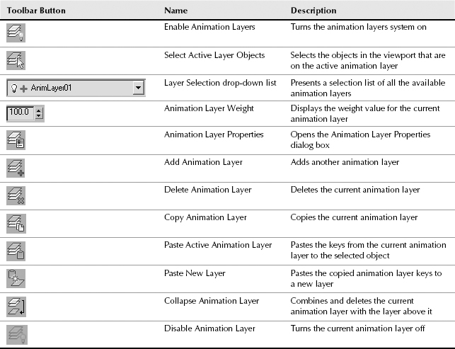
When a new animation layer is created using the Add Animation Layer button, a new entry is added to the Animation Layer Selection List. This list displays the default name of the animation layer as AnimLayer with a number. The original layer is named Base Layer. To the left of the animation layer name is a small light bulb icon that indicates whether the animation layer is enabled or disabled.
Caution
You cannot rename animation layer names.
Each layer can have a weight assigned to it. These weight values control how much influence the current animation layer has. The weight value also can be animated. For example, if a car is animated moving forward 100 meters over 50 frames, then weighting the animation layer to 30 causes the car to move forward only 30 meters over the 50 frames.
Working with Animation Layers
Animation layers are good for organizing motions into sets that can be easily turned on and off, but you also can use them to blend between motions to create an entirely new set of motions.
Note
Animations can be divided into primary motions, which are the major motions, and secondary motions, which are derivative motions that depend on the animation of other parts. Using animation layers, you can separate primary motions, like foot placement, from secondary motions, like a swinging arm, and adjust them independently.
Enabling animation layers
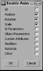
The first button on the Animation Layers toolbar is the Enable Animation Layers button. Clicking this button opens a dialog box, shown in Figure 35.2, where you can filter the type of keys to include in the animation layer.
FIGURE 35.2 The Enable Animation Layers dialog box lets you limit which type of keys are included.
The base animation layer can be disabled using the Disable Animation Layer button. This button is available only when you collapse all its layers. This changes the light bulb icon on the Selection list to indicate that the layer is disabled.
If Animation Layers are enabled for an object whose animation is loaded into the Motion Mixer, then a dialog box automatically appears, asking if you want to create a new map file for the animation.
Setting animation layers properties
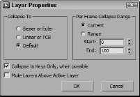
The button to the right of the Weight value opens the Layer Properties dialog box, shown in Figure 35.3. This dialog box lets you specify the type of controller to which the layers are collapsed. The options include Bézier (for Position and Scale tracks) or Euler (for Rotation tracks), Linear or TCB, and Default. You also can specify a range to collapse.
FIGURE 35.3 The Layer Properties dialog box lets you set the controller type to collapse to.
Collapsing animation layers
By collapsing layers, you combine the animation keys on each layer into a single set of keys that includes all the various motions. Be careful when collapsing; the results can be unexpected. Collapsing animation layers is accomplished with the Collapse Animation Layers button.
Tutorial: Using animation layers for a plane takeoff
Have you ever been to a small airport and watched the commuter planes take off? Sometimes they leave the ground and then return to the ground and then finally take off. It's like they need to get a good bounce to overcome gravity. This is a good example of when animation layers come in handy.
To animate a jet's takeoff using animation layers, follow these steps:
- Open the Mig take-off.max file from the Chap 35 directory on the CD.
This file includes a detailed Mig-29 jet model created by Viewpoint Datalabs.
- With the jet selected, open the Animation Layers toolbar by right-clicking the main toolbar away from the buttons and choosing Animation Layers from the pop-up menu.
- Click the Enable Animation Layers button, and enable the Position track, then click Ok to close the pop-up dialog box. This adds a Base Layer to the Selection list.
- Click the Auto Key, drag the Time Slider to frame 100, and move the jet to the far end of the runway. Then disable the Auto Key button. Set the Weight value for this layer to 0.
- In the Animation Layer toolbar, click the Add Animation Layer button to add a new layer. In the Create New Animation Layer dialog box that appears, select the Duplicate the Active Controller Type option and click OK. A new layer labeled AnimLayer01 is added to the Selection list.
- Click the Auto Key button again, drag the Time Slider to frame 100, and move the jet upward away from the runway. Then disable the Auto Key button again.
- Select the Base Layer from the Selection list in the Animation Layers toolbar and set its Weight value to 100. Then drag the Time Slider, and notice that the jet moves up at an angle over the 100 frames.
- Click the Auto Key button again, drag the Time Slider to frame 0, and set the Weight value for AnimLayer01 to 0; drag the Time Slider to frame 30, and set the Weight to 60; drag the Time Slider to frame 50, and set the Weight back to 0; and finally drag the Time Slider to frame 80, and set the Weight to 80. Then disable the Auto Key button again.
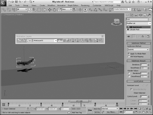
Dragging the Time Slider shows the jet bounce down the runway before taking off, as shown in Figure 35.4.
FIGURE 35.4 The Animation Layers feature provides a single parameter for controlling the plane's height.
Saving Animation Files
Before an animation sequence can be mixed in the Motion Mixer, it must be saved. The Motion Mixer easily can load any existing animation sequence in the current opened Max file, but saving a sequence to the local hard disk makes it accessible for other Max scenes. The Motion Mixer can be accessed using the Graph Editors ![]() Motion Mixer menu command. More on the Motion Mixer is presented as a bonus chapter on the book's CD.
Motion Mixer menu command. More on the Motion Mixer is presented as a bonus chapter on the book's CD.
Saving general animations
The animation of objects can be saved using the XML Animation File (XAF) format. To save the animation for the selected object, open the Save XML Animation File dialog box, shown in Figure 35.5, using the Animation ![]() Save Animation.
Save Animation.
FIGURE 35.5 The Save XML Animation File dialog box is used to save animations of the selected object.
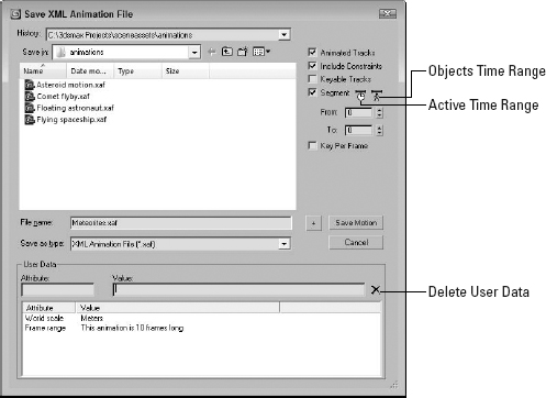
For general animations, you can select to include tracks, constraints, only keyable tracks, and a specific range. The User Data fields let you enter notes or specific data used by plug-ins about the animation sequence.
Loading Animation Sequences
The Load XML Animation File dialog box, shown in Figure 35.6, is opened using the Animation ![]() Load Animation menu command. It looks like a normal file dialog box, but it has some additional features.
Load Animation menu command. It looks like a normal file dialog box, but it has some additional features.
Caution
Within the Character Assembly rollout for Character objects is a button to Save Animation. This button saves character animations using the ANM file format, which cannot be opened using the Animation ![]() Load Animation menu command.
Load Animation menu command.
The Relative and Absolute options determine whether the animation is loaded relative to the object's current location or whether it is loaded into the frames where it was saved. The Replace and Insert options let the new keys overwrite the existing ones or move them out to insert the loaded keys. You can even select the frame where the new keys are loaded. The Load Motion button lets you load an existing mapping file named the same as the animation file if one exists or lets you create a new one.
Note
The Animation ![]() Load Animation and Animation
Load Animation and Animation ![]() Save Animation menu commands are active only when an object is selected.
Save Animation menu commands are active only when an object is selected.
FIGURE 35.6 The Load XML Animation File dialog box lets you load animation files from one scene and apply them to another.
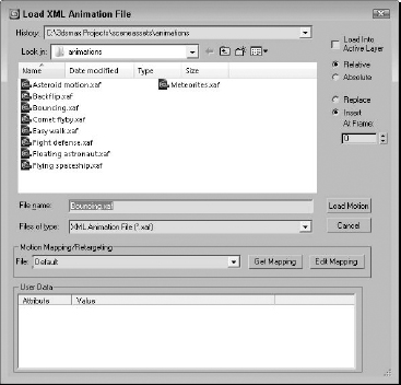
Mapping files are listed in the drop-down list for easy selection, or you can use the Get Mapping button to select a different mapping file to load. Mapping files are saved with the .xmm file extension. The Edit Mapping button is active when a mapping associated with the file in the Load Animation dialog box opens the Map Animation dialog box, where you can define the mapping between objects in the two scenes.
Mapping animated objects
Mapping files define a relationship between objects in the saved animation file and objects in the current Max file. These relationships allow the animation keys to be transferred from one scene object to another.
Using the Map Animation dialog box
The Map Animation dialog box, shown in Figure 35.7, includes several rollouts. The Motion Mapping Parameters rollout includes options for allowing Max to make its best guess at mapping objects. If the scenes are fairly similar, then this option may be just the ticket. The Exact Names, Closest Names, and Hierarchy buttons allow Max to attempt the mapping on its own. This works especially well on bipeds that use the default naming conventions. You also can select to have Max look at the various controllers that are used when trying to match up objects.
FIGURE 35.7 The Map Animation dialog box lets you map objects to receive animation.
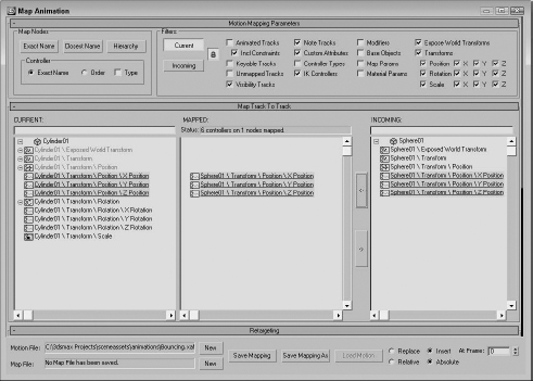
The Filters section lets you filter out the tracks that you don't want to see. The Lock button applies the selected filters to both the Current and Incoming lists.
The Map Track to Track rollout consists of three lists. The left list contains all the tracks for the current scene objects, the middle list contains all the mapped tracks, and the right list contains all the tracks from the incoming animation file. Select tracks and click the button with the left-pointing arrow to add tracks to the Mapped list; click the other arrow button to remove them.
At the bottom of the Map Animation dialog box are buttons for saving the current mapping file.
Retargeting animations
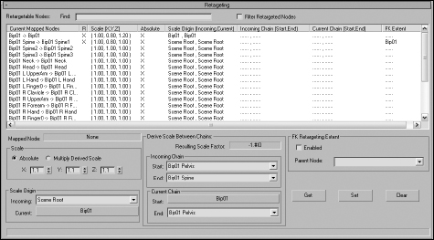
The Retargeting rollout, shown in Figure 35.8, lets you specify how the scale changes between certain mapped objects. Scale values can be entered for the mapped nodes as Absolute or Derived Scale values for each axis. Derived scale values can be obtained from a specific origin object. After the settings are right, the Set button applies the scaling to the selected mapping.
FIGURE 35.8 Use the Retargeting rollout to specify how the scale changes between mapped objects.
Baking Animation Keys with the Point Cache Modifier
When you add keys to an object to control its animation using modifiers, the modifiers remain with the object and can be revisited and altered as needed. However, if you have multiple objects that follow the same set of keys, such as for a crowd scene, then including a set of modifiers for each object can increase the overhead many times over. A simple solution is to bake all the keys into the object, allowing all the keys to be pulled from an external file. This frees the resources required to animate multiple objects and makes the animated keys portable. The Point Cache modifier makes this possible.
You also can use the Point Cache modifier when playback in the viewport is too slow because Max needs to compute the vertex positions of a huge number of vertices. Reading their position from a separate file increases the playback speed. You also can use the file on a cloned object to control its motion at a different speed.
The Point Cache modifier records the movement of every vertex of an object to a file. Point Cache files have the .xml extension, but they can also be saved using the older .pc2 extension. To create a Point Cache file, click the New button and name a new file on the hard drive. Then set the range of the animation to capture and click the Record button. Once recorded, the total number of points along with the sample rate and range are displayed for the active cache.
Caution
Point Cache files can be loaded and used only on objects with the same number of vertices as the original used to record the file.
If you select the Disable Modifiers Below option, then all modifiers below the Point Cache in the Modifier Stack are disabled. You can enable the Relative Offset option and set the Strength value to cause the cached animation to be exaggerated or even reversed. In the Playback Type section, you can control the range of the animation.
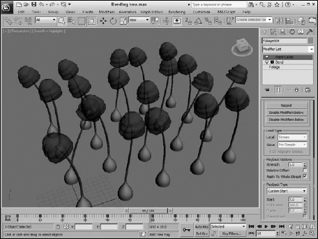
Tutorial: Trees in a hurricane
As an example of using the Point Cache modifier, you'll use a tree that is bending under violent forces such as a hurricane and duplicate it many times.
To create a forest of trees in a hurricane, follow these steps:
- Open the Bending tree.max file from the Chap 35 directory on the CD.
This file includes an animated tree swaying back and forth using the Bend modifier.
- Select the tree and choose the Modifiers
 Cache Tools Point Cache menu to apply the Point Cache modifier to the tree.
 - In the Parameters rollout, click the New button, create a file named “Bending tree.xml,” and click the Save button to create the animation file. Then click the Record button to save all the animation data to the file.
- Select the tree and delete its Bend modifier. Then use the Tools Array dialog box to create several rows of trees. Be sure to create the trees as copies and not instances.
- Select several random trees and change the Playback Type to Custom Start in the Parameters rollout and change the Start Frame to −2 to cause some random motion.
- Press the Play Animation button to see the results.
Figure 35.9 shows several of the trees being moved about by the storm.
FIGURE 35.9 Using the Point Cache modifier, you can animate a whole forest of trees.
Using the Animation Modifiers
Animation is more than just moving an object from here to there. All objects move not only with major transformations but with lots of secondary motions also. When a human character walks, the motions of his arms and legs are major, but the secondary motions of his swinging hips and bobbing shoulders make the walk realistic. Many of the animation modifiers enable these key secondary motions.
All the animation modifiers presented in this chapter are located in the Modifiers ![]() Animation submenu.
Animation submenu.
Cross-Reference
Also included among the Animation modifiers are several Skin modifiers, which are used to make an object move by attaching it to an underlying skeleton. The Skin modifiers are covered in Chapter 40, “Skinning Characters.”
Morpher modifier
The Morpher modifier lets you change a shape from one form into another. You can apply this modifier only to objects with the same number of vertices.
Cross-Reference
In many ways, the Morpher modifier is similar to the Morph compound object, which is covered in Chapter 27, “Working with Compound Objects.”
The Morpher modifier can be very useful for creating facial expressions and character lip-synching. You can also use it to morph materials. Max makes 100 separate channels available for morph targets, and channels can be mixed. You can use the Morpher modifier in conjunction with the Morph material. For example, you could use the Morph material to blush a character for an embarrassed expression.
Tip
When it comes to making facial expressions, a mirror and your own face can be the biggest help. Coworkers may look at you funny, but your facial expressions will benefit from the exercise.
The first task before using this modifier is to create all the different morph targets. Because the morph targets need to contain the same number of vertices as the base object, make a copy of the base object for each morph target that you are going to create. As you create these targets, be careful not to add or delete any vertices from the object.
Note
Because morph targets deal with each vertex independently, you cannot mirror morph targets, so if you want a morph target for raising the left eyebrow and a morph target for raising the right eyebrow, you need to create each morph target by hand.
After all your morph targets are created, select a channel in the Channel Parameters rollout, shown in Figure 35.10, and use the Pick Object from Scene button to select the morph target for that channel. Another option for picking is to use Capture Current State. After a morph target has been added to a channel, you can view it in the Channel List rollout.
FIGURE 35.10 The Morpher modifier's rollouts
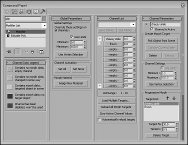
As you animate, you can specify the amount of each morph target to include in the frame using the value to the right of the channel name in the Channel List rollout. The slim color bar to the left of the channel name designates the status of the channel. You can find information on what each color represents in the Channel Color Legend rollout.
The Channel Parameters rollout also includes a Progressive Morph section. This feature lets you define an intermediate step for how the morph is to progress, with the final step being the morph target. Using these intermediate steps, you can control how the object morphs.
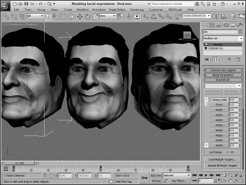
Tutorial: Morphing facial expressions
The Morpher modifier is very helpful when you're trying to morph facial expressions, such as those to make a character talk. With the various sounds added to the different channels, you can quickly morph between them. In this example, you use the Morpher modifier to change the facial expressions of the general character.
Tip
When creating facial expressions, be sure to enable the Soft Selection features, which make modifying the face meshes much easier.
To change facial expressions using the Morpher modifier, follow these steps:
- Open the Morphing facial expressions.max file from the Chap 35 directory on the CD.
This file includes a head model created by Viewpoint Datalabs. The model has been copied twice, and the morph targets have already been created by modifying the subobjects around the mouth.
- Select the face on the left, and select the Modifiers Animation Modifiers Morpher menu command to apply the Morpher modifier.
- In the Channel List rollout, select channel 1, click the Pick Object from Scene button, and select the middle face object. Then select the second empty channel from the Channel List rollout; in the Channel Parameters rollout, again click the Pick Object from Scene button and select the face on the right.
If you look in the Channel List rollout, you'll see “cheesy smile” in Channel 1 and “frown” in Channel 2.
- Click the Auto Key button (or press the N key), drag the Time Slider to frame 50, and then increase the “cheesy smile” channel in the Channel List rollout to 50. Drag the Time Slider to frame 100, and increase the “frown” channel to 100 and the “cheesy smile” channel to 0. Then return the Time Slider to 50, and set the “frown” channel to 0.
- Click the Play Animation button in the Time Controls to see the resulting animation.
Figure 35.11 shows the three facial expressions. The Morpher modifier is applied to the left face.
Tip
Be sure to keep the morph target objects around. You can hide them in the scene or select them and save them to a separate file with the File ![]() Save Selected menu command.
Save Selected menu command.
FIGURE 35.11 Using the Morpher modifier, you can morph one facial expression into another.
Using the Flex modifier
The Flex modifier can add soft body dynamic characteristics to an object. The characteristic of a soft body is one that moves freely under a force. Examples of soft body objects are clothes, hair, and balloons. The opposite of soft body dynamics is rigid body dynamics. Think of a statue in the park. When the wind blows, it doesn't move. The statue is an example of a rigid body. On the other hand, the flag flying over the library moves all over when the wind blows. The flag is an example of a soft body.
Cross-Reference
Soft body objects can also be defined and simulated using reactor, which is covered in Chapter 43, “Simulating Physics-Based Motion with MassFX.”
Another way to think of soft bodies is to think of things that can flex. Objects such as a clothesline flex under very little stress, but other objects like a CD flex only a little when you apply a significant force. The settings of the Flex modifier make it possible to represent all kinds of soft body objects.
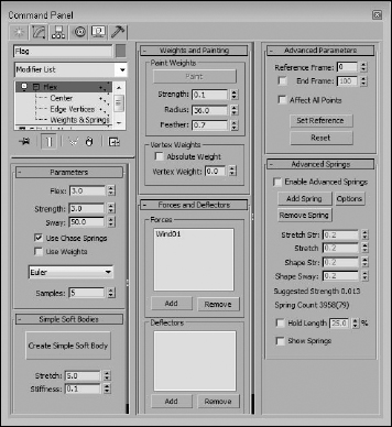
Figure 35.12 shows many of the rollouts available for the Flex modifier.
FIGURE 35.12 The Flex modifier rollout lets you control the flex settings.
Flex subobjects
In the Modifier Stack, the Flex modifier has three subobjects that you can access: Center, Edge Vertices, and Weights and Springs. The Center subobject is a simple box gizmo that marks the center of the flex effect. Portions of the object that are farther from the center move a greater distance. The Edge Vertices subobject can be selected to control the direction and falloff of the flex effect. The Weights and Springs rollout controls the Weights and Springs subobject.
Setting flex strength
The Parameters rollout includes a Flex value, which controls the amount of bending the object does; a Strength value, which controls the rigidity of the object; and a Sway value, which controls how long the flexing object moves back and forth before coming to a stop. An antenna on a car is an example of an object that has fairly high Flex and Sway values and a low Strength value.
Chase Springs cause an object to return to its original position when the force is removed. A twig on a tree is an example of an object with Chase Springs. The Use Chase Springs option lets you disable these springs. A piece of cloth is an example of when you would want Chase Springs disabled.
Selecting the Weights and Springs subobject lets you apply weights to certain selected springs. You can disable these weights using the Use Weights option. If you disable these weights, the entire object acts together.
The Flex modifier offers three solution methods to compute the motions of objects. These are presented in a drop-down list. The Euler solution is the simplest method, but it typically requires five samples to complete an accurate solution. The Midpoint and Runge-Kutta4 solutions are more accurate and require fewer samples, but they require more computational time. Setting the Samples value higher produces a more accurate solution.
Creating simple soft bodies
In the Simple Soft Bodies rollout, use the Create Simple Soft Body button to automatically set the springs for the selected object to act like a soft body. You can also set the amount of Stretch and Stiffness the object has. For cloth, you want to use a high Stretch value and a low Stiffness value, but a racquetball would have both high Stretch and Stiffness values.
Tip
You can manually set the spring settings for the object using the Advanced Springs rollout.
Painting weights
When you select the Weights and Springs subobject mode, the spring vertices are displayed on the object. The vertices are colored to reflect their weight. By default, the vertices that are farthest from the object's pivot point have the lowest weight value. Vertices with the greatest weight value (closest to 1) are colored red, and spring vertices with the lowest weight value (closest to −1) are blue. Vertices in between these two values are orange and yellow. The lower-weighted vertices move the greatest distance, and the higher-weighted vertices move the least.
Selecting the Weights and Springs subobject also enables the Paint button in the Weights and Springs rollout. Clicking this button puts you in Paint mode, where you can change the weight of the spring vertices by dragging a paint gizmo over the top of the object in the viewports. As you paint the spring vertices, they change color to reflect their new weights.
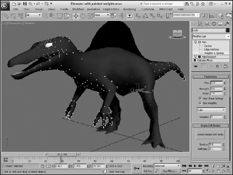
The Strength value sets the amount of weight applied to the vertices. This value can be negative. The Radius and Feather settings change the size and softness of the Paint brush. Figure 35.13 shows a dinosaur model with the Flex modifier applied. The dinosaur has had some weights painted so its tail, arms, and neck move under the influence of the Flex modifier. The blue vertices are the weights that don't move as much.
FIGURE 35.13 Use the Paint button to change the weight of the spring vertices.
The weights applied using the Paint button are relative to the existing vertex weight. If you select the Absolute Weight option, then the Vertex Weight value is applied to the selected vertices.
Adding Forces and Deflectors
To see the effect of the Flex modifier, you need to add some motion to the scene. The flex object flexes only when it is moving. One of the easiest ways to add motion to the scene is with Space Warps.
The Forces and Deflectors rollout includes two lists: one for Forces and one for Deflectors. Below each are Add and Remove buttons. Using these buttons, you can add and remove Space Warps from the list. The Forces list can use any of the Space Warps in the Forces subcategory (except for Path Follow). The Deflector list can include any of the Space Warps in the Defectors subcategory.
Tip
When you add Space Warps to the Forces and Deflectors list for the Flex modifier, they do not need to be bound to the object.
Manually creating springs
The final two rollouts for the Flex modifier are Advanced Parameters and Advanced Springs. The Advanced Parameters rollout includes settings for controlling the Start and End frames where the Flex modifier has an effect. The Affect All Points option ignores any subobject selections and applies the modifier to the entire object. The Set Reference button updates all viewports, and the Reset button resets all the vertices’ weights to their default values.
You can use the Advanced Springs rollout to manually add and configure springs to the object. Clicking the Options button opens a dialog box where you can select the type of spring to add to the selected vertices, including Edge and Shape springs. Edge springs are applied to vertices at the edges of an object, and Shape springs are applied between vertices. For these advanced springs, you can set the Stretch Strength, Stretch Sway, Shape Strength, and Shape Sway.
Melt modifier
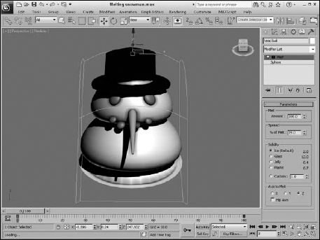
The Melt modifier simulates an object melting by sagging and spreading edges over time. Melt parameters include Amount and Spread values, Solidity (which can be Ice, Glass, Jelly, or Plastic), and a Melt Axis.
Figure 35.14 shows the Melt modifier applied to the snowman model (it was inevitable).
FIGURE 35.14 The Melt modifier slowly deforms objects to a flat plane.
PatchDeform and SurfDeform modifiers
Among the animation modifiers are several that are similar in function but that work on different types of objects. The PatchDeform modifier uses patches, and the SurfDeform modifier deforms an object according to a NURBS surface.
In the Parameters rollout for each of these modifiers is a Pick Patch (or Surface) button that lets you select an object to use in the deformation process. After the object is selected, you can enter the Percent and Stretch values for the U and V directions, along with a Rotation value.
Note
The PatchDeform modifier is also available as a World Space Modifier (WSM). WSMs are similar to the normal Object Space Modifiers (OSM), except that they use World Space coordinates instead of Object Space coordinates. The most noticeable differences are that WSMs don't use gizmos and that the OSM moves the patch to the object, while the WSM causes the object to move to the patch.
Tutorial: Deforming a car going over a hill
Have you seen those commercials that use rubber cars to follow the curvature of the road as they drive? In this tutorial, you use the PatchDeform modifier to bend a car over a hill made from a patch.
To deform a car according to a patch surface, follow these steps:
- Open the Car bending over a hill.max file from the Chap 35 directory on the CD.
This file contains a simple hill made from patch objects and a car model created by Viewpoint Datalabs.
- Select the car model, and choose Modifiers Animation Modifiers PatchDeform (WSM). Then click the Pick Patch button in the Parameters rollout, and select the hill object.
This applies the World Space PatchDeform modifier (WSM) to the car object and moves the car to align with the hill.
- Set the V Percent value to 0 in the Parameters rollout. Then, click the Auto Key button (or press the N key) to enable key mode, and drag the Time Slider to frame 100. Then set the V Percent value to −50, and click the Auto Key button again to disable key mode.
- Click the Play button (or press the / key) to see the car deform over the hill.
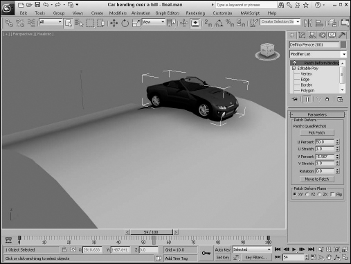
Figure 35.15 shows the results of this tutorial.
FIGURE 35.15 The car model hugs the road, thanks to the PatchDeform modifier.
PathDeform modifier
The PathDeform modifier uses a spline path to deform an object. The Pick Path button lets you select a spline to use in the deformation process. You can select either an open or closed spline. The Parameters rollout also includes spinners for controlling the Percent, Stretch, Rotation, and Twist of the object. The Percent value is the distance the object moves along the path.
Note
If you use the PathDeform modifier, you can benefit from using the Follow/Bank utility, which gives you control over how the object follows and banks along the path.
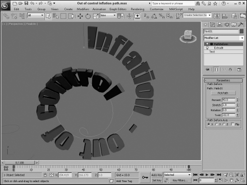
Figure 35.16 shows some text wrapped around a spline path.
FIGURE 35.16 The text in this example has been deformed around a spline path using the PathDeform modifier.
Linked XForm modifier
The Linked XForm modifier passes all transformations of one object onto another, but not vice versa. The object that controls the transformation is designated as the Control Object and is selected via the Pick Control Object button (which is the only control in the Parameters rollout for this modifier). After the Control object is selected, the Control Object controls the selected object's transforms, but the object that is being controlled can move independently of the control object without affecting the control object.
SplineIK Control modifier
The SplineIK Control modifier can be applied only to spline objects. In the Spline IK Control Parameters rollout, you can click the Create Helpers button, which adds a dummy object to every vertex on the spline. These dummy objects make it much easier to control the spline without having to enter vertex subobject mode. You can also specify how the dummy objects are linked and how they are displayed.
Attribute Holder modifier
The Attribute Holder modifier displays all custom defined attributes in their own rollout. Creating custom attributes and wiring attributes is discussed in Chapter 36, “Animating with the Expression Controller and Wiring Parameters.”
Examining Complex Controllers
Now that you are somewhat familiar with controllers and how they work, let's look at some more complex controllers. Max includes a vast assortment of controllers, and you can add more controllers as plug-ins.
Transform controllers
Multi-track transform controllers work with the Position, Rotation, and Scale tracks all at the same time. You access them by selecting the Transform track in the Motion panel and then clicking the Assign Controller button or by choosing the Animation ![]() Transform Controllers menu command.
Transform Controllers menu command.
Note
Each of the available constraints is listed again in the appropriate controller submenu.
Position/Rotation/Scale Transform controller
![]() The Position/Rotation/Scale Transform controller is the default controller for all transforms. This controller includes a Bézier controller for the Position and Scale tracks and a Euler XYZ controller for the Rotation track.
The Position/Rotation/Scale Transform controller is the default controller for all transforms. This controller includes a Bézier controller for the Position and Scale tracks and a Euler XYZ controller for the Rotation track.
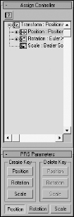
The PRS Parameters rollout, shown in Figure 35.17, lets you create and delete keys for Position, Rotation, and Scale transforms. The Position, Rotation, and Scale buttons control the fields that appear in the Key Info rollouts positioned below the PRS Parameters rollout.
Script controller
![]() The Script controller is similar to the Expression controller, except that it can work with the MAXScript lines of code for controlling the scene. Right-clicking a track with the Script controller assigned and selecting Properties opens the Script Controller dialog box. Script controllers are available for all transform tracks including Transform, Position, Rotation, and Scale. The flexibility of the Script controller is quite robust. The Script controller is covered in more detail at the end of this chapter, as is the Expression controller.
The Script controller is similar to the Expression controller, except that it can work with the MAXScript lines of code for controlling the scene. Right-clicking a track with the Script controller assigned and selecting Properties opens the Script Controller dialog box. Script controllers are available for all transform tracks including Transform, Position, Rotation, and Scale. The flexibility of the Script controller is quite robust. The Script controller is covered in more detail at the end of this chapter, as is the Expression controller.
FIGURE 35.17 The PRS Parameters rollout is the default transform controller.
On the CD-ROM
For more information on MAXScript, Bonus Chapter 21, “Automating with MAXScript,” on the CD.
XRef controller
If you have a defined motion used by an object in another file that you want to access, you can use the XRef controller. This controller can be assigned only to the Transform track. When this controller is assigned, a file dialog box opens where you can select the XRef file; then in the Merge Object dialog box, you can select a specific object that has the controller and motion you want to use.
![]() In the Parameters rollout for the XRef controller is a button to open the XRef Object dialog box with the XRef Record highlighted. The Parameters rollout also lists the XRef file, object, and status.
In the Parameters rollout for the XRef controller is a button to open the XRef Object dialog box with the XRef Record highlighted. The Parameters rollout also lists the XRef file, object, and status.
Cross-Reference
XRefs are covered in detail in Chapter 3, “Working with Files, Importing, and Exporting.”
Position track controllers
Position track controller types include some of the common default controllers and can be assigned to the Position track. They typically work with three unique values representing the X-, Y-, and Z-axes. These controllers can be assigned from the Animation ![]() Position Controllers menu. Many of the controllers found in this menu also are found in the Rotation and Scale Controllers menu.
Position Controllers menu. Many of the controllers found in this menu also are found in the Rotation and Scale Controllers menu.
Audio controller
![]() The Audio controller can control an object's transform, color, or parameter value in response to the amplitude of a sound file. The Audio Controller dialog box, shown in Figure 35.18, includes Choose Sound and Remove Sound buttons for loading or removing sound files. You can access the Audio Controller dialog box by right-clicking on the track where the Audio Controller is assigned and selecting the Properties menu from the pop-up menu, or simply double-click on the track.
The Audio controller can control an object's transform, color, or parameter value in response to the amplitude of a sound file. The Audio Controller dialog box, shown in Figure 35.18, includes Choose Sound and Remove Sound buttons for loading or removing sound files. You can access the Audio Controller dialog box by right-clicking on the track where the Audio Controller is assigned and selecting the Properties menu from the pop-up menu, or simply double-click on the track.
FIGURE 35.18 The Audio Controller dialog box lets you change values based on the amplitude of a sound file.
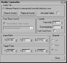
The Real Time Control drop-down list lets you specify a device to control the system. To control the sound input, you can specify a Sample Threshold and Oversampling rate. You also can set Base Point and Target Point values for each axis. The Channel options let you specify which channel to use: Left, Right, or Mix.
Motion Clip Slave controller
The Motion Clip Slave controller lets a linked motion clip that is loaded and defined in the Motion Mixer control the object's transform.
Motion Capture controller
![]() The Motion Capture controller allows you to control an object's transforms using an external device such as a mouse, keyboard, joystick, or MIDI device. This controller works with the Motion Capture utility to capture motion data.
The Motion Capture controller allows you to control an object's transforms using an external device such as a mouse, keyboard, joystick, or MIDI device. This controller works with the Motion Capture utility to capture motion data.
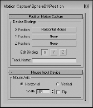
After you assign the Motion Capture controller to a track, right-click the track and select Properties from the pop-up menu to open the Motion Capture panel, shown in Figure 35.19. This dialog box lets you select the devices to use to control the motion of the track values. Options include Keyboard, Mouse, Joystick, and MIDI devices.
FIGURE 35.19 The Motion Capture controller lets you control track values using external devices.
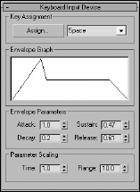
For the Keyboard control, the Keyboard Input Device rollout appears, as shown in Figure 35.20. The Assign button lets you select a keyboard key to track. The other settings control the Envelope Graph, which defines how quickly key presses are tracked.
FIGURE 35.20 The Keyboard Input Device rollout lets you select which key press is captured.
The Motion Capture dialog box defines only which device controls which values. The actual capturing of data is accomplished using the Motion Capture utility. Selecting the Motion Capture utility in the Utility panel displays the Motion Capture rollout. This rollout includes buttons to Start, Stop, and Test the data-capturing process.
Before you can use the Start, Stop, and Test buttons, you need to select the tracks to capture from the Tracks list. The Record Range section lets you set the Preroll, In, and Out values, which are the frame numbers to include. You also can set the number of Samples Per Frame. The Reduce Keys option removes any unnecessary keys, if enabled.
Tutorial: Drawing with a pencil with the Motion Capture controller
Some motions, such as drawing with a pencil, are natural motions for our hands, but they become very difficult when you're trying to animate using keyframes. This tutorial uses the Motion Capture controller and utility to animate the natural motion of drawing with a pencil.
To animate a pencil drawing on paper, follow these steps:
- Open the Drawing with a pencil.max file from the Chap 35 directory on the CD.
This file has a pencil object positioned on a piece of paper.
- Select the pencil object, open the Motion panel, and select the Position track for the pencil object. Then click the Assign Controller button, and double-click the Position Motion Capture selection.
The Motion Capture dialog box opens.
- Click the X Position button, and double-click the Mouse Input Device selection. Then click the Y Position button, and double-click the Mouse Input Device selection again. In the Mouse Input Device rollout, select the Vertical option. This sets the X Position to the Horizontal Mouse movement and the Y Position to the Vertical Mouse movement. Close the Motion Capture dialog box.
- Open the Utilities panel, and click the Motion Capture button. In the Motion Capture rollout, select the Position track, and get the mouse ready to move. Then click the Start button in the Record Controls section, and move the mouse as if you were drawing with the mouse. The pencil object moves in the viewport along with your mouse movements.
The Motion Capture utility creates a key for each frame. It quits capturing the motion when it reaches frame 100.
- Click the Play Animation button (or press the / key) to see the results.
Figure 35.21 shows the scene after the Motion Capture controller has computed all the frames.
Quaternion (TCB) controller
![]() The Quaternion (TCB) controller produces curved animation paths similar to the Bézier controller, but it uses the values for Tension, Continuity, and Bias to define their curvature. The benefit of this controller is that it enables objects to be rotated without having the problem of Gimbal lock, which can happen when the Euler XYZ controller is used. Gimbal lock can occur when two of the rotation axes become aligned, causing the object to lose one of its degrees of freedom.
The Quaternion (TCB) controller produces curved animation paths similar to the Bézier controller, but it uses the values for Tension, Continuity, and Bias to define their curvature. The benefit of this controller is that it enables objects to be rotated without having the problem of Gimbal lock, which can happen when the Euler XYZ controller is used. Gimbal lock can occur when two of the rotation axes become aligned, causing the object to lose one of its degrees of freedom.
The parameters for this controller are displayed in a single Key Info rollout. Like the Bézier controller rollouts, the Quaternion (TCB) controller rollout includes arrows and Key, Time, and Value fields. It also includes a graph of the TCB values; the red plus sign represents the current key's position, while the rest of the graph shows the regular increments of time as black plus signs. Changing the Tension, Continuity, and Bias values in the fields below the graph changes its shape. Right-clicking the track and selecting Properties from the pop-up menu opens the TCB graph dialog box, shown in Figure 35.22.
FIGURE 35.21 The Motion Capture controller and utility let you animate with a mouse, keyboard, joystick, or MIDI device.
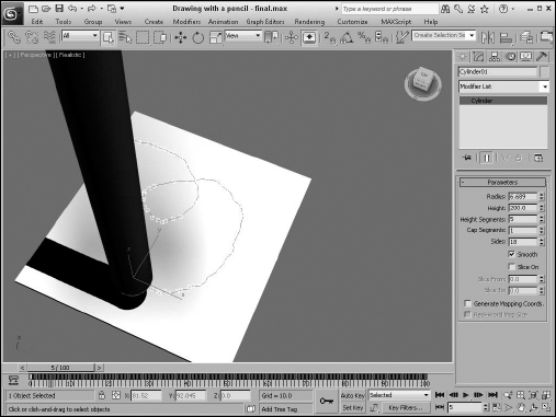
FIGURE 35.22 This dialog box shows, and lets you control, a curve defined by the Tension, Continuity, and Bias values.
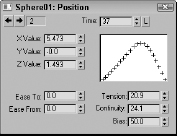
The Tension value controls the amount of curvature: High Tension values produce a straight line leading into and away from the key, and low Tension values produce a round curve. The Continuity value controls how continuous, or smooth, the curve is around the key: The default value of 25 produces the smoothest curves, whereas high and low Continuity values produce sharp peaks from the top or bottom. The Bias value controls how the curve comes into and leaves the key point, with high Bias values causing a bump to the right of the key and low Bias values causing a bump to the left.
The Ease To and Ease From values control how quickly the key is approached or left.
Enabling the trajectory path by clicking the Trajectory button in the Motion panel lets you see the changes to the path as they are made in the Key Info rollout.
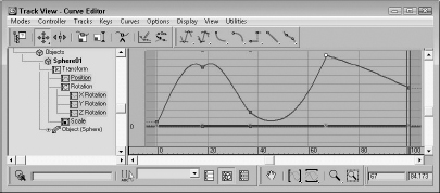
Figure 35.23 shows three TCB curves assigned to the Position track of an object.
Note
Some controllers are assigned through the Animation menu and others through the Assign Controller dialog box. Look to both if you cannot find a specific controller.
FIGURE 35.23 The TCB controller offers a different way to work with curves.
Reaction controller
![]() The Reaction controller changes its values as a reaction to another controller. This controller is different from the Attachment controller in that the motions don't need to be in the same direction. For example, you can have one object rise as another object moves to the side.
The Reaction controller changes its values as a reaction to another controller. This controller is different from the Attachment controller in that the motions don't need to be in the same direction. For example, you can have one object rise as another object moves to the side.
Cross-Reference
Don't confuse the Reaction controller with the reactor plug-in, which computes motion based on physical dynamics. The reactor plug-in is covered in Chapter 43, “Simulating Physics-Based Motion with MassFX.”
After the Reaction controller is assigned to a track, you can define the reactions using the Reaction Manager dialog box, shown in Figure 35.24. Selecting and right-clicking the track with this controller assigned and selecting Properties from the pop-up menu opens this dialog box. You also can open the Reaction Manager dialog box using the Animation ![]() Reaction Manager menu.
Reaction Manager menu.
The Reaction Manager is made up of two lists and a graph of function curves. The top list holds all the object values that are involved in reactions. These are listed in a hierarchy with the master object listed above the slave object. A single master object can control several slave parameters.
The buttons above the Reactions list let you add new masters, slaves, and selected objects to the list. The cursor changes after you click any of these buttons, allowing you to click an object in the viewport and select a value from a pop-up menu.
FIGURE 35.24 The Reaction Manager dialog box lets you set the parameters of a reaction.
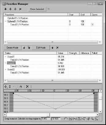
For the slave objects selected in the Reactions list, you can set states using the buttons above the States list. To set a state, click the Create Mode button, drag the Time Slider to the appropriate frame, and change the slave object's value. Then click the Create State button to create the target object state. Several unique states can be defined for each slave object.
State values can be changed by accessing the Edit Mode button or by editing the curves displayed at the bottom of the Reaction Manager dialog box.
Rotation and Scale track controllers
The Rotation and Scale track controller types include some of the common default controllers and can be assigned to the Rotation and Scale tracks. They typically work with three unique values representing the X-, Y-, and Z-axes. These controllers can be assigned from the Animation ![]() Rotation (Scale) Controllers menu. Many of the controllers found in this menu also are found in the Position Controllers menu. Only the controllers unique to the Rotation and Scale tracks are covered here.
Rotation (Scale) Controllers menu. Many of the controllers found in this menu also are found in the Position Controllers menu. Only the controllers unique to the Rotation and Scale tracks are covered here.
Euler XYZ Rotation controller
![]() The Euler XYZ Rotation controller lets you control the rotation angle along the X-, Y-, and Z-axes based on a single float value for each frame. Euler rotation is different from Max's default rotation method (which is quaternion rotation and not as smooth).
The Euler XYZ Rotation controller lets you control the rotation angle along the X-, Y-, and Z-axes based on a single float value for each frame. Euler rotation is different from Max's default rotation method (which is quaternion rotation and not as smooth).
The main difference is that Euler rotation gives you access to the function curves. Using these curves, you can smoothly define the rotation motion of the object.
Note
Euler XYZ Rotation values are in radians instead of degrees. If using these as part of an expression, be sure to use radians and not degrees. Radians are much smaller values than degrees. A full revolution is 360 degrees or 2 times Pi radians, so 1 degree equals about 0.0174 radians.
The Euler Parameters rollout lets you choose the Axis Order, which is the order in which the axes are calculated. You also can choose which axis to work with.
Caution
The Euler XYZ controller is susceptible to Gimbal lock, which occurs when two of the three axes align to each other, causing the object to lose a degree of freedom. This can be minimized by making the axis that rotates the least the middle axis. You also can use the Euler Filter utility in the Track View to avoid Gimbal lock, or you can use the Quaternion controller instead.
Smooth Rotation controller
![]() The Smooth Rotation controller automatically produces a smooth rotation. This controller doesn't add any new keys; it simply changes the timing of the existing keys to produce a smooth rotation. It does not have any parameters.
The Smooth Rotation controller automatically produces a smooth rotation. This controller doesn't add any new keys; it simply changes the timing of the existing keys to produce a smooth rotation. It does not have any parameters.
Parameter controllers
Other controllers are used to affect the animated changes of parameters whether they are float, Point3, or other parameter types. Many of these controllers combine several controllers into one, such as the List and Block controllers. Others include separate interfaces, such as the Waveform controller for defining the controller's functions.
Most of these special-purpose controllers can be assigned only by using the Track View window. The Motion panel contains only the tracks for transformations.
Boolean controller
![]() The Boolean controller, like the On/Off controller, can hold one of two states: 0 for off and 1 for on. But, unlike the On/Off controller, the Boolean controller changes only when a different state is encountered.
The Boolean controller, like the On/Off controller, can hold one of two states: 0 for off and 1 for on. But, unlike the On/Off controller, the Boolean controller changes only when a different state is encountered.
Limit controller
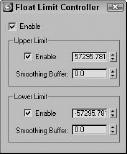
![]() The Limit controller sets limits for the motion or parameters of the selected controller. It is applied on top of the existing controller and opens the Limit Controller dialog box, shown in Figure 35.25, when applied.
The Limit controller sets limits for the motion or parameters of the selected controller. It is applied on top of the existing controller and opens the Limit Controller dialog box, shown in Figure 35.25, when applied.
The upper limit is the maximum value to which the controller can be set, and the lower limit is the minimum value that the controller uses. Controller values may exceed the upper and lower limit values, but the object's motion stops at the limit values when the Limit controller is enabled. The Smoothing Buffer value provides a range that gradually alters the value as it approaches the limit value.
FIGURE 35.25 The Limit controller dialog box lets you set upper and lower limits for the current controller value.
After a Limit controller is applied to an object, you can quickly change its upper and lower limit values by right-clicking the object in the Track View and accessing the Limit Controller option in the quadmenu.
Tip
You can disable all limits at once using the Animation ![]() Toggle Limits menu command.
Toggle Limits menu command.
List controller
![]() You can use the List controller to apply several controllers at once. This feature enables you to produce smaller, subtler deviations, such as adding some noise to a normal Path controller.
You can use the List controller to apply several controllers at once. This feature enables you to produce smaller, subtler deviations, such as adding some noise to a normal Path controller.
When the List controller is applied, the default track appears as a subtrack along with another subtrack labeled Available. By selecting the Available subtrack and clicking the Assign Controller button, you can assign additional controllers to the current track.
All subtrack controllers are included in the List rollout of the Motion panel. You also can access this list by right-clicking the track and selecting Properties from the pop-up menu. The order of the list is important because it defines which controllers are computed first.
The Set Active button lets you specify which controller you can interactively control in the viewport; the active controller is marked with an arrow, which is displayed to the left of the name. You also can cut and paste controllers from and to the list. Because you can use the same controller type multiple times, you can distinguish each one by entering a name in the Name field.
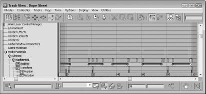
On/Off controller
![]() The On/Off controller works on tracks that hold a binary value, such as the Visibility track; you can use it to turn the track on and off or to enable and disable options. In the Track View, each On section is displayed in blue, with keys alternating between on and off. No parameters exist for this controller. Figure 35.26 shows a Visibility track that has been added to a sphere object. This track was added using the Tracks
The On/Off controller works on tracks that hold a binary value, such as the Visibility track; you can use it to turn the track on and off or to enable and disable options. In the Track View, each On section is displayed in blue, with keys alternating between on and off. No parameters exist for this controller. Figure 35.26 shows a Visibility track that has been added to a sphere object. This track was added using the Tracks ![]() Visibility Track
Visibility Track ![]() Add menu command. You can add keys with the Add Keys button. Each new key toggles the track on and off.
Add menu command. You can add keys with the Add Keys button. Each new key toggles the track on and off.
Note
You also can add a Visibility track by changing the Visibility value in the Object Properties dialog box.
FIGURE 35.26 The On/Off controller lets you make objects appear and disappear.
Waveform controller
![]() The Waveform controller can produce regular periodic waveforms, such as a sinusoidal wave. Several different waveform types can make up a complete waveform. The Waveform Controller dialog box, shown in Figure 35.27, includes a list of all the combined waveforms. To add a waveform to this list, click the Add button.
The Waveform controller can produce regular periodic waveforms, such as a sinusoidal wave. Several different waveform types can make up a complete waveform. The Waveform Controller dialog box, shown in Figure 35.27, includes a list of all the combined waveforms. To add a waveform to this list, click the Add button.
When you select a waveform in the list, you can give it a name and edit its shape using the buttons and values. Preset waveform shapes include Sine, Square, Triangle, Sawtooth, and Half Sine. You also can invert and flip these shapes.
FIGURE 35.27 The Waveform Controller dialog box lets you produce sinusoidal motions.
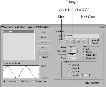
The Period value defines the number of frames required to complete one full pattern. The Amplitude value sets the height of the wave, and the Phase value determines its location at the start of the cycle. The Duty Cycle value is used only for the square wave to define how long it stays enabled.
You can use the Vertical Bias options to set the values range for the waveform. Options include Centered, which sets the center of the waveform at 0; Auto > 0, which causes all values to be positive; Auto < 0, which causes all values to be negative; and Manual, which lets you set a value for the center of the waveform.
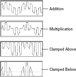
The Effect option determines how different waveforms in the list are combined. They can be added, multiplied, clamped above, or clamped below. The Add option simply adds the waveform values together, and the Multiply option multiplies the separate values. The Clamp Above and Clamp Below options force the values of one curve to its maximum or minimum while not exceeding the values of the other curve. The Characteristic Graph shows the selected waveform, the output, or the final resulting curve. Figure 35.28 shows the Characteristic Graph for each Effect option when a sine wave and a square wave are combined.
FIGURE 35.28 Combining sine and square waves with the Add, Multiply, Clamp Above, and Clamp Below Effect options
Color RGB controller
![]() You can use the Color RGB controller to animate colors. Color values are different from regular float values in that they include three values that represent the amounts of red, green, and blue (referred to as RGB values) present in the color. This data value type is known as Point3.
You can use the Color RGB controller to animate colors. Color values are different from regular float values in that they include three values that represent the amounts of red, green, and blue (referred to as RGB values) present in the color. This data value type is known as Point3.
The Color RGB controller splits a track with color information into its component RGB tracks. You can use this controller to apply a different controller to each color component and also to animate any color swatch in Max.
Cubic Morph controller
You can assign the Cubic Morph controller to a morph compound object. You can find the track for this object under the Objects track. A subtrack of the morph object is the Morph track, which holds the morph keys.
The Cubic Morph controller uses Tension, Continuity, and Bias values to control how targets blend with one another. You can access these TCB values in the Key Info dialog box by right-clicking any morph key or by right-clicking the Morph track and selecting Properties from the pop-up menu.
Note
You also can access the TCB values by right-clicking the keys in the Track Bar.
Barycentric Morph controller
The Barycentric Morph controller is automatically applied when a morph compound object is created. Keys are created for this controller based on the morph targets set in the Modify panel under the Current Targets rollout for the morph compound object. You can edit these keys using the Barycentric controller Key Info dialog box, which you can open by right-clicking a morph key in the Track View or in the Track Bar.
The main difference between the Cubic Morph controller and the Barycentric Morph controller is that the latter can have weights applied to the various morph keys.
The Barycentric Morph controller Key Info dialog box includes a list of morph targets. If a target is selected, its Percentage value sets the influence of the target. The Time value is the frame where this key is located. The TCB values and displayed curve control the Tension, Continuity, and Bias parameters for this controller. The Constrain to 100% option causes all weights to equal 100 percent; changing one value changes the other values proportionally if this option is selected.
Block controller
![]() The Block controller combines several tracks into one block so you can handle them all together. This controller is located in the Global Tracks track. If a track is added to a Block controller, a Slave controller is placed in the track's original location.
The Block controller combines several tracks into one block so you can handle them all together. This controller is located in the Global Tracks track. If a track is added to a Block controller, a Slave controller is placed in the track's original location.
To add a Block controller, select the Available track under the Block Control track under the Global Tracks track, and click the Assign Controller button. From the Assign Constant Controller dialog box that opens, select Master Block and click OK. Right-click the Master Block track and select Properties to open the Master Block Parameters dialog box, shown in Figure 35.29.
FIGURE 35.29 The Master Block Parameters dialog box lists all the tracks applied to a Block controller.
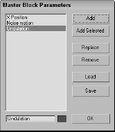
In the Master Block Parameters dialog box, you can add a track to the Block controller with the Add button. All tracks added are displayed in the list on the left. You can give each track a name by using the Name field. You also can use the Add Selected button to add any selected tracks. The Replace button lets you select a new controller to replace the currently selected track. The Load and Save buttons enable you to load or save blocks as separate files.
The Add button opens the Track View Pick dialog box, shown in Figure 35.30. This dialog box displays all valid tracks in a darker color to make them easier to see, while graying out invalid tracks.
FIGURE 35.30 The Track View Pick dialog box lets you select the tracks you want to include in the Block controller.
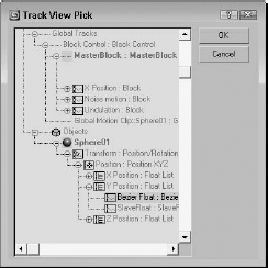
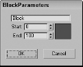
Select the tracks that you want to include, and click OK. The Block Parameters dialog box opens, shown in Figure 35.31, in which you can name the block, specify Start and End frames, and choose a color. Click OK when you're finished with this dialog box.
FIGURE 35.31 The Block Parameters dialog box lets you name a block.
Back in the Master Block Parameters dialog box, click the Load button to open a file dialog box where you can load a saved block of animation parameters. The saved block files have the .blk extension. After the parameters have loaded, the Attach Controls dialog box opens, as shown in Figure 35.32. This dialog box includes two panes. The Incoming Controls pane on the left lists all motions in the saved block. By clicking the Add button, you can add tracks from the current scene, to which you can copy the saved block motions.
FIGURE 35.32 The Attach Controls dialog box lets you attach saved tracks to the Block controller.
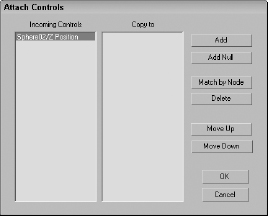
Because the saved motions in the Incoming Controls pane will match up with the Copy to entries in the right pane, the Add Null button adds a space in place of a specific track if you don't want a motion to be copied. The Match by Node button matches tracks by means of the Track View Pick dialog box.
IK controller
The IK controller works on a bones system for controlling the bone objects of an IK (inverse kinematics) system. The IK controller includes many different rollouts for defining joint constraints and other parameters.
Cross-Reference
Find out more about the IK controller in Chapter 38, “Understanding Rigging, Kinematics and Working with Bones.”
Master Point controller
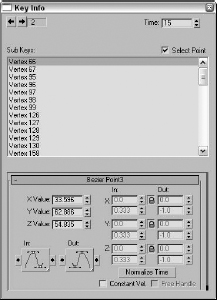
![]() The Master Point controller controls the transforms of any point or vertex subobject selections. The Master Point controller is a controller that you can select and add, but instead it gets added as a track to an object whose subobjects are transformed. Subtracks under this track are listed for each sub-object. The keys in the Master track are colored green.
The Master Point controller controls the transforms of any point or vertex subobject selections. The Master Point controller is a controller that you can select and add, but instead it gets added as a track to an object whose subobjects are transformed. Subtracks under this track are listed for each sub-object. The keys in the Master track are colored green.
Right-clicking a green master key opens the Master Track Key Info dialog box, shown in Figure 35.33. This dialog box shows the Key number with arrows for selecting the previous or next key, a Time field that displays the current frame number, and a list of all the vertices. Selecting a vertex from the list displays its parameters at the bottom of the dialog box.
Summary
The Animation Layers feature provides a simple way to organize animated motions into an easy-to-manage method. The Animation Layers toolbar includes all the tools you need to manage these unique layers. Animation clips for standard objects can be added and mixed in the Motion Mixer. The File ![]() Load Animation option, along with its mapping and retargeting features, lets you reuse saved animations by applying them to other scenes. This chapter also introduced all the available animation modifiers and showed you how to use several of them. Finally, the chapter covered several complex controllers.
Load Animation option, along with its mapping and retargeting features, lets you reuse saved animations by applying them to other scenes. This chapter also introduced all the available animation modifiers and showed you how to use several of them. Finally, the chapter covered several complex controllers.
FIGURE 35.33 The Master Track Key Info dialog box lets you change the key values for each vertex.
In this chapter, you learned about the following:
- Using the Animation Layers toolbar
- Creating new layers and using weights
- Collapsing animation layers
- Loading saved XML animation files
- Remapping animation tracks between objects
- Retargeting to adjust for a change in scale
- Using the Point Cache modifier
- Using the Morpher modifier to deform a face
- Using the Flex modifier and the other deformation modifiers
- Using the various miscellaneous animation modifiers
- Examining the various controllers in several different categories
The next chapter takes a close look at the Expression Controller that gives you the ability to script the controller's behavior. It also covers wiring parameters so that one parameter can control another, and creating custom parameters.