
CHAPTER 40
Skinning Characters
Planning your character
Using the Skin modifier
Painting skin weights
Using the Weight Tool
Working with the Skin Wrap and Skin Morph modifiers
In the taxidermy world, skinning an animal usually involves removing its skin, but in the Max world, skinning a character involves adding a skin mesh to a group of controlling bones. Skinning a character also involves defining how the skin deforms as the bones are moved.
A character skin created in Max can be any type of object and is attached to a biped or a bones skeleton using the Skin modifier. The Skin modifier isn't alone. Max includes other modifiers like the Skin Wrap and Skin Morph modifiers that make your skin portable. This chapter covers how the various Skin modifiers are attached to a skeleton and used to aid in animating your character.
Understanding Your Character
What are the main aspects of your character? Is it strong and upright, or does it hunch over and move with slow, twisted jerks? Before you begin modeling a character, you need to understand the character. It is helpful to sketch the character before you begin. This step gives you a design that you can return to as needed.
Tip
The sketched design also can be loaded and planar mapped to a plane object to provide a guide to modeling.
You have an infinite number of reference characters available to you (just walk down a city street if you can't think of anything new). If you don't know where to start, then try starting with a human figure. The nice thing about modeling a human is that an example is close by (try looking in the mirror).
We all know the basic structure of humans: two arms, two legs, one head, and no tail. If your character is human, then starting with a human character and changing elements as needed is the easiest way to go. As you begin to model human figures, being familiar with anatomy is helpful. Understanding the structure of muscles and skeletal systems helps explain the funny bumps you see in your elbow and why muscles bulge in certain ways.
Tip
If you don't have the model physique, then a copy of Gray's Anatomy can help. With its detailed pictures of the underlying muscular and skeletal systems, you'll have all the details you need without having to pull your own skin back.
The curse and blessing of symmetry
The other benefit of the human body is that it is symmetrical. You can use this to your benefit as you build your characters, but be aware that unless you're creating a band of killer robots, it is often the imperfections in the characters that give them, well, character. Positioning an eye a little off normal might give your character that menacing look you need.
Dealing with details
When you start to model a human figure, you quickly realize that the body includes lots of detail, but before you start naming an object “toenail lint on left foot,” look for details you won't need. For example, modeling toes is pointless if your character will be wearing shoes and won't be taking them off. (In fact, I think shoes were invented so that animators wouldn't have to model toes.)
At the same time, details in the right places add to your character. Look for the right details to help give your character life—a pirate with an earring, a clown with a big, red nose, a tiger with claws, a robot with rivets, and so on.
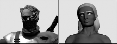
Figure 40.1 shows two good examples. The ninja warrior on the left doesn't need the details of a mouth or teeth because they are hidden behind his mask. In fact, if you were to remove his mask, it would leave a large gaping hole. The Greek woman statue model on the right includes many necessary details including fingernails, toes, a bellybutton, and, uh, well, uh, other details.
Note
You can actually find these two character models on the CD at the back of the book, compliments of Viewpoint Datalabs.
FIGURE 40.1 These two characters have details modeled where needed.
Animated Skin Modifiers
Of all the animation modifiers, several specifically are used to deal with skin. The Skin modifier is a key modifier for enabling character animation. The Skin Morph modifier lets you deform a skin object and create a morph target. It is designed to help fix problem areas, such as shoulders and hips, that have trouble with the standard Skin modifier. The Skin Wrap offers a way to animate a low-res proxy and then apply the same animation to a high-res wrapped object.
Note
A Physique modifier left over from the Character Studio suite of tools has been integrated into Max. The Physique modifier also is used to bind skin meshes to skeletons, but the Skin modifier is easier to use and more powerful. The Physique modifier remains for backward compatibility.
Understanding the skinning process
Unless you like animating using only a skeleton or a biped by itself, a bones system will have a skin attached to it. Any mesh can be made into a skin using the Skin modifier. The Skin modifier is used to bind a skin mesh to a bones system and to define the associations between the skin vertices and the bones. The first step is to bind the skin mesh to the skeleton object. With a skin attached to a bones system, you can move the bones system and the skin follows, but just how well it follows the skeleton's motion depends on a process called skinning.
Cross-Reference
Creating a bones system is covered in more detail in Chapter 37, “Understanding Rigging, Kinematics, and Working with Bones.” Bipeds are covered in Chapter 39, “Animating Characters with CAT.”
Skinning is where you tell which parts of the skin mesh to move with which bones. Obviously, you'd want all the skin vertices in the hand to move with the hand bone, but the skin vertices around the waist and shoulders are trickier.
Each skin area that surrounds a bone gets encompassed by a capsule-shaped envelope. All vertices within this envelope move along with the bone. When two of these envelopes overlap, their surfaces blend together like skin around a bone joint. Most of the skinning process involves getting the skin vertices into the right envelope. The Skin modifier includes several tools to help make this easier, including the Skin Weight table and a painting weights feature.
Binding to a skeleton
After you have both a skeleton and a skin mesh, you need to bind the skin to the skeleton before you can edit the influence envelopes. The binding process is fairly easy: Simply select the skin mesh, and apply the Skin modifier to it using the Modifiers ![]() Animation
Animation ![]() Skin menu command.
Skin menu command.
Tip
Before binding a skeleton to a skin mesh, take some time to match the size and dimensions of the bones close to the skin mesh. The skin mesh is bound to the skeleton, and the envelopes are created automatically. If the bones match the skin, then the new envelopes are pretty close to what they need to be.
In the Parameters rollout, click the Add button above the bones list. This opens a Select Bones dialog box where you can select the bones to use to animate this skin. The selected bones appear in the bones list. The text field directly under the bones list lets you locate specific bones in the list by typing the name. Only one bone at a time may be selected from the list. The Remove button removes the selected bone from the bone list.
Tutorial: Attaching skin to a CAT rig
For human figures, using a biped skeleton saves lots of time. For this example, because he's human in form, you'll bind a biped skeleton to the Future man model.
To bind the skin of a model to a biped skeleton, follow these steps:
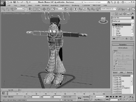
- Open the Marvin Moose CAT rig - final.max file from the Chap 40 directory on the CD.
This file includes the CAT rig built in Chapter 39 for the Marvin Moose character.
- With the CAT rig aligned to the skin mesh, select Unfreeze All from the right-click quadmenu and disable the See-Through option in the Object Properties dialog box. Select the moose model, and choose Modifiers
 Animation Modifiers Skin to apply the Skin modifier.
 - In the Parameters rollout, click the Add button. The Select Bones dialog box opens. Click the All button to select all the bones, and click Select. Don't include the Footsteps, Character001, or the Leg Platform objects.
- In the Parameters rollout, select each of the bones in the list and click the Edit Envelopes button. Zoom in on the highlighted bone (which is the left shin bone), select the cross-section handles for this bone, and set the Radius values to 0.15 near the body and 0.1 for the other end. Figure 40.2 shows the moose skin with all the CAT rig bones added.
FIGURE 40.2 Bone references are added to the skin modifier.
After the Skin modifier is applied and bound to the skin mesh, every bone includes an area of influence called an envelope that defines the skin vertices that it controls. If any of the skin mesh vertices are outside of the bone's envelope or are included in an envelope for the wrong bone, then the vertices are left behind when the bone is moved. This causes an odd stretching of the skin that is easy to identify.
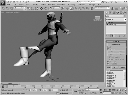
To check the envelopes, select and rotate several of the skeleton's key bones. If any envelope problems exist, they are easy to spot, as shown in Figure 40.3. The incorrect stretching of the vertices for the boot simply means that the envelopes need to be adjusted.
FIGURE 40.3 If the envelopes are off for any of the skin vertices, the skin stretches incorrectly.
Editing envelopes
When the Skin modifier is selected, the Parameters rollout includes an Edit Envelopes button that places you in a special mode that lets you edit the envelope for the selected bone in the bone list. This mode is also enabled by selecting the Envelope subobject under the Skin modifier at the top of the Modifier Stack.
When the Edit Envelopes mode is enabled, the entire skin mesh is colored with a gradient of colors to visually show the influence of the envelope. Areas of red are completely inside the envelope's influence, areas of green are somewhat affected by the bone, and areas of gray are completely outside the envelope's influence.
Figure 40.4 shows a simple loft object surrounding three bone objects with a Skin modifier applied. The Add Bone button was used to include the three bones within the Skin modifier list. The skin has been set to See Through in the Properties dialog box, so the bones are visible. The first bone was selected in the bone list, and the Edit Envelope button was clicked, revealing the envelope for the first bone.
FIGURE 40.4 Envelopes define which Skin vertices move with the underlying bone.
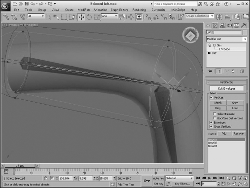
An envelope consists of two capsule-shaped volumes within each other called the Inner and Outer Envelopes. Any vertices within the inner envelope are controlled exclusively by that bone. Any vertices positioned between the inner and outer envelopes are controlled by a falloff where the influence is shared between bones.
At either end of these envelopes are four small handles that can be dragged to change the cross-section radius. The cross-section area changes to pink when selected. The radius of the selected cross section is displayed in the Radius field within the Envelope Properties section of the Parameters rollout. The Squash value determines the amount of squash applied to the object for bones that can stretch. You can change an envelope's size by changing its Radius value or by dragging the cross-section handles. Within the Select section of the Parameters rollout, you can choose to select and edit Vertices, Envelopes, and/or Cross Sections. If you choose the Vertices option, selected vertices are shown as small squares, and the Shrink, Grow, Ring, and Loop buttons become active. These buttons allow you to select a desired set of vertices easily. If the Select Element option is enabled, then all vertices in the element are selected, and the Backface Cull Vertices option prevents vertices on the backside of the object from being selected.
If a cross section is selected, you can add a different cross-section shape using the Add button. This button lets you select a cross-section shape within the viewports. The Remove Cross Section button removes an added cross section from the envelope.
Note
The orientation of the envelope spline is set by the longest dimension of the bone. This works well for arm and leg bones, but the pelvis or clavicle may end up with the wrong orientation.
The Envelope Properties section of the Parameters rollout (just below the Radius and Squash buttons) includes five icon buttons, shown in Table 40.1. The first toggles between Absolute and Relative. All vertices that fall within the outer envelope are fully weighted when the Absolute toggle is set, but only those within both envelopes are fully weighted when the Relative toggle is selected.
TABLE 40.1 Envelope Properties
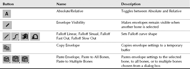
The second icon button enables envelopes to be visible even when not selected. This helps you see how adjacent bones overlap. The third icon button sets the Falloff curve for the envelopes. The options within this flyout are Linear, Sinual, Fast Out, and Slow Out. The last two icon buttons can be used to Copy and Paste envelope settings to other bones. The flyout options for the Paste button include Paste (to a single bone), Paste to All Bones, and Paste to Multiple Bones (which opens a selection dialog box).
Working with weights
For a selection of vertices, you can set its influence value (called its Weight value) between 0 for no influence and 1.0 for maximum influence. This provides a way to blend the motion of vertices between two or more bones. For example, the vertices on the top of a character's shoulder could have a weight value of 1.0 for the shoulder bone, a weight value of 0.5 for the upper arm bone, and a weight value of 0 for all other bones. This lets the shoulder skin area move completely when the shoulder bone moves and only halfway when the upper arm moves.
The shading in the viewport changes as vertices are weighted between 0 and 1. Weight values around 0.125 are colored blue, weight values around 0.25 are colored green, weight values around 0.5 are colored yellow, and weight values around 0.75 are colored orange.
The Absolute Effect field lets you specify a weight value for the selected vertices. The Rigid option makes the selected vertices move only with a single bone. The Rigid Handles causes the handles of the selected vertices for a patch object to move only with a single bone. This is important if the character is wearing a hard item such as armor plates. By enabling this option, you can be sure that the armor plate doesn't deform. The Normalize option requires that all the weights assigned to the selected vertices add up to 1.0.
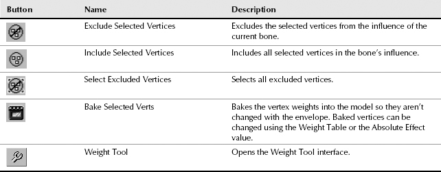
The other buttons found in the Weight Properties section of the Parameters rollout are defined in Table 40.2. Include Vertices and Exclude Vertices buttons let you remove the selected vertices from those being affected by the selected bone. The Select Exclude Verts button selects all excluded vertices.
TABLE 40.2 Envelope Properties
Using the Weight Tool
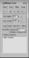
The Weight Tool button in the Parameters rollout opens the Weight Tool dialog box, shown in Figure 40.5. The Shrink, Grow, Ring, and Loop buttons work the same as those in the Select section, and they let you quickly select precise groups of vertices. The value buttons on the second row allow you to change weight values with a click of the button or by adding or subtracting from the current value.
The Copy, Paste, and Paste Position buttons let you copy weights between vertices quickly. The Paste Position button pastes the given weight to the surrounding vertices based on the Tolerance value. The Blend button quickly blends all the surrounding vertices from the current weight value to 0, creating a smooth blend weight. The Weight Tool dialog box also lists the number of vertices in the copy buffer and currently selected. The list at the bottom of the dialog box lists the weight and bone for the selected vertices.
FIGURE 40.5 The Weight Tool dialog box includes buttons for quickly altering weight values and for blending the weights of adjacent vertices.
Using the Weight Table
The Weight Table button opens the Weight Table interface, shown in Figure 40.6. This table displays all the vertices for the skinned object by ID in a column on the left side of the interface. All bones are listed in a row along the top. For each vertex and bone, you can set a weight.
FIGURE 40.6 The Weight Table lets you specify weight values for each vertex and for each bone.
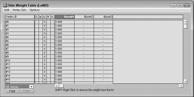
The Edit menu includes commands to Copy and Paste weights. It also includes commands to Select All, Invert, and None. A selection of vertices can be combined into a Vertex Set and named. The Vertex Sets menu lets you create and delete these sets.
The Options menu lets you flip the interface so that bones are displayed in the first column and the vertex IDs are along the top row. The Update On Mouse Up option limits the updates until the mouse is released. Several options for showing and hiding interface elements are included. The Show Affected Bones option lists only the bones that are affected. The Show Attributes option displays a column of attributes labeled S, M, N, R, and H. The Show Exclusions option makes a check box available in each cell. When checked, the vertex is excluded. The Show Global option makes a drop-down list available that enables you to set an attribute for all vertices. The Show Locks option (like the Show Exclusions option) makes a check box available for each cell. Enabling this check box (the left one) locks the weight so it can't change. The Set Sets UI makes available two buttons for creating and deleting vertex sets.
The S attribute is marked if a vertex is selected, the M attribute marks a vertex weight that has been modified, the N attribute marks a normalized weight, the R attribute marks rigid vertices, and an H attribute marks a vertex with rigid handles.
To set a weight, just locate the vertex for the bone, click in the cell, and type the new value. If you click a cell and drag to the left or right, the weight value changes. Weight values can be dragged between cells. Right-clicking a cell sets its value to 0, and right-clicking with the Ctrl key held down sets its value to 1.0.
After the vertex weights are set, you can click the Bake Selected Vertices to lock down the weight values. Changes to envelopes do not affect baked vertices.
Painting weights
Using the Paint Weights button, you can paint with a brush over the surface of the skin object. The Paint Strength value sets the value of each brush stroke. This value can be positive (up to 1.0) for vertices that will move with the bone or negative (to −1.0) for vertices that will not move with the bone.
To the right of the Paint Weights button is the Painter Options button (it has three dots on it), which opens the Painter Options dialog box.
Cross-Reference
The Painter Options dialog box also is used by the Vertex Paint modifier and the Paint Deformation tool. It is described in detail in Chapter 13, “Modeling with Polygons.”
Tutorial: Applying skin weights
In this example, you change the skin weights of the future man character in an attempt to fix the problem you saw with his boots.
To apply the skin weights to a character, follow these steps:
- Open the Future man with skin final.max file from the Chap 40 directory on the CD.
- With the mesh skin selected, open the Modify panel and choose the Bip01 L Foot bone in the bone list. Then click the Edit Envelopes button at the top of the Parameters rollout. This displays the envelopes around the foot object. Zoom in on the foot object, and change the display option to Realistic or press the F3 key, so you can see the weight shading.
- Make sure the Cross Sections option in the Select section of the Parameters rollout is selected. Then select the cross-section handles on the outer envelope and pull them in toward the foot. Rotate the side to make sure that the toe and heel of the boot are still covered.
- Click the Vertices option in the Parameters rollout, and disable the Backface Cull Vertices option. Drag over all the vertices that are contained in the lower part of the boot, and enable the Rigid option. Then select the vertices above the boot in the shin. You can use the Loop button to select all vertices about the upper part of the boot and press and hold the Alt key to remove any vertices that are part of the lower boot.
- In the Weight Properties section of the Parameters rollout, click the Weight Tool button. In the Weight Tool dialog box, click the .25 button. This changes the weight of the selected vertices. Then click the Blend button to smooth the transition areas.
- Click the Edit Envelopes button to exit Edit Envelopes mode. Then select and rotate the upper leg to see whether the problem has been fixed. As I rotated my model, I noticed that some vertices on the back of the boot were left behind, which means that they aren't being influenced by the foot bone.
Caution
Be sure to undo the upper leg rotation before making changes to the envelopes, or the envelopes will move along with the rotation.
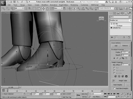
- Enter Edit Envelopes mode again, and click the Paint Weights button. The cursor changes to a round brush. Click the Brush Options button (which is next to the Paint Weights button with three dots). This opens the Brush Options dialog box. Set the Max Strength value to 1.0, and close the dialog box. Then paint in the viewport over the vertices on the back of the boot heel, including those areas that aren't shaded red. Figure 40.7 shows the correct boot with its envelopes.
- Exit Edit Envelopes mode again, and check the changes by rotating the upper leg bone.
FIGURE 40.7 Vertices’ weights can be fixed with the Weight Tool and by Painting Weights.
Mirror settings
Most characters have a natural symmetry, and you can use this symmetry to mirror envelopes and vertex weights between different sides of a model. You can use this feature by clicking the Mirror Mode button in the Mirror Parameters rollout. This button is active only when the Edit Envelope button is active.
In Mirror Mode, you see an orange plane gizmo that marks the symmetrical line for the model. You can move and orient this plane using the Mirror Offset and Mirror Plane controls. Once oriented, Max computes the matching vertices based on the volumes from the mirror plane. All vertices on one half of the character appear blue, and all the matching vertices appear green. All vertices that cannot be matched appear red.
If you drag over bones or vertices in the viewports, you can select them. Clicking the Mirror Paste button pastes the envelopes and vertex weights of the selected vertices to their matches. Or you can select the Paste Green to Blue Bones button or one of its neighbors to copy all the green bones or vertices to their matches, or vice versa.
The Display Projection drop-down list projects the position of the selected vertices onto the Mirror Plane so you can compare their locations relative to each other. With lots of vertices in your skin, you want to enable the Manual Update, or the viewport refreshes become slow.
Tutorial: Mirroring skin weights
Now that you have spent the time correcting the skin weights for the left boot, you use the Mirror Weights feature to apply the same weights to the opposite foot.
To apply the skin weights to a character, follow these steps:
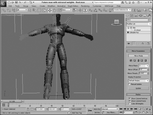
- Open the Future man with corrected weights - final.max file from the Chap 40 directory on the CD.
- With envelope mode turned on, select the Bip01 L Foot bone from the list in the Parameters rollout, and click the Mirror Mode button in the Mirror Parameters rollout. An orange gizmo is added to the viewport that divides the model, as shown in Figure 40.8.
- Drag over all the vertices that make up the left boot, and then click the Paste Blue to Green Verts button. All the vertex weights on the left side of the model are copied to the right side. The pasted vertices turn yellow once pasted.
Display and Advanced settings
The Display rollout controls which features are visible within the viewports. Options include Show Colored Vertices, Show Colored Faces, Color All Weights, Show All Envelopes, Show All Vertices, Show All Gizmos, Show No Envelopes, Show Hidden Vertices, Draw On Top Cross Sections, and Draw On Top Envelopes.
With these display options, you can turn on and off the weight color shading on vertices and faces. You can also select to show all envelopes, vertices, and gizmos. The Color All Weights option is unique. It assigns every bone a different color and shows how the weights blend together between bones.
FIGURE 40.8 In Mirror mode, matched bones and vertices appear green and blue.
The Advanced Parameters rollout includes an option to Back Transform Vertices. This option avoids applying transform keys to the skin because the bones control the motion. The Rigid Vertices and Rigid Patch Handles options set the vertices so that they are controlled by only one bone. This rollout also includes buttons to Reset Selected Vertices, Reset Selected Bones, and Reset All Bones. This is handy if you really mess up a skinning job, because it gives you a chance to start over. It also includes buttons for saving and loading envelopes. The envelopes are saved as files with the .env extension.
The Animatable Envelopes option lets you create keys for envelopes. Weight All Vertices is a useful option that automatically applies a weight to the nearest bone of all vertices that have no weight. The Remove Zero Weights button removes the vertex weight of any vertex that has a value lower than the Zero Limit. This can be used to remove lots of unnecessary data from your model if you need to put it on a diet.
Using deformers
Below the Advanced Parameters rollout is the Gizmos rollout. You use this rollout to apply deformers to selected skin object vertices. Three deformers are available in the Gizmos rollout: a Joint Angle Deformer, a Bulge Angle Deformer, and a Morph Angle Deformer.
Each of these deformers is unique. They include the following features:
- Joint Angle Deformer: Deforms the vertices around the joint between two bones where the skin can bunch up and cause problems. This deformer moves vertices on both the parent and child bones.
- Bulge Angle Deformer: Moves vertices away from the bone to simulate a bulging muscle. This deformer works only on the parent bone.
- Morph Angle Deformer: Can be used on vertices for both the parent and child bones to move the vertices to a morph position.
All deformers added to a skin object are listed in the Gizmo rollout. You can add deformers to and remove deformers from this list using the Add and Remove Gizmo buttons. You can also Copy and Paste the deformers to other sets of vertices. Before a deformer gizmo can be applied, you need to select vertices within the skin object. To select vertices, enable the Vertices check box of the Parameters rollout and drag over the vertices in the viewport to select the vertices.
The parameters for the deformer selected in the Gizmo rollout's list appear when the deformer is selected in the Deformer Parameters rollout. This rollout lists the Parent and Child bones for the selected vertices and the Angle between them. This rollout changes depending on the type of deformer selected.
For the Joint and Bulge Angle Deformers, a new rollout labeled Gizmo Parameters or Deformer Parameters appears. The Gizmo Parameters rollout includes buttons to edit the control Lattice and to edit the deformer Key Curves. The Edit Lattice button lets you move the lattice control points in the viewports. The Edit Angle Keys Curves opens a Graph window that displays the transformation curves for the deformation.
Using the Skin Wrap modifiers
If you've created a high-resolution model that you want to animate as a skin object, but the mesh is too complex to move around, then the Skin Wrap modifier might be just what you need. The Skin Wrap modifier may be applied to a high-resolution mesh, and with the Parameters rollout you can select a low-resolution control object. Any movements made by the low-resolution control object automatically are applied to high-resolution mesh.
Tip
Skin Wrap is also very useful for animating clothes on a character.
The Skin Wrap modifier has two available Deformation Engines: Face Deformation and Vertex Deformation. Each vertex contained with the control object acts as a control vertex. The Vertex Deformation option moves the vertices closest to each control vertex when the control vertex is moved, and the Face Deformation option moves the faces that are closest.
For each deformation mode, you can set a Falloff value, which moves vertices farther from the moved control vertex to a lesser extent to ensure a smoother surface. For the Vertex Deformation mode, you can also set a Distance Influence value and Face Limit values to increase the extent of influence for a control vertex.
The Reset button can be used to reset the control object to the high-resolution mesh object. This is useful if you need to realign the control object to the Skin Wrap object. When you're finished animating the control object, the Convert to Skin button may be used to transfer the animation keys to the high-resolution objects.
The Advanced Parameters rollout includes a button for mirroring the selected vertices to the opposite side of the control object.
The Modifiers menu also includes a Skin Wrap Patch modifier, which works the same as the Skin Wrap modifier, but it allows the control object to be a patch.
Tutorial: Making a simple squirt bottle walk
Creating a bones structure and applying a Skin modifier works well for characters with structure, but to animate the motion of an amorphous object such as a squirt bottle, the Skin Wrap modifier works much better than bones.
To animate a squirt bottle object walking using the Skin Wrap modifier, follow these steps:
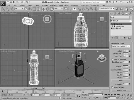
- Open the Walking squirt bottle.max file from the Chap 40 directory on the CD.
This file includes a squirt bottle model with all its parts attached together. The file also includes a simple box object that is roughly the same shape as the squirt bottle. The box object has been animated walking forward.
- With the squirt bottle object selected, choose the Modifiers Animation Skin Wrap menu command to apply the Skin Wrap modifier.
- In the Parameters rollout, click the Add button and select the Box object. The Box object is added to the Skin Wrap list in the Parameters rollout.
- Select the Box object and hide it in the scene.
- Click the Play Animation button, and the hi-res bottle follows the same animation as the box object.
Figure 40.9 shows the squirt bottle as it moves through the scene.
FIGURE 40.9 Not all animated objects need a bone structure.
Using the Skin Morph modifier
Using the deformation options found in the Skin modifier, you can deform any part of the skin, but this feature relies on using gizmos found in an already complex envelope-editing mode. Skin Morph offers another way to deform a skin object using the underlying bones. The Skin Morph modifier is applied on top of a Skin modifier and lets you pick which bones to use in the deformation. For example, for bulging muscles, the forearm bone is rotated and should be added to the list in the Parameters rollout.
After selecting a bone from the Parameters rollout list, select the frame where the deformation is at a maximum. Then click the Create Morph button in the Local Properties rollout to create the morph target. Morph targets can be given names to make them easy to select later. The Edit button in the Local Properties rollout then lets you move the vertices for the deformation.
Tutorial: Bulging arm muscles
Perhaps the most common bulging deformation for characters is making the bicep muscle bulge as the forearm is raised. This effect can be simplified using the Skin Morph modifier.
To bulge an arm muscle using the Skin Morph modifier, follow these steps:
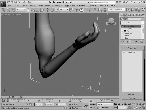
- Open the Bulging bicep.max file from the Chap 40 directory on the CD.
This file includes a rough arm model with a Skin modifier applied attached to a four-bone chain.
- With the arm skin selected, choose the Modifiers Animation Skin Morph menu command to apply the Skin Morph modifier on top of the Skin modifier.
- In the Parameters rollout, click the Add Bone button and select the forearm bone object.
The bone object is added to the Skin Morph list in the Parameters rollout.
- Select and rotate the forearm bone to the location where the deformation is at its maximum. Then select the bone object from the list in the Parameters rollout, and click the Create Morph button in the Local Properties rollout. In the Morph Name window name the morph Bulging bicep.
Tip
The forearm bone can be hard to see under the skin, but you can always select the bone using the Select by Name dialog box, which is opened by pressing H.
- In the Local Properties rollout, click the Edit button. This enables the Points subobject mode. Then enable the Edge Limit option in the Selection rollout, so the vertices on the forearm aren't accidentally selected. Drag over the points on the front of the bicep muscle in the Left viewport, and enable the Use Soft Selection option in the Selection rollout. Set the Radius value to 0.5, and scale the points to the right in the Left viewport to form a bulge. Click the Edit button again to exit Edit mode.
- Select and rotate the forearm bone to see the bulging bicep muscle.
Figure 40.10 shows the arm muscle as it bulges along with the rotating forearm.
FIGURE 40.10 Using the Skin Morph, you can set a muscle to bulge as the forearm is rotated.
Using Character Animation Techniques
When it comes to character animation, several techniques can really help. Keeping these points in mind as you animate characters can make a difference:
- Use Biped: Manual rigging is useful for those cases where Biped won't work, but the tools and features found in Biped make it silly to look elsewhere for human characters.
- Use dynamics: Dynamic packages like reactor can provide incredibly realistic motion based on physical properties. Learning to use this powerful tool for even the most basic animation sequences is worth the effort.
- Learn by example: If you're working on a cartoon character, then by all means, watch cartoons. Traditional cartoons understand and invented the language of cartoon motion, including squash and stretch, exaggerated motion, or scaling eyes large to indicate surprise. If your character motion is more realistic, find the motion, videotape it, and watch it over and over to catch the subtle secondary motion.
- Use background animations: The Viewport Background can load animation clips, which can make positioning characters to match real motion easy. This is a poor man's motion capture system.
- Include secondary motion: The primary motion of a character is often the main focus, but you can enhance the animation by looking for secondary motion. For example, when a person walks, you see his legs take the steps and his arms moving opposite the legs’ motion, but secondary motion includes his hair swishing back and forth and shoelaces flopping about.
- Use the Flex modifier: The Flex modifier gives soft bodies, such as tails, hair, ears, and clothing, the realistic secondary motion needed to make them believable.
- Use the Morph modifier: The Morph modifier can be used to morph a character between two poses or to morph its face between the different phonemes as the character talks.
- Use IK: The next chapter covers this in detail, but here's a quick tip: Having a character move by positioning its foot or hand is often much easier than pushing it into position.
- Use the Spring Controller: Another good way to get secondary motion is to use the Spring Controller. This controller works well with limbs.
- Add randomness with the Noise Controller: Often, perfect animation sequences don't look realistic, and using the Noise Controller can help to make a sequence look more realistic, whether the Noise Controller is applied to a walking sequence or to the subtle movement of the eyes.
- Use manipulators: Manipulators can be created and wired to give you control over the animation values of a single motion, such as opening and closing the character's eyes.
Summary
Characters are becoming more and more important in the Max world and can be saved as separate files just like Max scene files. Combining a detailed skin mesh with a skeletal biped lets you take advantage of Character Studio's unique animation features. This chapter covered the following topics:
- Designing your character before building
- Working with the Skin modifier
- Reusing animations with Skin Wrap
- Bulging muscles with Skin Morph
In Part X, “Dynamic Animation,” you'll examine the dynamic animation features, starting with particle systems.