
CHAPTER 45
Working with Advanced Lighting, Light Tracing, and Radiosity
Using advanced lighting
Understanding light tracing
Setting local advanced lighting parameters
Understanding radiosity
Setting global advanced lighting parameters
Using the Advanced Lighting materials and the Lighting Analysis Assistant
If you were to walk into a dark room and reach for the light switch, you would be confused if you found a separate switch that controlled the advanced lighting. But in Max the advanced lighting controls are worth the trouble. They enable you to take your lighting solution to the next level.
The advanced lighting controls in Max enable you to light scenes using two separate global illumination techniques known as light tracing and radiosity. Both solutions deal with the effect of light bouncing off objects and being reflected to the environment.
Light tracing is typically used for outdoor scenes where the light consists of a single powerful light source at a far distance from the scene. Light tracing includes support for color bleeding between surfaces. Another aspect of light tracing is that the shadows are softer.
Radiosity computes lighting solutions that are much more realistic than using standard lights. As you learn to use radiosity, you quickly discover that it is a complex system that takes lots of tweaking to get just right.
Selecting Advanced Lighting
You control the advanced lighting settings for the scene in the Advanced Lighting panel, which is part of the Render Scene dialog box. You can access this panel by selecting Rendering ![]() Light Tracer or Rendering
Light Tracer or Rendering ![]() Radiosity (or by pressing the 9 key). The Advanced Lighting panel includes a rollout with a single drop-down list where you can select the lighting plug-in to use. The options are None, Light Tracer, and Radiosity.
Radiosity (or by pressing the 9 key). The Advanced Lighting panel includes a rollout with a single drop-down list where you can select the lighting plug-in to use. The options are None, Light Tracer, and Radiosity.
Light Tracer and Radiosity are two different techniques for applying advanced lighting to a scene. Although they are fundamentally different, they both simulate a critical piece of the lighting puzzle that adds dramatically to the realism of the lights in the scene—light bouncing. When light strikes a surface in real life, a portion of the light bounces off the surface and illuminates other surfaces. Traditionally, Max hasn't worried about this, which required that users add more lights to the scene to account for this additional lighting. Both the Light Tracer and the Radiosity solutions include light bouncing in their calculations.
How light tracing works
The Light Tracer is a Global Illumination (GI) system that is similar to raytracing, but it focuses more on calculating how light bounces off surfaces in the scene. The results are fairly realistic without being computationally expensive, and its solutions are rendered much quicker than a radiosity solution.
Cross-Reference
The Light Tracer is similar in many ways to raytracing. Chapter 47, “Rendering with mental ray and iray,” presents more information on raytracing.
The Light Tracer works by dividing the scene into sample points. These sample points are more heavily concentrated along the edges of objects in the scene. An imaginary light ray is then shot at each sample point, and the light intensity at the location of contact is recorded; then it is computed where the light ray would bounce to, and a reduced intensity value is recorded. One of the settings is how many times the light rays will bounce within the scene, and this value increases the amount of time required to compute the solution. When all the rays and light bounces have been computed, the total light intensity value for each sample point is totaled and averaged.
Caution
Transparent objects split each ray in two. One ray bounces, and the second ray is projected through the transparent object. Transparent objects in the scene quickly double the amount of time required to compute a solution.
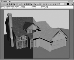
The end result of a light tracing solution is that objects that are typically hidden in the shadows become much easier to see. Figure 45.1 shows a house model that was rendered using the standard lighting solution with raytraced shadows and then again using the Light Tracer opened side by side in the RAM Player. Notice that many of the details hidden in the shadows of one figure are visible in the other.
FIGURE 45.1 A house scene rendered using standard lighting (left) and light tracing (right)
Enabling light tracing
To enable light tracing in a scene, select Rendering ![]() Light Tracer to open the Advanced Lighting panel in the Render Scene dialog box, as shown in Figure 45.2.
Light Tracer to open the Advanced Lighting panel in the Render Scene dialog box, as shown in Figure 45.2.
FIGURE 45.2 The Light Tracer Parameters rollout sets values for GI lighting.
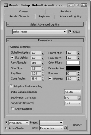
The Global Multiplier value increases the overall effect of the Light Tracer, much like increasing the multiplier of a light. The net result is to brighten the scene. You also can increase the multiplier of skylights with the Sky Lights values. The Object Multiplier sets the amount of light energy that bounces off the objects.
Color bleeding
Another characteristic of global illumination is color bleeding. As a light ray strikes the surface of an object and bounces, it carries the color of the object that is struck with it to the next object. The result of this is that colors from one object bleed onto adjacent objects. You can control this effect using the Color Bleed setting. You can greatly exaggerate the amount of color bleeding by increasing the Object Multiplier along with the Color Bleed value. You also can select colors to use for a color filter and for extra ambient light.
Note
The color bleeding effect doesn't happen unless the Bounce value is set to 2 or greater.
When using color bleeding, you also want to enable the Exposure Control to the scene. Exposure Control is found in the Environment panel (keyboard shortcut, 8), which can be opened with the Rendering ![]() Environment menu command.
Environment menu command.
Tip
When changing the Exposure Control settings, you can get a quick preview of the scene by clicking the Render Preview button in the Exposure Control rollout of the Environments and Effects dialog box.
Cross-Reference
The Exposure Control features are discussed in Chapter 23, “Rendering a Scene and Enabling Quicksilver.”
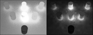
Figure 45.3 shows an example of color bleeding with several colored cylinders projecting from a gray Box object. The Object Multiplier value was set to 4.0, and the Color Bleed was set a maximum value of 25.0 with a Bounce value of 3. Using the Exposure Control settings, you can isolate the color bleed.
FIGURE 45.3 Color bleeding spreads color about the scene. Exposure Control can highlight it with Automatic (left) and Logarithmic (right).
Quality versus speed
The big trade-off of global illumination is between quality and render time. The more rays per sample that you specify, the better the quality and the longer the render time. This is controlled with the Rays/Sample setting. The Rays/Sample setting and the number of Bounces dramatically increase the rendering time. The Ray Bias setting biases rays toward object edges versus flat areas.
Tip
If you want to see a preview of your scene using light tracing, set the Rays/Sample value to around 10 percent of its normal value and render the scene. The resulting image is grainy, but it shows a rough approximation of the scene lighting without having to change the Bounce value.
If you don't include enough rays in the scene, then noise patterns appear within the scene. The Filter Size can help control the amount of noise that appears in the scene.
The number of Bounces value specifies the number of times the ray bounces before being dropped from the solution. A setting of 0 is the same as disabling the Light Tracer, and the maximum value of 10 requires a long time to compute. The Cone Angle defines the cone region within which the rays are projected. The Volumes option is a multiplier for the Volume Light and Volume Fog atmosphere effects.
Adaptive undersampling
With the Adaptive Undersampling option enabled, the Light Tracer focuses on the areas of most contrast, which usually occur along the edges of objects. When this option is enabled, you can specify the spacing of the samples and how finely the samples get subdivided. The Initial Sample Spacing options range from 1 × 1 to a very dense 32 × 32. The Subdivision Contrast affects the density for contrast edges between objects and shadows. This value is a minimum amount of contrast that is allowed. If the amount of contrast is greater than this value, then the area is further subdivided into more samples. These high-contrast areas use the Subdivide Down To setting. The Show Samples option displays each sample as a red dot on the rendered image.
Tutorial: Viewing color bleeding
One of the easiest effects of the Light Tracer to see is color bleeding. Although this is often undesirable, it is a telltale sign of global illumination.
To compare the differences between a regular rendering and the Light Tracer, follow these steps:
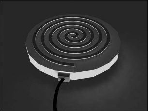
- Open the Hotplate.max file from the Chap 45 directory on the CD.
This file includes a simple model of a hotplate.
- Open the Advanced Lighting panel by selecting Rendering
 Light Tracer (or press the 9 key). In the Parameters rollout, set the Object Multiplier to 10, the Color Bleed to 25, and the Bounces to 1.
 - Select the Rendering Environment (8) menu command to open the Environment and Effects panel. In the Exposure Control rollout, select the Linear Exposure Control option and enable the Process Background and Environment Maps option. In the Linear Exposure Control Parameters rollout, adjust the Brightness to 40 and click the Render Preview button to see a quick preview of the results in the Exposure Control rollout.
- In the Render Scene dialog box, click the Render button.
This renders the scene in the Rendered Frame Window.
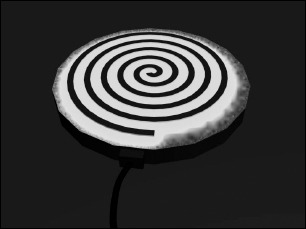
Figure 45.4 shows the scene rendered with advanced lighting.
FIGURE 45.4 Color bleeding happens only when global illumination is enabled.
Using Local Advanced Lighting Settings
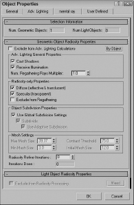
You can set advanced lighting settings locally for specific objects using the Object Properties dialog box, as shown in Figure 45.5.
At the top of the Advanced Lighting panel in the Object Properties dialog box is the number of selected objects and lights. The Object Properties dialog box is opened using Edit ![]() Object Properties. This dialog box lets you specify whether this object should be excluded from the advanced lighting calculations. The properties can be set By Object or By Layer. If included, you can select whether the object casts shadows, whether it receives illumination, and how it handles radiosity. The Number Regathering Rays Multiplier option sets the number of rays cast by the selected object. For large, smooth surfaces, reducing artifacts by increasing this value can be helpful. The remaining settings in this panel deal with radiosity.
Object Properties. This dialog box lets you specify whether this object should be excluded from the advanced lighting calculations. The properties can be set By Object or By Layer. If included, you can select whether the object casts shadows, whether it receives illumination, and how it handles radiosity. The Number Regathering Rays Multiplier option sets the number of rays cast by the selected object. For large, smooth surfaces, reducing artifacts by increasing this value can be helpful. The remaining settings in this panel deal with radiosity.
FIGURE 45.5 Use the Advanced Lighting panel in the Object Properties dialog box to disable advanced lighting.
Tutorial: Excluding Objects from Light Tracing
Using the Object Properties dialog box, you can exclude certain objects from the light tracing calculations.
To exclude objects from the Light Tracer, follow these steps:
- Open the Hotplate.max file from the Chap 45 directory on the CD.
This file includes a simple model of a hotplate.
- Open the Advanced Lighting panel by selecting Rendering Light Tracer (or press the 9 key). In the Parameters rollout, set the Bounces value to 2.
- In the Front viewport, select the plug, cord, and floor objects, and then select Edit Object Properties to open the Properties dialog box for these objects. In the Object Properties dialog box, open the Advanced Lighting panel and enable the Exclude from Advanced Lighting Calculations option. Then click OK.
- In the Render Scene dialog box, click the Render button.
This renders the scene in the Rendered Frame Window.
Figure 45.6 shows the scene rendered with advanced lighting that excludes certain objects.
FIGURE 45.6 Color bleeding becomes much stronger with a higher Bounce value.
Understanding Radiosity
Imagine a scene that includes an umbrella with a light source directly overhead. If you rendered the scene, the object caught in the umbrella's shadow would be too dark for you to see clearly. To fix this situation, you would need to add some extra lights under the umbrella and set them to not cast shadows. Although this workaround provides the solution you want, it is interesting to note that this isn't the case in real life.
The difference between the workaround and real life has to do with the effect of light energy being reflected (or bounced) off the lit objects. It is this phenomenon that allows me to look down the hall and see whether my children's light is still on past bedtime. Even though I can't see the light directly, I know it is on because of the light that reflects off the other walls.
Radiosity is a lighting algorithm that is based on how heat or energy transfers across surfaces. Every time a bit of light energy, called a photon, strikes a surface, the light energy is reduced, but the light energy is bounced onto the surrounding faces. The greater the number of bounces that are computed, the more realistic the lighting solution, but the longer it takes to compute. So, using radiosity, the objects under the umbrella are visible even if they are in the shadows. Because of the way the light is computed, radiosity solutions are not capable of generating direct specular highlights.
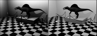
Radiosity is mostly used to light indoor scenes because that is where the effect of light bouncing is most evident. Radiosity, along with light tracing, is another method for computing global illumination. Figure 45.7 shows the dinosaur exhibit in a museum with and without radiosity. Notice how dark the shadows are in the normal lighting image.
FIGURE 45.7 This scene is lighted using normal lighting (left) and radiosity lighting (right).
Lighting for radiosity
The Advanced Lighting panel in Max includes Light Tracing and Radiosity options. You can choose either option from the Advanced Lighting panel in the Render Scene dialog box. You can open this panel with the Radiosity option selected using the Rendering ![]() Radiosity menu command. Pressing the 9 key opens the Render Scene dialog box with the Advanced Lighting panel open.
Radiosity menu command. Pressing the 9 key opens the Render Scene dialog box with the Advanced Lighting panel open.
Radiosity lighting is not displayed until you have Max compute it by clicking the Start button in the Radiosity Processing Parameters rollout. After a radiosity solution is calculated, the results are saved as light maps. These maps are easy to apply to a scene and can be viewed within the viewports. However, when the geometry or lights of the scene change, you need to recalculate the lighting solution.
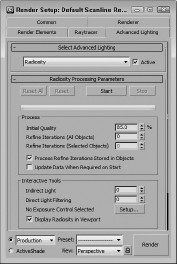
The Radiosity Processing Parameters rollout, shown in Figure 45.8, lets you set the quality of the radiosity solution. You also can specify the number of iterations to use for the scene and for the selected objects. These are different steps in the radiosity computation. The Initial Quality defines the accuracy of the rays that are bounced around the scene. This stage sets the brightness for the scene. The Refine Iterations improves the general quality of the lighting solution for each iteration. You can refine iterations only for the selected object. This lets you target the iterations instead of computing them for the entire scene.
The Interactive Tools section lets you specify a Filtering value. A greater Filtering value eliminates noise between adjacent surfaces by averaging the lighting coming from all surrounding surfaces. The Setup button offers access to the Exposure Control rollout in the Environment panel. You also can turn off radiosity in the viewports.
Cross-Reference
Chapter 23, “Rendering a Scene and Enabling Quicksilver,” includes coverage of the Exposure Control rollout.
Subdividing a mesh for radiosity
As you begin to play with radiosity, you'll quickly find that to get accurate results, you need to have good, clean models. If any models have long, thin faces, then the results are unpredictable.
The Radiosity Meshing Parameters rollout includes an option to enable meshing and a Meshing Size value. This setting is the same as the Size value parameter for the Subdivide modifier, except that it is applied globally.
FIGURE 45.8 The Radiosity Processing Parameters rollout includes buttons for computing a solution.
Tip
If you're creating an indoor room using the Box object, be aware that Box objects have only one external face surface with normals, so the interior of a Box object will not have the correct lighting. You can easily fix this by applying the Shell modifier to the Box object. This adds an interior set of faces to the Box object.
Using the Subdivide modifier
The Modifiers menu includes a submenu for Radiosity modifiers. This submenu includes only the Subdivide modifier and a World-Space version of the Subdivide modifier. This modifier accomplishes a simple task—creating a mesh that has regular, equally shaped triangular faces that work well when computing a radiosity solution.
Tip
Although this modifier was created to help with radiosity solutions, it also helps with other commands that require regular mesh faces, such as the Boolean and Terrain compound objects.
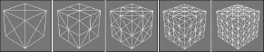
The Parameters rollout includes a Size value that determines the density of the mesh. The lower the value, the denser the mesh and the better the resulting radiosity solution, but the longer the solution takes. This same Subdivision Size setting also can be found (and set globally) in the Radiosity Meshing Parameters rollout of the Advanced Lighting panel. It is also found in the Advanced Lighting panel of the Object Properties dialog box. Figure 45.9 shows a simple cube with the Subdivide modifier applied and the Size value set to (from left to right) 50, 30, 25, 20, and 12.
Tip
If you drag the Size value, you'll probably want to set the Update option to Manual or you'll find yourself waiting while Max computes some seriously dense mesh, or you can just disable the Display Subdivision option.
FIGURE 45.9 The Subdivide modifier changes all mesh faces into regularly shaped triangular faces.
Tutorial: Preparing a mesh for radiosity
When it comes to meshes that have long, thin, and irregular faces, you don't have to look any further than Boolean compound objects. These objects typically are divided along strange angles, producing ugly meshes. The good news is that these meshes are easy to subdivide.
To subdivide an irregular mesh in preparation for a radiosity solution, follow these steps:
- Open the Boolean object.max file from the Chap 45 directory on the CD.
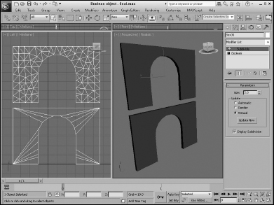
This file includes two copies of a Box object with an arch shape Boolean subtracted from it.
- Select the top object, and choose the Modifiers Radiosity Modifiers Subdivide menu command.
This applies the Subdivide modifier to the object.
- In the Parameters rollout, select the Manual update option, set the Size value to 5.0, and click Update Now.
If the Display Subdivision option is enabled, then the changes are visible in the viewport.
- Open the Advanced Lighting panel with the Rendering Radiosity menu command (or press the 9 key). Select Radiosity from the drop-down menu.
Figure 45.10 shows the two objects with and without the Subdivide modifier applied. The top object is ready for a radiosity solution.
FIGURE 45.10 Subdividing an irregular mesh prepares it for radiosity lighting.
Painting with light
The Light Painting rollout (found in the Advanced Lighting panel of the Render Scene dialog box), shown in Figure 45.11, includes buttons for Adding Illumination, Subtracting Illumination, and Picking an Illumination value from the scene. Using these tools, you can paint lighting on the objects in the scene. The Clear button removes all the changes you've made using the Light Painting tool.
FIGURE 45.11 Because lighting is saved as a light map, you can add or subtract light from the scene using a brush tool.
![]()
Rendering parameters and statistics
Settings in the Rendering Parameters rollout (shown in Figure 45.12) are used during the rendering process. The Re-Use and Render Direct Illumination options give you the chance to reuse the existing radiosity solution when rendering or to recalculate it as part of the rendering process. This can save some time during rendering.
FIGURE 45.12 The Rendering Parameters and Statistics rollouts offer rendering options and statistics for radiosity solutions.
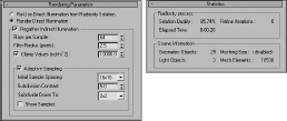
The Regather Indirect Illumination option enables a Light-Tracer-like step along with the radiosity solution and produces an image that has the best of both solutions. The regathering options are the same as those defined for the light tracer.
The Statistics rollout includes information about the radiosity process. Using this information, you can judge whether the settings are too high or too low.
Tutorial: Lighting a house interior with radiosity
Radiosity works best in indoor scenes or scenes that are mostly interior. The only light source for this scene is a Daylight system and a single Omni light in the front hallway.
To light a house interior with radiosity, follow these steps:
- Open the House interior.max file from the Chap 45 directory on the CD.
- Open the Advanced Lighting panel with the Rendering Radiosity menu command (or press the 9 key). Select Radiosity from the drop-down list in the Select Advanced Lighting rollout.
- In the Radiosity Processing Parameters rollout, set the Refine Iterations value to 2 and click the Start button to have Max compute the radiosity solution.
- In the Rendering Parameters rollout, enable the Render Direct Illumination, the Regather Indirect Illumination, and the Adaptive Sampling options. Then click the Render button to begin the rendering process.
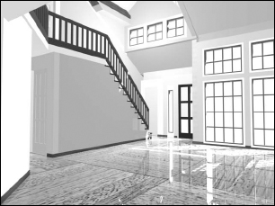
Figure 45.13 shows the finished rendered house interior. Notice that all surfaces are well lit even though the scene has a limited number of lights.
Cross-Reference
This same house interior is rendered with mental ray in Chapter 47, “Rendering with mental ray and iray.”
FIGURE 45.13 The radiosity solution for this scene adds to the lighting levels for the entire room.
Using Local and Global Advanced Lighting Settings
Just like with the Light Tracer, you can set advanced lighting settings locally for specific objects using the Object Properties dialog box, opened with the Edit ![]() Object Properties menu command. This dialog box includes an Advanced Lighting panel, and several of the settings are specific to radiosity.
Object Properties menu command. This dialog box includes an Advanced Lighting panel, and several of the settings are specific to radiosity.
For the selected objects, you can specify whether they Cast Shadows and Receive Illumination. For a radiosity solution, you also can select to enable or disable Diffuse, Specular, Exclude from Regathering, and Subdividing. The Radiosity Refine Iterations value lets you set the number of iterations for the current selection. Think of Refine Iterations as the quality setting. You can set it for all objects or just for the selected object. It works by comparing the variance between adjacent faces.
If any light objects are selected, you can select to exclude them from radiosity processing or to store the illumination values with the mesh.
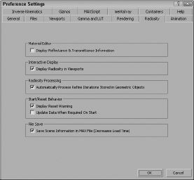
The Preference Settings dialog box also includes a Radiosity panel. Using this panel, shown in Figure 45.14, you can set the advanced lighting settings that apply to all objects globally.
In the Radiosity panel of the Preference Settings dialog box is an option to Display Reflectance & Transmittance Information. If this option is enabled, this information (average and maximum percent values) appears directly below the sample slots. You also can select to have the radiosity solution displayed in the viewports and to automatically process any refine iterations noted in the Object Properties dialog box for a given object. Radiosity processing includes a couple of warning dialog boxes that appear—one when the current solution is reset, and another to update the solution when the Start button is clicked. You can disable both of these warnings. The final option is to save the radiosity solution with the Max file. This slightly increases the file size, but it doesn't require that you recalculate the radiosity solution when the file is opened again.
FIGURE 45.14 Use the Radiosity panel of the Preference Settings dialog box to set global parameters.
Working with Advanced Lighting Materials
Applying an advanced lighting solution can have a direct impact on the materials in the scene. The Material Editor includes two materials that are useful for working with advanced lighting: Advanced Lighting Override and Lightscape materials.
Advanced Lighting Override
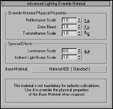
The Advanced Lighting Override material type includes material parameters that override the global Advanced Lighting solution. These parameters let you set the amount of Reflectance, Color Bleed, Transmittance, Luminance, and Bump Map Scale that the material uses. This offers a way to make a specific material have its own defined lighting parameters.
Note
The Advanced Lighting Override material does not need to be applied to all objects that are to receive advanced lighting. It is used only to override the existing scene settings for certain materials.
As an example of how this material can be used, consider the hot plate example. Rather than excluding objects from the Advanced Lighting calculations, you can instead use the Light Tracer panel to set the global settings for the scene and apply the Advanced Lighting Override material to the hot plate coils with a higher Color Bleed value. This causes the coils to bleed, but not the rest of the scene.
Another common use for this material is to use the Luminance Scale value to cause self-illuminating materials to add light energy to the global illumination calculations. In other words, increasing this value makes self-illuminating materials act as lights to the scene.
The Advanced Lighting Override material parameters, shown in Figure 45.15, let you set the amount of Reflectance, Color Bleed, Transmittance, Luminance, and Indirect Light Bump Scale that the material uses.
FIGURE 45.15 The Advanced Lighting Override Material rollout defines how light interacts with the material.
Lightscape material
The Lightscape material type lets you apply a material to objects that are imported from Lightscape. They are used to control how the radiosity is mapped to objects. The Basic Parameters rollout includes values for Brightness, Contrast, Ambient Light, and Bump Amount. You also can enable Daylight and Exterior Scene options. These values are applied in addition to the base material.
Using Lighting Analysis
To get information about the current lighting solution, you can use the Lighting Analysis Assistant. The scene must include a lighting solution before this tool is available. You can access this tool by selecting the Lighting Analysis menu command. This opens the Lighting Analysis Assistant dialog box, shown in Figure 45.16.
Note
This feature is available only in 3ds Max 2012 Design.
FIGURE 45.16 The Lighting Analysis Assistant dialog box displays the light values at the specified location.
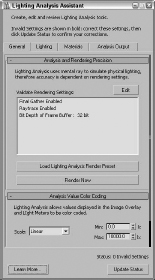
In order for the Lighting Analysis Assistant tools to work, you need to have a lighting solution for the current scene, and you need to have mental ray enabled using real-world parameters and photometric lights. If any of these conditions isn't met, it is indicated in the General panel and listed in bold. After making changes, you can press the Update Status button to recheck the settings. The General panel also includes a color spectrum that will be overlaid over the scene to show lighting values in different colors. This helps you identify places where the light isn't sufficient or where lights are too bright.
The Lighting panel shows the current lights applied to the scene and lets you edit their parameters from a single location. If any of the lights are invalid, then they will be identified in the Lighting panel. If you click the Select Invalid Light button, then any invalid lights are selected, and you can turn them on in the Modify panel.
The Lighting Analysis tools also require that all scene materials are physically correct using the mental ray architecture materials or the ProMaterials. Invalid materials are identified in the Materials panel, which can be a large number if you have a complex scene. The Materials panel includes a button to Assign Generic Valid Material to Selected Objects that can be used to quickly reassign any invalid materials.
The Analysis Output panel includes a button for creating Light Meters that can measure the light intensity at placed locations in the scene. Light Meters also can be created and placed using the Create ![]() Helpers
Helpers ![]() LightMeter menu command. When you press the Calculate All Light Meters Now button in the Lighting Analysis Assistant dialog box, the scene is rendered and the light values are displayed within the viewports. This information also can be exported to a CSV file. Light Meters can be set to measure Total Illuminance, Direct Illuminance, Indirect Illuminance, or Daylight Factor.
LightMeter menu command. When you press the Calculate All Light Meters Now button in the Lighting Analysis Assistant dialog box, the scene is rendered and the light values are displayed within the viewports. This information also can be exported to a CSV file. Light Meters can be set to measure Total Illuminance, Direct Illuminance, Indirect Illuminance, or Daylight Factor.
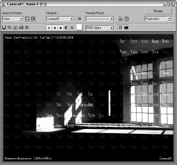
The Lighting Output panel in the Lighting Analysis Assistant dialog box includes a feature to Create Image Overlay Render Effect. This button adds a render effect to the scene that displays the lighting levels for the entire scene. When the scene is rendered, lighting values are displayed in the Rendered Frame Window, as shown in Figure 45.17.
FIGURE 45.17 The Lighting Analysis Assistant renders the scene with lighting values shown.
Summary
Advanced lighting offers a new way to shine lights on your scenes. With these features, many new lighting options are available. Advanced lighting enables two global illumination methods: light tracing and radiosity. In this chapter, you accomplished the following:
- Enabled advanced lighting
- Discovered light tracing
- Set local advanced lighting settings
- Discovered radiosity
- Used the Subdivide modifier
- Set local and global advanced lighting settings
- Used advanced lighting materials and the Lighting Analysis Assistant
The next chapter deals with fire and smoke and other Atmospheric effects. It also deals with the various Render Effects that Max can generate.