
CHAPTER 46
Using Atmospheric and Render Effects
Using Exposure Controls
Using Atmospheric Apparatus gizmos to position atmospheric effects
Using the Fire effect
Working with fog
Adding render effects
Using the Lens Effects to add glows, rays, and streaks
Understanding the other types of render effects
In the real world, an environment of some kind surrounds all objects. The environment does much to set the ambiance of the scene. For example, an animation set at night in the woods has a very different environment than one set at the horse races during the middle of the day. Max includes dialog boxes for setting the color, background images, and lighting environment; these features can help define your scene.
This chapter covers Exposure Controls, atmospheric effects, including the likes of clouds, fog, and fire. These effects can be seen only when the scene is rendered.
Max also has a class of effects that you can interactively render to the Rendered Frame window without using any post-production features, such as the Video Post dialog box. These effects are called render effects. Render effects can save you lots of time that you would normally spend rendering an image, touching it up, and repeating the process again and again.
Using Exposure Controls
The Exposure Control rollout of the Environment panel lets you control output levels and color rendering ranges. You can access the Environment panel from the Rendering ![]() Environment menu command or by pressing the 8 key. Controlling the exposure of film is a common procedure when working with film and can result in a different look for your scene. Enabling the Exposure Controls can add dynamic range to your rendered images that is more comparable to what the eyes actually see. If you've worked with a Histogram in Photoshop, then you'll understand the impact that the Exposure Controls can have. The default selection is Automatic Exposure Control.
Environment menu command or by pressing the 8 key. Controlling the exposure of film is a common procedure when working with film and can result in a different look for your scene. Enabling the Exposure Controls can add dynamic range to your rendered images that is more comparable to what the eyes actually see. If you've worked with a Histogram in Photoshop, then you'll understand the impact that the Exposure Controls can have. The default selection is Automatic Exposure Control.
The Active option lets you turn this feature on and off. The Process Background and Environment Maps option causes the exposure settings to affect the background and environment images. When this option is disabled, only the scene objects are affected by the exposure control settings. The Exposure Control rollout also includes a Render Preview button that displays the rendered scene in a tiny pane. The preview pane is small, but for most types of exposure control settings it is enough. When you click the Render Preview button, the scene is rendered. This preview is then automatically updated whenever a setting is changed.
Automatic, Linear, and Logarithmic Exposure Control
Selecting Automatic Exposure Control from the drop-down list automatically adjusts your rendered output to be closer to what your eyes can detect. Monitors are notoriously bad at reducing the dynamic range of the colors in your rendered image. This setting provides the needed adjustments to match the expanded dynamic range of your eyes.
When the Automatic Exposure Control option is selected, a new rollout appears in the Environment panel. This rollout includes settings for Brightness, Contrast, Exposure Value, and Physical Scale. You also can enable Color Correction, select a color, and select an option to Desaturate Low Levels. The Contrast and Brightness settings can range from 0 to 100. A Contrast value of 0 displays all scene objects with the same flat, gray color, and a Brightness value of 100 displays all scene objects with the same flat, white color. The Exposure Value can range from −5 to 5 and determines the amount of light allowed in the scene.
Another exposure control option is Linear Exposure Control. Although this option presents the same settings as the Automatic Exposure Control, the differences between the minimum and maximum values are a straight line across the light spectrum.
Tip
The tricky part is to know when to use which Exposure Control. For still images, the Automatic Exposure Control is your best bet, but for animations, you should use the Logarithmic Exposure Control. Automatic is also a good choice for any scenes that use many lighting effects. Using any of the exposure controls besides the Logarithmic Exposure Control when animating can lead to flickering. The Linear Exposure Control should be used for low dynamic range scenes such as nighttime or cloudy scenes.
The Logarithmic Exposure Control option replaces the Exposure Value setting with a Mid Tones setting. This setting controls the colors between the lowest and highest values. This exposure control option also includes options to Affect Indirect Only and Exterior Daylight. You should enable the Affect Indirect Only option if you use only standard lights in the scene, but if your scene includes an IES Sun light, then enable the Exterior Daylight option to tone down the intensity of the light.
Cross-Reference
You should always use the Logarithmic Exposure Control setting when enabling the advanced lighting features because it works well with low-level light. You can learn more about the advanced lighting radiosity features in Chapter 45, “Working with Advanced Lighting, Light Tracing, and Radiosity.”
Pseudo Color Exposure Control
As you work with advanced lighting solutions and with radiosity, determining whether interior spaces and objects have too much light or not enough light can be difficult, especially when comparing objects on opposite sides of the scene. This is where the Pseudo Color Exposure Control option comes in handy.
This exposure control option projects a band of colors (or grayscale) in place of the material and object colors that represent the illumination or luminance values for the scene. With these pseudo-colors, you can quickly determine where all the lighting is consistent and where it needs to be addressed.
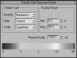
In the Pseudo Color Exposure Control rollout, shown in Figure 46.1, you can select to apply the colors to show Illumination or Luminance. You also can select to use a Colored or Grayscale style and to make the Scale Linear or Logarithmic. The Min and Max settings let you control the ranges of the colors, and a Physical Scale setting is included. The color (or grayscale) band is shown across the bottom of the rollout with the values for each color underneath.
FIGURE 46.1 The Pseudo Color Exposure Control rollout can display illumination and luminance values as colors.
When this exposure control is used, the associated render element is automatically set in the Render Elements rollout of the Render Scene dialog box. If the scene is rendered, then the appropriate (Illumination or Luminance) render element is also rendered.
Cross-Reference
See Chapter 49, “Compositing with Render Elements and the Video Post Interface,” for more on render elements.
Photographic Exposure Control
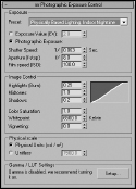
If you're comfortable working with camera settings such as Shutter Speed, Aperture, and Film Speed, then the Photographic Exposure Control puts these settings at your fingertips using real-world values. Even if you're not familiar with camera settings, you can use one of the available presets from the list at the top of the rollout, shown in Figure 46.2.
Note
The Photographic Exposure Control is available only for the mental ray render engine.
Tutorial: Using the Logarithmic Exposure Control
As you start to use the new photometric lights, you may find it difficult to get the settings just right. The results are oversaturation or undersaturation, but luckily the Logarithmic Exposure Control can quickly fix any problems that appear.
FIGURE 46.2 The Photographic Exposure Control rollout works with real-world camera settings.
To adjust the effect of a photometric light using the Logarithmic Exposure Control, follow these steps:
- Open the Array of chrome spheres.max file from the Chap 46 directory on the CD.
This file contains lots and lots of chrome mapped spheres with advanced lighting enabled.
- Choose Rendering
 Render (or press the F10 key) to open the Render Scene dialog box, and click the Render button.
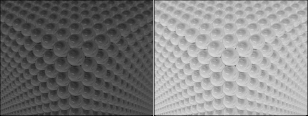
It takes a while to render, but notice the results, shown on the left in Figure 46.3.
- Choose Rendering Environment (or press the 8 key) to open the Environment & Effects dialog box. In the Exposure Control rollout, select Logarithmic Exposure Control from the drop-down list, and enable the Active and Process Background and Environment Maps options. Then click the Render Preview button.
- In the Logarithmic Exposure Control rollout, set the Brightness value to 60, set the Contrast value to 100, and enable the Desaturate Low Levels option.
- In the Render Scene dialog box, click the Render button again to see the updated rendering.
The image on the right in Figure 46.3 shows the rendered image with exposure control enabled.
FIGURE 46.3 This rendered image shows an image before and after exposure control was enabled.
Creating Atmospheric Effects
The Environment and Effects dialog box (keyboard shortcut, 8) contains rollouts for adding atmospheric effects to your scene, but the first question is where. Atmospheric effects are placed within a container called an Atmospheric Apparatus gizmo, which tells the effect where it should be located. However, only the Fire and the Volume Fog effects need Atmospheric Apparatus gizmos. To create an Atmospheric Apparatus gizmo, select Create ![]() Helpers
Helpers ![]() Atmospherics and choose the apparatus type.
Atmospherics and choose the apparatus type.
The three different Atmospheric Apparatus gizmos are BoxGizmo, SphereGizmo, and CylGizmo. Each has a different shape similar to the primitives.
Working with the Atmospheric Apparatus
Selecting a gizmo and opening the Modify panel reveal two different rollouts: one for defining the basic parameters such as the gizmo dimensions, and another labeled Atmospheres & Effects, which you can use to Add or Delete an Environment Effect to the gizmo. Each gizmo parameters rollout also includes a Seed value and a New Seed button. The Seed value sets a random number used to compute the atmospheric effect, and the New Seed button automatically generates a random seed. Two gizmos with the same seed values have nearly identical results.
Adding effects to a scene
The Add button opens the Add Atmosphere dialog box, where you can select an atmospheric effect. The selected effect is then included in a list in the Atmospheres & Effects rollout. You can delete these atmospheres by selecting them from the list and clicking the Delete button. The Setup button is active if an effect is selected in the list. It opens the Environment and Effects dialog box. Adding Atmospheric Effects in the Modify panel is purely for convenience. They can also be added using the Environment and Effects dialog box.
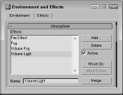
In addition to the Modify panel, you can add atmospheric effects to the scene using the Atmosphere rollout in the Environment and Effects dialog box, shown in Figure 46.4. This rollout is pretty boring until you add an effect to it. You can add an effect by clicking on the Add button. This opens the Add Atmospheric Effect dialog box, which includes by default four atmospheric effects: Fire Effect, Fog, Volume Fog, and Volume Light. With plug-ins, you can increase the number of effects in this list. The selected effect is added to the Effects list in the Atmosphere rollout.
FIGURE 46.4 The Environment and Effects dialog box lets you select atmospheric effects.
You can delete an effect from the current Effects list in the Environment and Effects dialog box by selecting the effect and clicking the Delete button. The effects are applied in the order in which they are listed, so the effects at the bottom of the list are layered on top of all other effects. To the right of the Effects pane are the Move Up and Move Down buttons, used to position the effects in the list. Below the Effects pane is a Name field where you can type a new name for any effect in this field. This enables you to use the same effect multiple times. The Merge button opens the Merge Atmospheric Effects dialog box, where you can select a separate Max file. You can then select and load any render effects from the other file.
Using the Fire Effect
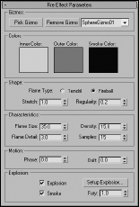
To add the Fire effect to the scene, select the Rendering ![]() Environment (8) menu command and open the Environment panel; then click the Add button and select the Fire Effect selection. This opens the Fire Effect Parameters rollout, shown in Figure 46.5. At the top of the Fire Effect Parameters rollout is the Pick Gizmo button; clicking this button lets you select a gizmo in the scene. The selected gizmo appears in the drop-down list to the right. You can select multiple gizmos. To remove a gizmo from the list, select it and click the Remove Gizmo button.
Environment (8) menu command and open the Environment panel; then click the Add button and select the Fire Effect selection. This opens the Fire Effect Parameters rollout, shown in Figure 46.5. At the top of the Fire Effect Parameters rollout is the Pick Gizmo button; clicking this button lets you select a gizmo in the scene. The selected gizmo appears in the drop-down list to the right. You can select multiple gizmos. To remove a gizmo from the list, select it and click the Remove Gizmo button.
FIGURE 46.5 The Fire Effect Parameters rollout lets you define the look of the effect.
Note
The Fire effect renders only in nonorthographic views such as Perspective or a camera view.
The three color swatches define the color of the fire effect and include an Inner Color, an Outer Color, and a Smoke Color. The Smoke Color is used only when the Explosion option is set. The default red and yellow colors make fairly realistic fire.
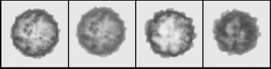
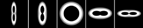
The Shape section includes two Flame Type options: Tendril and Fireball. The Tendril shape produces veins of flames, and the Fireball shape is rounder and puffier. Figure 46.6 shows four fire effects. The left two have the Tendril shape, and the two on the right are set to Fireball. The difference is in the Density and Flame Detail settings.
FIGURE 46.6 The Fire atmospheric effect can be either Tendril or Fireball shaped.
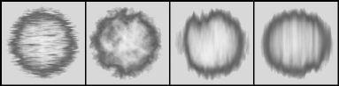
The Stretch value elongates the individual flames along the gizmo's Z-axis. Figure 46.7 shows the results of using the Stretch value. The Stretch values for these gizmos, from left to right, are 0.1, 1.0, 5.0, and 50.
FIGURE 46.7 The Stretch value can elongate flames.
The Regularity value determines how much of the Atmospheric Apparatus is filled. The spherical gizmos in the previous figures were all set to 0.2, so the entire sphere shape wasn't filled. A setting of 1.0 adds a spherical look to the Fire effect because the entire gizmo is filled. For a more random shape, use a small Regularity value.
The Flame Size value affects the overall size of each individual flame (though this is dependent on the gizmo size as well). The Flame Detail value controls the edge sharpness of each flame and can range from 1 to 10. Lower values produce fuzzy, smooth flames, but higher values result in sharper, more distinct flames.
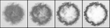
The Density value determines the thickness of each flame in its center; higher Density values result in flames that are brighter at the center, while lower values produce thinner, wispy flames. Figure 46.8 shows the difference caused by Density values of, from left to right, 10, 20, 50, and 100.
FIGURE 46.8 The Fire effect brightness is tied closely to the flame's Density value.
The Samples value sets the rate at which the effect is sampled. Higher sample values are required for more detail, but they increase the render time.
The Motion section includes options for setting the Phase and Drift of a fire effect. The Phase value determines how wildly the fire burns. For a wild, out-of-control fire, animate the Phase value to change rapidly. For a constant, steady fire, keep the value constant throughout the frames. The Drift value sets the height of the flames. High Drift values produce high, hot-burning flames.
When the Explosion check box is selected, the fire is set to explode. The Start and End Times for the explosion are set in the Setup Explosion Phase Curve dialog box that opens when the Setup Explosion button is clicked. If the Smoke option is checked, then the fire colors change to the smoke color for Phase values between 100 and 200. The Fury value varies the churning of the flames. Values greater than 1.0 cause faster churning, and values lower than 1.0 cause slower churning.
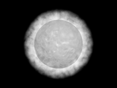
Tutorial: Creating the sun
You can use the Fire effect to create a realistic sun. The modeling part is easy—all it requires is a simple sphere—but the real effects come from the materials and the Fire effect.
To create a sun, follow these steps:
- Open the Sun.max file from the Chap 46 directory on the CD.
This file contains a simple sphere with a bright yellow material applied to it.
- Select Create Helpers Atmospherics Sphere Gizmo, and drag a sphere in the Front viewport that encompasses the “sun” sphere.
- With the SphereGizmo still selected, open the Modify panel and click the Add button in the Atmospheres & Effects rollout or you can use the Add button located in the Atmosphere rollout in the Environment and Effects dialog box, which is opened using the Rendering Environment menu command or by pressing the 8 key. Select Fire Effect from the Add Atmosphere dialog box, and click OK. Then select the Fire effect, and click the Setup button.
The Environment and Effects dialog box opens.
- In the Fire Effects Parameters rollout, leave the default colors as they are—Inner Color yellow, Outer Color red, and Smoke Color black. For the Flame Type, select Tendril with Stretch and Regularity values of 1. Set the Flame Size to 30, the Density to 15, the Flame Detail to 10, and the Samples to 15.
Figure 46.9 shows the resulting sun after it's been rendered.
FIGURE 46.9 A sun image created with a simple sphere, a material with a Noise Bump map, and the Fire effect
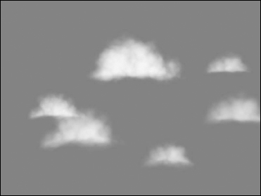
Tutorial: Creating clouds
Sky images are fairly easy to find, or you can just take your camera outside and capture your own. The trick comes when you are trying to weave an object in and out of clouds. Although you can do this with a Shadow/Matte mask, it would be easier if the clouds were actual 3D objects. In this tutorial, you'll create some simple clouds using the Fire effect.
To create some clouds for a sky backdrop, follow these steps:
- Open the Clouds.max file from the Chap 46 directory on the CD.
This file includes several hemispherical-shaped Atmospheric Apparatus gizmos.
- Choose Rendering Environment (or press the 8 key) to open the Environment and Effects dialog box. Click the Background Color swatch, and select a light blue color. In the Atmosphere section, click the Add button, select Fire Effect from the Add Atmospheric Effect list, and click OK.
- Name the effect Clouds, click the Pick Gizmo button, select each of the Sphere Gizmo objects in the viewports, and then click on each of the color swatches. Change the Inner Color to a dark gray, the Outer Color to a light gray, and the Smoke Color to white. Set the Shape to Fireball with a Stretch of 1 and a Regularity of 0.2. Set the Flame Size to 35, the Flame Detail to 3, the Density to 15, and the Samples to 15.
- In the Fire Effect Parameters rollout, click the Pick Gizmo button and then click one of the gizmos in the viewports. Repeat this step until you've selected all the gizmos.
Figure 46.10 shows the resulting sky backdrop. By altering the Fire parameters, you can create different types of clouds.
FIGURE 46.10 You can use the Fire atmospheric effect to create clouds.
Using the Fog Effect
Fog is an atmospheric effect that obscures objects or backgrounds by introducing a hazy layer; objects farther from view are less visible. The normal Fog effect is used without an Atmospheric Apparatus gizmo and appears between the camera's environment range values. The camera's Near and Far Range settings set these values.
In the Environment and Effects dialog box, the Fog Parameters rollout appears when the Fog effect is added to the Effects list. This rollout, shown in Figure 46.11, includes a color swatch for setting the fog color. It also includes an Environment Color Map button for loading a map. If a map is selected, the Use Map option turns it on or off. You can also select a map for the Environment Opacity, which affects the fog density.
The Fog Background option applies fog to the background image. The Type options include Standard and Layered fog. Selecting one of these fog background options enables its corresponding parameters.
FIGURE 46.11 The Fog Parameters rollout lets you use either Standard fog or Layered fog.
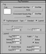
The Standard parameters include an Exponential option for increasing density as a function of distance. If this option is disabled, the density is linear with distance. The Near and Far values are used to set the range densities.
Layered fog simulates layers of fog that move from dense areas to light areas. The Top and Bottom values set the limits of the fog, and the Density value sets its thickness. The Falloff option lets you set where the fog density goes to 0. The Horizon Noise option adds noise to the layer of fog at the horizon as determined by the Size, Angle, and Phase values.
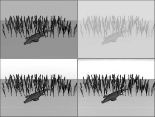
Figure 46.12 shows several different fog options. The upper-left image shows the scene with no fog, the upper-right image uses the Standard option, and the lower-left image uses the Layered option with a Density of 50. The lower-right image has the Horizon Noise option enabled.
Using the Volume Fog effect
You can add the Volume Fog effect to a scene by clicking the Add button and selecting the Volume Fog selection. This effect is different from the Fog effect in that it gives you more control over the exact position of the fog. This position is set by an Atmospheric Apparatus gizmo. The Volume Fog Parameters rollout, shown in Figure 46.13, lets you select a gizmo to use with the Pick Gizmo button. The selected gizmo is included in the drop-down list to the right of the buttons. Multiple gizmos can be selected. The Remove Gizmo button removes the selected gizmo from the list.
FIGURE 46.12 A rendered image with several different Fog effect options applied
Note
The Atmospheric Apparatus gizmo contains only a portion of the total Volume Fog effect. If the gizmo is moved or scaled it displays a different cropped portion of fog.
FIGURE 46.13 The Volume Fog Parameters rollout includes parameters for controlling the fog density and type.
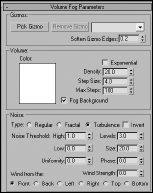
The Soften Gizmo Edges value feathers the fog effect at each edge. This value can range from 0 to 1.
Many of the settings for Volume Fog are the same as those for the Fog effect, but Volume Fog has several settings that are unique to it. These settings help set the patchy nature of Volume Fog. Step Size determines how small the patches of fog are. The Max Steps value limits the sampling of these small steps to keep the render time in check.
The Noise section settings also help determine the randomness of Volume Fog. Noise types include Regular, Fractal, Turbulence, and Invert. The Noise Threshold limits the effect of noise. Wind settings include direction and strength. The Phase value determines how the fog moves.
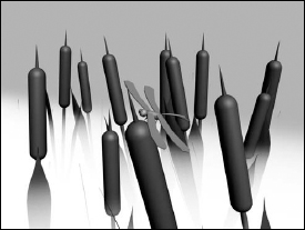
Tutorial: Creating a swamp scene
When I think of fog, I think of swamps. In this tutorial, you model a swamp scene. To use the Volume Fog effect to create the scene, follow these steps:
- Open the Dragonfly in a foggy swamp.max file from the Chap 46 directory on the CD.
This file includes several cattail plants and a dragonfly positioned on top of one of the cattails.
- Select Create Helpers Atmospherics Box Gizmo, and drag a box that covers the lower half of the cattails in the Top viewport.
- Choose Rendering Environment (or press the 8 key) to open the Environment and Effects dialog box. Click the Add button to open the Add Atmospheric Effect dialog box, and then select Volume Fog. Click OK. In the Volume Fog Parameters rollout, click the Pick Gizmo button and select the BoxGizmo in a viewport.
- Set the Density to 0.5, enable the Exponential option and select the Noise Type Turbulence. Then set the Uniformity to 1.0 and the Wind Strength to 10 from the Left.
Figure 46.14 shows the finished image. Using Atmospheric Apparatus gizmos, you can position the fog in the exact place where you want it.
FIGURE 46.14 A rendered image that uses the Volume Fog effect
Using the Volume Light effect
The final choice in the Environment and Effects dialog box is the Volume Light effect. This effect shares many of the same parameters as the other atmospheric effects. Although this is one of the atmospheric effects, it deals with lights and fits better in that section.
Cross-Reference
To learn about the Volume Light atmospheric effect, see Chapter 20, “Using Lights and Basic Lighting Techniques.”
Adding Render Effects
In many cases, rendering a scene is only the start of the work to produce some final output. The post-production process is often used to add lots of different effects, as you'll see when I discuss the Video Post interface. But just because you can add it in post-production doesn't mean you have to add it in post-production. Render effects let you apply certain effects as part of the rendering process.
You can set up all render effects from the Rendering Effects panel, which you open by choosing Rendering ![]() Effects. Figure 46.15 shows this dialog box.
Effects. Figure 46.15 shows this dialog box.
FIGURE 46.15 The Effects panel lets you apply interactive post-production effects to an image.
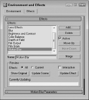
The Effects pane displays all the effects that are included in the current scene. To add a new effect, click the Add button to open the Add Effect dialog box, in which you can select from a default list of nine effects: Hair and Fur, Lens Effects, Blur, Brightness and Contrast, Color Balance, Depth of Field, File Output, Film Grain, and Motion Blur. You can delete an effect from the current list by selecting that effect and clicking the Delete button.
Below the Effects pane is a Name field. You can type a new name for any effect in this field; doing so enables you to use the same effect multiple times. The effects are applied in the order in which they are listed in the Effects pane. To the right of the Effects pane are the Move Up and Move Down buttons, which you use to reposition the effects in the list. The effects are added to the scene in the order that they are listed.
Caution
It is possible for one effect to cover another effect. Rearranging the order can help resolve this problem.
The Merge button opens the Merge Effect dialog box, where you can select a separate Max file. If you select a Max file and click Open, the Merge Rendering Effects dialog box presents you with a list of render effects used in the opened Max file. You can then select and load any of these render effects into the current scene.
The Preview section holds the controls for interactively viewing the various effects. Previews are displayed in the Rendered Frame Window and can be set to view All the effects or only the Current one. The Show Original button displays the scene before any effects are applied, and the Update Scene button updates the rendered image if any changes have been made to the scene.
Note
If the Rendered Frame Window isn't open, any of these buttons opens it and renders the scene with the current settings in the Render Scene dialog box.
The Interactive option automatically updates the image whenever an effect parameter or scene object is changed. If this option is disabled, you can use the Update Effect button to manually update the image.
Caution
If the Interactive option is enabled and the Rendering Effects panel is open, the image is re-rendered in the Rendered Frame Window every time a change is made to the scene. This can slow down the system dramatically.
The Currently Updating bar shows the progress of the rendering update.
The remainder of the Rendering Effects panel contains global parameters and rollouts for the selected render effect. These rollouts are covered in this chapter, along with their corresponding effects.
Cross-Reference
The Hair and Fur render effect offers the ability to add hair and fur to models. The Hair and Fur features—including the render effect—are covered in Chapter 29, “Adding and Styling Hair and Fur, and Using Cloth.”
Creating Lens Effects
Of the eight available render effects, the first one on the list will be used perhaps more often than all the others combined. The Lens Effects option includes several different effects itself, ranging from glows and rings to streaks and stars.
Lens Effects simulate the types of lighting effects that are possible with actual camera lenses and filters. When the Lens Effects selection is added to the Effects list and selected, several different effects become available in the Lens Effects Parameters rollout, including Glow, Ring, Ray, Auto Secondary, Manual Secondary, Star, and Streak. When one of these effects is included in a scene, rollouts and parameters for that effect are added to the panel as well.
Several of these Lens Effects can be used simultaneously. To include an effect, open the Environment and Effects dialog box with the Rendering ![]() Effects menu command, click the Add button, and select Lens Effect from the available effects. Then go to the Lens Effects Parameters rollout, select the desired effect from the list on the left, and click the arrow button pointing to the right. The pane on the right lists the included effects. Use the left-pointing arrow button to remove effects from the list.
Effects menu command, click the Add button, and select Lens Effect from the available effects. Then go to the Lens Effects Parameters rollout, select the desired effect from the list on the left, and click the arrow button pointing to the right. The pane on the right lists the included effects. Use the left-pointing arrow button to remove effects from the list.
Global Lens Effects Parameters
Under the Lens Effects Parameters rollout in the Rendering Effects panel is the Lens Effects Globals rollout. All effects available in Lens Effects use the two common tabbed panels in this rollout: Parameters and Scene. These two tabbed panels are shown side by side in Figure 46.16.
FIGURE 46.16 The Parameters tabbed panel of the Lens Effects Globals rollout lets you load and save parameter settings. The Scene tabbed panel lets you set the effect's Size and Intensity.

The Global Parameters tabbed panel
The Parameters panel of the Lens Effects Globals rollout includes Load and Save buttons for loading and saving parameter settings specified in the various rollouts. These settings are saved as LZV files.
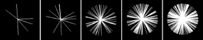
The Size value determines the overall size of the effect as a percentage of the rendered image. Figure 46.17 shows the center of the Star Lens Effects with an Intensity value of 500 and Size values of 5, 10, 20, 50, and 100. The Size value increases the entire effect diameter and also the width of each radial line.
FIGURE 46.17 These Star Lens Effects vary in size.

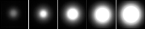
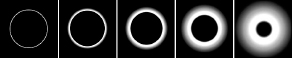
The Intensity value controls the brightness and opacity of the effect. Large values are brighter and more opaque, and small values are dimmer and more transparent. The Size and Intensity values can be locked together. Intensity and Size values can range from 0 to 500. Figure 46.18 shows a glow effect with Intensity values of (from left to right) 50, 100, 200, 350, and 500.
FIGURE 46.18 Lens Effects also can vary in intensity, like these glows.
The Seed value provides the randomness of the effect. Changing the Seed value changes the effect's look. The Angle value spins the effect about the camera's axis. The Squeeze value lengthens the horizontal axis for positive values and lengthens the vertical axis for negative values. Squeeze values can range from −100 to 100. Figure 46.19 shows a Ring effect with Squeeze values of (from left to right) −30, −15, 0, 10, and 20.
FIGURE 46.19 These Ring effects vary in Stretch values.
All effects are applied to light sources, and the Pick Light button lets you select a light in the viewport to apply the effect to. Each selected light is displayed in a drop-down list. You can remove any of these lights with the Remove Light button.
The Global Scene tabbed panel
The second Lens Effects Globals tabbed panel common to all effects is the Scene panel. This rollout includes an Affect Alpha option that lets the effect work with the image's alpha channel. The alpha channel holds the transparency information for the rendered objects and for effects if this option is enabled. If you plan on using the effect in a composite image, then enable this option.
Tip
Click the Display Alpha Channel button in the Rendered Frame Window to view the alpha channel.
The Affect Z Buffer option stores the effect information in the Z Buffer, which is used to determine the depth of objects from the camera's viewpoint.
The Distance Affects option alters the effect's Size and/or Intensity based on its distance from the camera. The Off-Center Affects option is similar, except that it affects the effect's size and intensity based on its Off-Center distance. The Direction Affects options can affect the size and intensity of an effect based on the direction in which a spotlight is pointing.
The Occlusion settings can be used to cause an effect to be hidden by an object that lies between the effect and the camera. The Inner Radius value defines the area that an object must block in order to hide the effect. The Outer Radius value defines where the effect begins to be occluded. You can also set the Size and Intensity options for the effect. The Affected by Atmospheres option allows effects to be occluded by atmospheric effects.
Glow
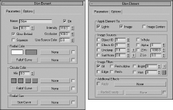
The Glow Element rollout, shown in Figure 46.20, includes parameters for controlling the look of the Glow Lens Effect. This rollout has two tabbed panels: Parameters and Options.
FIGURE 46.20 The Glow Element rollout lets you set the parameters for the Glow effect.
The Glow Element Parameters tabbed panel
In the Parameters tabbed panel of the Glow Element rollout, there is a Name field. Several glow effects can be added to a scene, and each one can have a different name. The On option turns each glow on and off.
The Parameters panel also includes Size and Intensity values. These work with the Global settings to determine the size of the glow and can be set to any positive value. The Occlusion and Use Source Color values are percentages. The Occlusion value determines how much of the occlusion set in the Scene panel of the Lens Effects Globals rollout is to be used. If the Use Source Color is at 100 percent, then the glow color is determined by the light color; if it is set to any value below 100, then the colors specified in the Source and Circular Color sections are combined with the light's color.
This panel also includes Glow Behind and Squeeze options. Glow Behind makes the glow effect visible behind objects. Squeeze enables any squeeze settings specified in the Parameters panel.
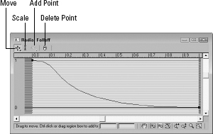
If the Use Source Color value is set to 0 percent, only the Radial Color swatches determine the glow colors. Radial colors proceed from the center of the glow circle to the outer edge. The first swatch is the inner color, and the second is the outer color. The Falloff Curve button opens the Radial Falloff function curve dialog box, shown in Figure 46.21, where you can use a curve to set how quickly or slowly the colors change.
FIGURE 46.21 The Radial Falloff dialog box lets you control how the inner radial color changes to the outer radial color.
The Circular Color swatches specify the glow color around the glow circle starting from the top point and proceeding clockwise. The Mix value is the percentage to mix the Circular colors with the Radial Colors; a value of 0 displays only the Radial colors, and a value of 100 displays only the Circular colors. You can also access the Falloff Curve dialog box for the Circular Color Falloff curve.
You can also control the Radial Size using a curve by clicking the Size Curve button. Clicking the Size Curve button accesses the Radial Size dialog box. Figure 46.22 shows several glow effects where the radial size curve has been altered. The curves are, from left to right, roughly a descending linear curve, a v-shaped curve, a wide u-shaped curve, an m-shaped curve, and a sine curve.
FIGURE 46.22 These glow effects are distorted using the Radial Size function curves.

All these colors and function curves have map buttons (initially labeled None) that enable you to load maps. Useful maps to use include Falloff, Gradient and Gradient Ramp, Noise, and Swirl. You can enable a map by using the check box to its immediate right.
The Glow Element Options tabbed panel
The Options panel of the Glow Element rollout defines where to apply the glow effect. In the Apply Element To section, the first option is to apply a glow to the Lights. These lights are selected in the Lights section of the Lens Effects Globals rollout using the Pick Light button. The other two options—Image and Image Centers—apply glows using settings contained in the Options panel.
In the Image Sources section, you can apply glows to specific objects using the Object ID option and settings. Object IDs are set for objects in the Object Properties dialog box. If the corresponding Object ID is selected and enabled in the Options panel, the object is endowed with the Glow Lens Effect.
The Effects ID option and settings work in a manner similar to Object IDs, except that they are assigned to materials in the Material Editor. You can use Effects IDs to make a subobject selection glow.
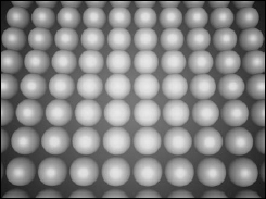
The Unclamp option and settings enable colors to be brighter than pure white. Pure White is a value of 1. The Unclamp value is the lowest value that glows. The Surf Norm (Surface Normal) option and value let you set object areas to glow based on the angle between the surface normal and the camera. The “I” button to the right inverts the value.
Figure 46.23 shows an array of spheres with the Surf Norm glow enabled. Because the glows multiply, a value of only 2 was applied. Notice that the spheres in the center have a stronger glow.
FIGURE 46.23 The Surf Norm option causes objects to glow, based on the angle between their surface normals and the camera.
In the Image Sources section, options enable these glows to be applied to the Whole scene, the Alpha channel, or the Z buffer with specified Hi and Lo values.
The Image Filters section can further refine which objects to apply the glow effect to. Options include All, Edge, Perim (Perimeter) Alpha, Perim, Brightness, and Hue. The All option applies the effect to all pixels that are part of the source. The Edge, Perim Alpha, and Perim options apply the effect only to the edges, perimeter of the alpha channel, or perimeter of the source. The Brightness option includes a value and an “I” invert button. This applies the effect only to areas with a brightness greater than the specified value. The Hue option also includes a value and a color swatch for setting the hue, which receives the effect.
The Additional Effects section lets you apply a map to the Glow Lens Effect with an Apply option and a map button. You can also control the Radial Density function curve or add a map for the Radial Density.
Tutorial: Creating shocking electricity from a plug outlet
In addition to the light objects, lighting in a scene can be provided by self-illuminating an object and using a Glow render effect. Self-illuminating an object is accomplished by applying a material with a Self-Illumination value greater than 0 or a color other than black. You can create glows by using the Render Effects dialog box or the Video Post dialog box.
Cross-Reference
For more information on applying glows using the Video Post interface, see Chapter 49, “Compositing with Render Elements and the Video Post Interface.”
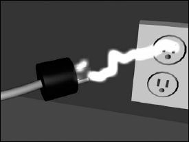
Working with a faulty electrical outlet can be a shocking experience. In this tutorial, you create an electric arc that runs from an outlet to a plug. To create the effect of electricity, you can use a renderable spline with several vertices and apply the Noise modifier to make it dance around. You can set the light by using a self-illuminating material and a Glow render effect.
To create an electric arc that runs between an outlet and a plug, follow these steps:
- Open the Electricity.max file from the Chap 46 directory on the CD.
This file includes an outlet and an electric plug. A spline runs between the outline and the plug with a Noise modifier applied to it, which will be our electric arc.
- Open the Material Editor by pressing the M key, and select the first sample slot. Select a yellow Diffuse color and an equally bright yellow for the Self-Illumination color. Set the Material Effects Channel to 1 by clicking the Material Effects ID button and holding it down until a pop-up array of numbers appears, and then drag to the number 1 and release the mouse. Drag this new material to the electric arc and close the Material Editor.
- Open the Render Effects dialog box by choosing Rendering Effects. Click the Add button, select the Lens Effects option, and click OK. Then select Lens Effects from the list, and double-click Glow in the Lens Effects Parameters rollout. Select Glow from the list; in the Glow Element rollout, set the Size to 1 and the Intensity value to 50. Then open the Options panel, set the Material ID to 1, and enable it.
Figure 46.24 shows the resulting electric arc.
FIGURE 46.24 You can create electricity using a simple spline, the Noise modifier, and the Glow render effect.
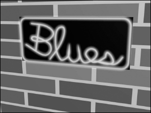
Tutorial: Creating neon
You can also use the Glow render effect to create neon signs. The letters for these signs can be simple renderable splines, as this tutorial shows.
To create a neon sign, follow these steps:
- Open the Blues neon.max file from the Chap 46 directory on the CD.
This file includes a simple sign that reads “Blues.”
- Open the Material Editor with the M key, select the first sample slot, and name it Blue Neon. Set its Diffuse color to blue and its Self-Illumination color to dark blue. Set the Material Effects Channel to 1, and apply the material to the sign.
- Open the Rendering Effects panel, and click the Add button. Double-click the Lens Effects option to add it to the Effects list. In the Lens Effects rollout, double-click the Glow option and select it in the list to enable its rollouts. In the Lens Effects Globals rollout, set the Size and Intensity values to 1. In the Glow Element rollout, set the Size to 10 and the Intensity to 100, and make sure that the Glow Behind option is selected. For the neon color, set the Use Source Color to 100. Finally, open the Options panel, set the Material ID to 1, and enable it.
Note
As an alternative to using the source color, you could set the Use Source Color value to 0 and set the Radial Color swatch to blue. This gives you more control over the glow color.
Figure 46.25 shows the rendered neon effect.
FIGURE 46.25 The glow of neon lights, easily created with render effects
Ring
The Ring Lens Effect is also circular and includes all the same controls and settings as the Glow Lens Effect. The only additional values are the Plane and Thickness values. The Plane value positions the Ring center relative to the center of the screen, and the Thickness value determines the width of the Ring's band.
Figure 46.26 shows several Ring effects with various Thickness values (from left to right): 1, 3, 6, 12, and 24.
FIGURE 46.26 Ring effects can vary in thickness.
Ray
The Ray Lens Effect emits bright, semitransparent rays in all directions from the source. It also uses the same settings as the Glow effect, except for the Num (Number) and Sharp values. The Num value is the number of rays, and the Sharp value can range from 0 to 10 and determines how blurry the rays are.
Figure 46.27 shows the Ray effect applied to a simple Omni light with increasing Num values: 6, 12, 50, 100, and 200. Notice that the rays aren't symmetrical and are randomly placed.
FIGURE 46.27 The Ray effect extends a given number of rays out from the effect center.
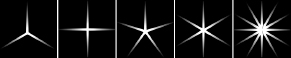
Star
The Star Lens Effect radiates semitransparent bands of light at regular intervals from the center of the effect. It uses the same controls as the Glow effect, with the addition of Width, Taper, Qty (Quantity), and Sharp values. The Width sets the width of each band. The Taper value determines how quickly the width angles to a point. The Qty value is the number of bands, and the Sharp value determines how blurry the bands are.
Figure 46.28 shows several Star effects with (from left to right) 3, 4, 5, 6, and 12 bands.
FIGURE 46.28 The Star effect lets you set the number of bands emitting from the center.
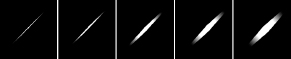
Streak
The Streak Lens Effect adds a horizontal band through the center of the selected object. It is similar to the Star effect, except it has only two bands that extend in opposite directions.
Figure 46.29 shows several Streak effects angled at 45 degrees with Width values of (from left to right) 2, 4, 10, 15, and 20.
FIGURE 46.29 The Streak effect enables you to create horizontal bands.
Auto Secondary
When a camera is moved past a bright light, several small circles appear lined up in a row proceeding from the center of the light. These secondary lens flares are caused by light refracting off the lens. You can simulate this effect by using the Auto Secondary Lens Effect.
Many of the settings in the Auto Secondary Element rollout are the same as in the Glow effect rollout described previously, but the Auto Secondary Element rollout has several unique values. Figure 46.30 shows this rollout.
The Min and Max values define the minimum and maximum size of the flares. The Axis is the length of the axis along which the flares are positioned. Larger values spread the flares out more than smaller values. The actual angle of the flares depends on the angle between the camera and the effect object.
The Quantity value is the number of flares to include. The Sides drop-down list lets you select a Circular flare or flares with three to eight sides. Below the Sides drop-down list are several preset options in another drop-down list. These include options such as Brown Ring, Blue Circle, and Green Rainbow, among others.
You can also use four Radial Colors to define the flares. The color swatches from left to right define the colors from the inside out. The spinners below each color swatch indicate where the color should end.
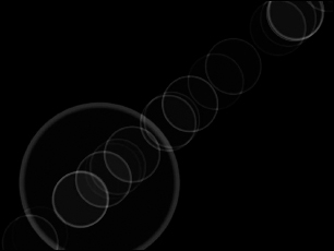
Figure 46.31 shows the Auto Secondary Effect with the Rainbow preset and the Intensity increased to 50.
FIGURE 46.30 The Auto Secondary Element rollout sets the parameters for this effect.
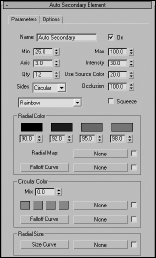
FIGURE 46.31 The Auto Secondary Effect displays several flares extending at an angle from the center of the effect.

Manual Secondary
In addition to the Auto Secondary Lens Effect, you can add a Manual Secondary Lens Effect to add some more flares with a different size and look. This effect includes a Plane value that places the flare in front of (positive value) or behind (negative value) the flare source.
Figure 46.32 shows the same flares from the previous figure with an additional Manual Secondary Effect added.
FIGURE 46.32 The Manual Secondary Effect can add some randomness to a flare lineup.
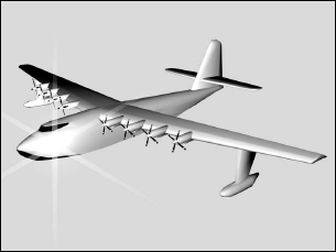
Tutorial: Making an airplane sparkle
When shiny metal planes fly through the sky, they often give off sparkling light effects. Adding some Lens Effects to an airplane scene can simulate this effect.
To make an object bright and shiny using Lens Effects, follow these steps:
- Open the Spruce Goose.max file from the Chap 46 directory on the CD.
This file includes an airplane model of the famous Spruce Goose created by Viewpoint Datalabs.
- Open the Create panel, and click the Lights category button. Create several Omni lights, and position them around the scene to provide adequate lighting. Position a single light close to the plane's surface where you want the highlight to be located—make it near the surface, and set the Multiplier value to 0.5.
- Open the Rendering Effects panel by choosing Rendering Effects (or press the 8 key). Click the Add button, and select Lens Effects. Then, in the Lens Effects Parameters rollout, select the Glow effect in the left pane and click the button pointing to the right pane.
- In the Parameters panel, click the Pick Light button and select the light close to the surface. Set the Size around 30 and the Intensity at 100. Go to the Glow Element rollout, and in the Parameters panel, set the Use Source Color to 0. Then, in the Radial Color section, click the second Radial Color swatch, and in the Color Selector dialog box, select a color like yellow and click the Close button.
- Back in the Lens Effects Parameters rollout, select Star, and add it to the list of effects. It automatically uses the same light specified for the Glow effect. In the Star Element rollout, set the Quantity (Qty) value to 6, the Size to 200, and the Intensity to 100.
Figure 46.33 shows the resulting airplane with a nice shine.
FIGURE 46.33 The Spruce Goose has had a sparkle added to it using the Glow and Star Lens Effects.
Using Other Render Effects
Now that I've covered the big brother of the render effects, let's return to the Add Effect dialog box, where six other render effects are available. If these selections aren't enough, Max also enables you to add even more options to this list via plug-ins.
Blur render effect
The Blur render effect displays three different blurring methods in the Blur Type panel: Uniform, Directional, and Radial. You can find these options in the Blur Type tabbed panel in the Blur Parameters rollout, shown in Figure 46.34.
FIGURE 46.34 The Blur Parameters rollout lets you select a Uniform, Directional, or Radial blur type.
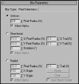
The Uniform blur method applies the blur evenly across the whole image. The Pixel Radius value defines the amount of the blur. The Directional blur method can be used to blur the image along a certain direction. The U Pixel Radius and U Trail values define the blur in the horizontal direction, and the V Pixel Radius and V Trail values blur in a vertical direction. The Rotation value rotates the axis of the blur.
The Radial blur method creates concentric blurred rings determined by the Radius and Trail values. When the Use Object Center option is selected, the None and Clear buttons become active. Clicking the None button lets you select an object about which you want to center the radial blur. The Clear button clears this selection.
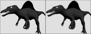
Figure 46.35 shows a dinosaur model created by Viewpoint Datalabs. The actual rendered image shows the sharp edges of the polygons. The Blur effect can help this by softening all the hard edges. The left image is the original dinosaur, and the right image has a Directional blur applied.
FIGURE 46.35 The Blur effect can soften an otherwise hard model.
The Blur Parameters rollout also includes a Pixel Selections tabbed panel, shown in Figure 46.36, that contains parameters for specifying which parts of the image get blurred. Options include the Whole Image, Non-Background, Luminance, Map Mask, Object ID, and Material ID.
FIGURE 46.36 The Pixel Selections tabbed panel (shown in two parts) of the Blur Parameters rollout lets you select the parts of the image that get the Blur effect.
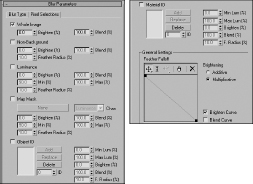
You can use the Feather Falloff curve at the bottom of the Blur Parameters rollout to define the Brighten and Blend curves. The buttons above this curve are for adding points, scaling the points, and moving them within the curve interface.
Brightness and Contrast render effect
The Brightness and Contrast render effect can alter these amounts in the image. The Brightness and Contrast Parameters rollout is a simple rollout with values for both the brightness and contrast that can range from 0 to 1. It also contains an Ignore Background option.
Color Balance render effect
The Color Balance effect enables you to tint the image using separate Cyan/Red, Magenta/Green, and Yellow/Blue channels. To change the color balance, drag the sliders in the Color Balance Parameters rollout. Other options include Preserve Luminosity and Ignore Background. The Preserve Luminosity option tints the image while maintaining the luminosity of the image, and the Ignore Background option tints the rendered objects but not the background image.
File Output render effect
The File Output render effect enables you to save the rendered file to a File or to a Device at any point during the render effect's post-processing. Figure 46.37 shows the File Output Parameters rollout.
FIGURE 46.37 The File Output Parameters rollout lets you save a rendered image before a render effect is applied.
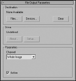
Using the Channel drop-down list in the Parameters section, you can save out Whole Images, as well as grayscale Luminance, Depth, and Alpha images.
Film Grain render effect
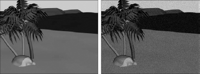
The Film Grain effect gives an image a grained look, which hardens the overall look of the image. You can also use this effect to match rendered objects to the grain of the background image. This helps the objects blend into the scene better. Figure 46.38 shows the effect.
The Grain value can range from 0 to 1. The Ignore Background option applies the grain effect only to the objects in the scene and not to the background.
FIGURE 46.38 The Film Grain render effect applies a noise filter to the rendered image.
Motion Blur render effect
The Motion Blur effect applies a simple image motion blur to the rendered output. The Motion Blur Parameters rollout includes settings for working with Transparency and a value for the Duration of the blur. Objects that move rapidly within the scene are blurred.
Depth of Field render effect
The Depth of Field effect enhances the sense of depth by blurring objects close to or far from the camera. The Pick Cam button in the Depth of Field Parameters rollout, shown in Figure 46.39, lets you select a camera in the viewport to use for this effect. Multiple cameras can be selected, and all selected cameras are displayed in the drop-down list. A Remove button lets you remove cameras.
FIGURE 46.39 The Depth of Field Parameters rollout lets you select a camera or a Focal Point to apply the effect to.
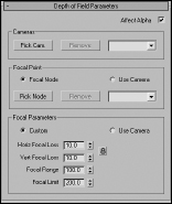
In the Focal Point section, the Pick Node button lets you select an object to use as the focal point. This object is where the camera focuses. Objects far from this object are blurred. These nodes are also listed in a drop-down list. You can remove objects from the list by selecting them and clicking the Remove button. The Use Camera option uses the camera's own settings to determine the focal point.
In the Focal Parameters section, if you select the Custom option, then you can specify values for the Horizontal and Vertical Focal Loss, the Focal Range, and the Focal Limit. The Loss values indicate how much blur occurs. The Focal Range is where the image starts to blur, and the Focal Limit is where the image stops blurring.
Figure 46.40 shows a beach scene created by Viewpoint Datalabs. For this figure, I applied the Depth of Field effect using the Pick Node button and selecting some leaves on the tree. Then I set the Focal Range to 100, the Focal Limit to 200, and the Focal Loss values to 10 for both the Horizontal and Vertical.
Cross-Reference
The Depth of Field and Motion Blur effects can also be applied using a Multi-Pass camera, as discussed in Chapter 19, “Configuring and Aiming Cameras.”
FIGURE 46.40 The Depth of Field effect focuses a camera on an object in the middle and blurs objects closer or farther away.

Summary
Creating the right environment can add lots of realism to any rendered scene. Using the Environment and Effects dialog box, you can work with atmospheric effects. Atmospheric effects include Fire, Fog, Volume Fog, and Volume Light.
Render effects are useful because they enable you to create effects and update them interactively. This gives a level of control that was previously unavailable. This chapter explained how to use render elements and render effects and described the various types.
This chapter covered these topics:
- Creating Atmospheric Apparatus gizmos for positioning atmospheric effects
- Working with the Fire atmospheric effects
- Creating fog and volume fog effects
- Applying render effects
- Using the Lens Effects to create glows, rays, and stars
- Working with the remaining render effects to control brightness and contrast, film grain, blurs, and more
- Learning how exposure controls can work
The next chapter delves into the amazing mental ray rendering engine.