
BONUS CHAPTER 4
Modeling with Patches
Apatch is a modeling type that uses curves to define the perimeter of the shape. Patches are essentially polygon surfaces stretched along a closed spline. Modifying the spline alters the surface of the patch.
In many ways, patches have advantages over the more common mesh objects. They take less memory to store, are easier to edit at the edges, and are easy to join to one another.
Introducing Patch Grids
Because patches have splines along their edges, a patch can be deformed in ways that a normal polygon cannot. For example, a polygon always needs to be coplanar, meaning that if you look at it on edge, it appears as a line. A patch doesn't have this requirement and can actually bend, which permits greater control over the surface and makes it better for modeling things like clothes and natural objects like leaves.
Note
Patches have many similarities to the NURBS modeling type. NURBS stands for Non-Uniform Rational B-Spline. Coverage of NURBS is presented in Bonus Chapter 5 on the CD.
Another key advantage of Patch objects is that they efficiently represent the object geometry. If you examine some mesh objects, you'll notice that they contain a discrete vertex at the intersection of every edge and at the corner of every face. Patch grids, on the other hand, have a vertex only at the corner of every patch. Each patch can consist of several faces. This reduction of vertices makes patches much cleaner and less cumbersome objects to work with.
Even though the patch object looks simple, the resulting surface generates a large number of faces.
Creating a patch grid
Patches are named according to the number of vertices at their edges; for example, a Tri Patch has three vertices, a Quad Patch has four vertices, and so on. The default Quad Patch is made up of 36 visible rectangular faces, and the default Tri Patch has 72 triangular faces, as shown in Figure 1.
FIGURE 1 A Quad Patch and a Tri Patch

To create patches, select the Create ![]() Patch Grids
Patch Grids ![]() Quad Patch or Tri Patch menu commands. This opens the Create panel. Select the Geometry category and then select Patch Grids in the drop-down list. To create a patch grid, click in a viewport and drag to specify the dimensions of the grid.
Quad Patch or Tri Patch menu commands. This opens the Create panel. Select the Geometry category and then select Patch Grids in the drop-down list. To create a patch grid, click in a viewport and drag to specify the dimensions of the grid.
You also can use the Keyboard Entry rollout to create patch grids with precise dimensions. To use this rollout, enter the grid's position coordinates and its dimensions, and click the Create button. The X, Y, and Z coordinates define the location of the center of the grid.
The Patch Grid Parameters rollout includes Length and Width values and values for the number of Segments for each dimension (but only for the Quad Patch). A Segment value of 1 creates 6 rows or columns of segments, so the total number of polygons for a Quad Patch never drops below 36. Tri Patches do not have a Segments parameter. You also can select to automatically Generate Mapping Coordinates.
Newly created patches are always flat.
Tutorial: Creating a checkerboard
In this tutorial, you create a simple checkerboard. To keep the white squares separate from the black squares, you'll use Quad and Tri Patches.
To create a checkerboard from patch surfaces, follow these steps:
- Right-click the Snap button on the main toolbar; in the Grid and Snap Settings dialog box that appears, make sure that the Grid Points option in the Snaps tab is enabled. Then enable the Snap button on the main toolbar (keyboard shortcut S).
- Select Create
 Patch Grids Quad Patch, and in the Top view, create a perfect square using the grid points. Click the color swatch in the Name and Color rollout, and select the color black.
 - In the Command Panel, click the Tri Patch button and drag in the Top view to create an equally sized patch to the right of the first object. Select the Tri Patch, click its color swatch, and change its object color to white.
- Repeat Steps 2 and 3, alternating which color comes first until the entire 8×8 checkerboard is complete.
Tip
An easier way to accomplish the checkerboard would be to create the first two squares and then to use the Array dialog box to create the rest. Find out more about the Array dialog box in Chapter 8, “Cloning Objects and Creating Object Arrays.”
Figure 2 shows the completed checkerboard.
FIGURE 2 A checkerboard created using patch grids

Editing Patches
Creating and working with patches is easy, but because they are always flat, they have limited functionality. The key to making patches really useful is to convert the object into an Editable Patch object. Any type of geometric object can be converted to an Editable Patch object. Even patch grids created with the Quad Patch and Tri Patch buttons described earlier must be converted before they can be edited at the subobject level.
You have several ways to convert an object to an Editable Patch. One way is to right-click a selected object and choose Convert To ![]() Convert to Editable Patch from the pop-up quadmenu. Another way is to apply the Edit Patch modifier by selecting it from the Modifier List in the Modifier Stack, or by choosing Modifiers
Convert to Editable Patch from the pop-up quadmenu. Another way is to apply the Edit Patch modifier by selecting it from the Modifier List in the Modifier Stack, or by choosing Modifiers ![]() Patch/Spline Editing
Patch/Spline Editing ![]() Edit Patch. These two methods create slightly different Editable Patches.
Edit Patch. These two methods create slightly different Editable Patches.
Editable Patches versus the Edit Patch modifier
The differences between Editable Patches and objects with the Edit Patch modifier applied are subtle. The main difference between these two appears in the Modifier Stack. Editable Patch objects have the type Editable Patch displayed in the Stack. Patch grids with the Edit Patch modifier applied maintain their creation parameters, and the Edit Patch modifier is displayed in the Stack above the object type, where you can move or remove it at any time.
The other big difference is that the transformation of an Editable Patch subobject can be animated, whereas patch grids with the Edit Patch modifier cannot.
Editable Patches and patch grids with the Edit Patch modifier applied both access subobjects and their parameters in the same way. These are covered in the next section.
Note
Using the Edit Patch modifier offers more flexibility during the modeling phase, and the object can be collapsed down to an Editable Patch object after the modeling is completed for speed.
The Edit Patch modifier also can be applied to a closed spline. This makes the spline a surface in one step instead of applying the Cross Section and Surface modifiers.
Selecting patch subobjects
Editable Patches and the Edit Patch modifier both make patch subobjects accessible. The subobjects for patches include Vertex (keyboard shortcut 1), Handle (5), Edge (2), Patch (3), and Element (4). Before you can edit patch subobjects, you must select them. To select a subobject type, click the small plus sign to the left of the Editable Patch object in the Modifier Stack. Alternatively, you can click the red-colored icons under the Selection rollout. When selected, the subobject button and hierarchy turn yellow.
A third way to enter Subobject Edit Mode is to right-click the Editable Patch and select Sub-Object and the subobject type to edit from the pop-up quadmenu. You also can select the different subobject modes using the 1–5 keyboard shortcuts: 1 enters Vertex mode, 2 enters Edge mode, and so on.
Clicking either the subobject button or the hierarchy object again exits subobject mode. Remember, you must exit this mode before you can select another object. This is called Top Level in the quadmenu.
To select many subobjects at once, drag an outline over them. You also can select and deselect many subobjects by holding down the Ctrl key while clicking them. Hold down the Alt key to remove any selected vertices from the current selection set.
With subobjects selected, the options in the Selection rollout become enabled. Using these controls enables you to more easily select the desired subobjects. Figure 3 shows the Selection and Soft Selection rollouts.
FIGURE 3 The Selection rollout includes icon buttons for selecting the various subobject modes.

After selecting several subobjects, you can create a named selection set by typing a name in the Name Selection Sets drop-down list on the main toolbar. You can then copy and paste these selection sets onto other patch objects using the Copy and Paste buttons in the Selection rollout. In Vertex subobject mode, the Selection rollout lets you choose to see just Vertices, just Vectors, or both. The Lock Handles option causes all selected Bézier handles to move together when one handle is moved.
The By Vertex option is available in all but the Vertex subobject mode. It requires that you click a vertex in order to select an Edge, Face, Polygon, or Element. It selects all edges and faces that are connected to a vertex when the vertex is selected. This is handy because selecting a vertex is often easier than selecting numerous faces or edges.
The Ignore Backfacing option selects only those subobjects with normals pointing toward the current viewport. This option is helpful if many subobjects are on top of one another in the viewport. For example, if a sphere object were converted into an Editable Patch, you could enable the Ignore Backfacing option, and then selecting subobjects on the front of the sphere would not select the subobjects on the back of the sphere at the same time.
The Shrink and Grow buttons decrease or increase the selected subobjects by adding or deleting all adjacent subobjects to the current selection. The Ring and Loop buttons are available only in Edge subobject mode. Ring selects all edges that are parallel to the current edge, and Loop selects all other edges that have the same alignment as the current edge.
The Select Open Edges option is active only in Edge subobject mode. This button lets you select all the edges in the patch that are connected only to one face. This provides an easy way to quickly locate all the holes in your current model.
At the bottom of the Selection rollout is some information on the current selection. This lists the current subobject type and number selected.
Cross-Reference
The Soft Selection rollout allows you to alter (to a lesser extent) adjacent non-selected subobjects when selected subobjects are moved, creating a smooth transition. Check out the details of this rollout in Chapter 10, “Accessing Subobjects and Using Modeling Helpers.”
Working with patch Geometry
Much of the power of editing patches is contained within the Geometry rollout, shown in Figure 4. You can use this rollout to attach new patches, weld and delete vertices, and bind and hide elements. Some Geometry rollout buttons may be disabled in the various subobject modes but are enabled in one of the other subobject editing modes.
FIGURE 4 The Geometry rollout (shown in two parts) includes controls for editing patches.

Attach
The Attach button is available in all subobject modes, even when you're not in subobject mode. You use it to add objects to the current Editable Patch object, such as primitives, mesh objects, and other patch objects. Be aware that you cannot attach a spline. Objects that are attached to an Editable Patch also become Editable Patches. Most Editable Patch features work only if all the involved patch pieces are attached as part of the same patch object.
To use this feature, select an object, click the Attach button, and move the mouse over the object to attach. The cursor changes over acceptable objects. Click the object to be attached. Click the Attach button again or right-click in the viewport to exit Attach mode. The Reorient option aligns the attached object's Local Coordinate System with the Local Coordinate System of the patch to which it is being attached.
Caution
Converting mesh objects to patch objects results in objects with many vertices.
Surface settings
The View Steps value determines the resolution of the patch grid that is displayed in the viewport. You can change this resolution for rendering using the Render Steps value. You can turn off the Interior Edges altogether using the Show Interior Edges option. The Use True Patch Normals option sets the type of normal used to smooth between patch objects. Enabling this option results in more accurate shading.
A Quad Patch with a View Steps value of 0 is a simple square. Figure 5 shows four spheres that have all been cloned from one, converted to Editable Patches, and set with different View Steps. From left to right, the View Steps values are 0, 2, 4, 6, and 10.
FIGURE 5 The only differences in these patch spheres are the View Steps values.

Patch Smooth
The Patch Smooth button adjusts all vertex handles to smooth the surface of the Editable Patch object. Be aware that patch smoothing may cause an abrupt change in the surface of the patch object.
Relaxing a patch
When the Editable Patch object is selected without any subobject modes, the Surface Properties rollout includes an option to Relax the patch. Enabling this option moves vertices that are too close to neighboring vertices slightly apart. The net result is to smooth the areas of tension, making the entire patch more continuous and less abrupt.
With the Relax option enabled, the other options in the rollout become available. The Relax Viewports option displays the results of the Relax option in the viewports. The Relax Value determines how far the vertices move. The Iterations value sets how many times the relax function is performed. The Keep Boundary Points Fixed and Save Outer Corners options can be used to maintain the exterior profile of the patch and prevent edges and corners from being relaxed.
Editing vertices
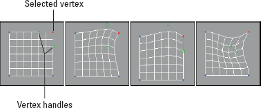
After you select Vertex subobject mode, you can transform selected vertices using the transform buttons on the main toolbar, or you can distort the faces around the selected vertex by transforming the handles, shown as small green squares. Dragging these handles changes the surface of the patch, as shown in Figure 6. The first patch shows the handles before being moved, the second patch shows the effect of moving the handles with the Lock Handles option enabled, the third patch has moved a single handle, and the fourth patch shows where both handles have been moved.
FIGURE 6 Moving the Vertex handles alters the adjacent faces.
Patch vertices can be either of two types: Coplanar or Corner. Coplanar vertices maintain a smooth transition from vertex to vertex because their handles are locked. This causes the handles to always move so as to prevent any surface discontinuities. You can drag the handles of corner vertices to create gaps and seams in the surface.
You can switch between these two vertex types by right-clicking a vertex while in vertex subobject mode and selecting the desired type from the pop-up quadmenu.
Note
Holding down the Shift key while clicking and dragging a handle unlocks the handles and automatically changes the vertex type to Corner.
Bind and Unbind
You can use the Bind button to connect edge vertices of one patch to an edge of another patch, which is useful for connecting edges with a different number of vertices. Be aware that the two patches must be part of the same object (you can make them part of the same object using the Attach button) and that the corner vertices must be welded together first. If you try to bind a vertex before welding the corner vertices, the Bind action won't work. To use the Bind feature, click the Bind button and then drag a line from a vertex to the edge where it should join.
The Bind button attaches vertices to edges; to attach vertices to vertices, use one of the Weld buttons. When you bind vertices, the point of contact between the two patches is seamless and the vertex becomes part of the interior. To exit Bind mode, click the Bind button again or right-click in a viewport.
You use the Unbind button to detach vertices that have been connected using the Bind button.
Create
You can use the Create button in the Vertex subobject mode to create patch vertices by clicking in the viewport. Use the Create button in Patch or Element subobject mode to connect the created vertices into three-sided or four-sided patches. Right-click in the viewport or click again on the Create button to exit Create mode.
The order in which you click the vertices determines the direction of the normal vector, which determines the visibility of the patch in the viewports (unless the Force 2-Sided display option is enabled). If you click the vertices in a clockwise direction, then the normal vector points away from the current viewport. The counterclockwise order points the normal vector out toward the user (which makes it visible).
Tip
An easy way to determine the direction of the normal vector is to curl the fingers on your right hand in the direction that the vertices were clicked. Your thumb points toward the direction of the normal vector. This is called the right-hand rule.
Delete
The Delete button (or pressing the Delete key) deletes the selected vertices. This button works for all the subobject types.
Note
Deleting a vertex also deletes all faces and edges connected to that vertex. For example, deleting a single (top) vertex from a sphere that has been converted to an Editable Patch object leaves only a hemisphere.
Break
Click the Break button to create a separate vertex for adjoining faces that are connected by a single vertex.
Patches are all connected by vertices: Moving one vertex changes the position of all adjoining patches. The Break button enables you to move the vertex associated with each patch independent of the others. The button is available only in Vertex subobject mode.
Hide and Unhide All
The Hide and Unhide All buttons hide and unhide selected vertices. They can be used in any subobject mode. To hide a subobject, select the subobject and click the Hide button. To unhide the hidden subobjects, click the Unhide All button. Clicking the Unhide All button makes all subobjects, regardless of type, visible.
Weld Selected and Weld Target
The Weld button enables you to weld two or more vertices into one vertex. To use this feature, move the vertices close to one another, drag an outline over them to select them, and then click the Weld button. You can tell whether the weld was successful by looking at the number of vertices selected at the bottom of the Selection rollout. If the weld was unsuccessful, increase the Weld Threshold specified by the spinner and try again.
The Weld Target button lets you select a vertex and drag and drop it on top of another vertex. If the target vertex is within the number of pixels specified by the Target value, the vertices are welded into one vertex. To exit Weld Target mode, click the Target button again or right-click in the viewport.
Figure 7 shows two inverted sloping patches that have been combined. The resolution of the patch on the right is twice that of the patch on the left. The Bind button was used to attach the center vertex to the edge of the other patch. Notice that the seam between the two patches is smooth.
FIGURE 7 Two patches of different resolutions have been combined using the Bind and Weld buttons.

Copy and Paste Tangents
Getting the handle positions between vertices just right can be tricky, but after you get it right, the Copy and Paste buttons in the Tangent section let you copy the handle orientation between vertices. The Paste Length option enables you to paste the length of the handle as well.
Vertex surface properties
In Vertex subobject mode, the Surface Properties rollout that appears lets you color the object by assigning colors to its vertices. For each vertex, you also can specify an Illumination color and an Alpha value, which sets the transparency. You also can specify vertex colors in Patch and Element subobject modes.
Cross-Reference
You can find more information on vertex colors in Chapter 34, “Creating Baked Textures and Normal Maps.”
After you assign colors, you can recall vertices with the same color by selecting a color (or illumination color) in the Select Vertices By section and clicking the Select button. The RGB values match all colors within the Range defined by these values. For example, if the RGB Range values are all set to 255, then every vertex is selected.
Editing handles
The Handle subobject mode gives you direct access to the vertex handles without the vertices or edges getting in the way. You can still work with handles in Vertex subobject mode, but the Handle subobject mode is more convenient and you don't need to worry about accidentally moving the vertex in the process.
When the Handle subobject mode is enabled, all vertex handles for the entire patch object are visible. Multiple handles can be selected and transformed at the same time. The Copy and Paste Tangent options are available for this mode also.
Editing edges
Edges are the lines that run between two vertices. You can select multiple edges by holding down the Ctrl key while clicking the edges or by holding down the Alt key to remove selected edges from the current selection set.
Many of the features in the Geometry rollout work in the same way as the Vertex subobjects, but the Geometry rollout also includes some features that are enabled in Edge subobject mode, like the ones in the following sections.
Subdivide
You use the Subdivide button to increase the resolution of a patch. This is done by splitting an edge into two separate edges, divided at the original edge's center. To use this feature, select an edge or edges and click the Subdivide button. The Propagate option causes the edges or neighboring patches to be subdivided as well. Using Subdivide without the Propagate option enabled can cause cracks to appear in the patch. The Subdivide button also works in Patch subobject mode.
In Figure 8, I subdivided a Quad Patch edge three times after selecting the upper-right corner edges.
FIGURE 8 By subdividing edge subobjects, you can control where the greatest resolution is located.

Add Tri and Add Quad
You can add Quad and Tri Patches to any open edge of a patch. To do this, select the open edge or edges and click the Add Tri or Add Quad button. You can locate all open edges using the Select Open Edges button in the Selection rollout. The new patch extends along the current curvature of the patch. To add a patch to a closed surface, like a box, you first need to detach one of the patches to create an open edge. This feature provides a way to extend the current patch.
Figure 9 shows a simple quad patch that was subdivided and then added to using the Add Quad button. This provides an easy way to quickly create a rough outline of an object that you want to model.
FIGURE 9 A quick outline of a key was created by selecting edge subobjects and adding Quad patches.

Create Shape
You can use the Create Shape button that appears at the bottom of the Geometry rollout in Edge subobject mode to create spline shapes from all the selected edges. To use this button, select several edge subobjects and click the button. A dialog box appears that allows you to name the new shape. You can then use the Select by Name dialog box (keyboard shortcut H) to select the newly created shape.
Tutorial: Modeling a shell
Now that you've seen all the various tools, it's time to try out some of them. You can use a Patch object to create a common beach shell, as you do in this tutorial.
To model a shell using a patch, follow these steps:
- Open the Patch seashell.max file from the Bonus Chapter 4 directory on the CD.
This file includes a simple disk that has been converted to an Editable Patch object, and all the lower vertices have been welded together.
- Select the shell object and open the Modify panel. Click the small plus icon to the left of the Editable Patch object in the Modifier Stack, and select Edge from the hierarchy (or press 2).
You are now in Edge subobject mode.
- Select every other interior set of radial edges in the Front viewport along the shell while holding down the Ctrl key. Make sure you select both the front and back edges. The Info line at the bottom of the Selection rollout tells you what is selected (14 edges should be selected). When you have the edges selected, press the spacebar to lock the selection.
- Click the Select and Move button (or press W), and move the edges upward in the Top view.
A zigzag pattern appears on the surface of the patch.
Figure 10 shows the completed shell.
Editing patch and element subobjects
Transforming a patch object containing only one patch works the same way in subobject mode as it works for normal transformations. Working with the patch subobject on an object that contains several patches lets you transform individual patches. A key advantage of working with the patch subobjects is controlling their Geometry using the buttons in the Geometry rollout. The following sections discuss the additional features available in patch subobject mode.
Detach
The Detach button separates the selected patch or element subobjects from the rest of the object. Using this button opens the Detach dialog box, which enables you to name the detached subobject. The Reorient option realigns the detached subobject patch to match the position and orientation of the current active patch. The Copy option creates a new copy of the detached subobject.
Note
This feature is different from Delete. Detach maintains the subobject and gives it a separate name, but the Delete function eliminates the subobject.
FIGURE 10 This shell is an Editable Patch created by moving every other interior edge.

Extrude
The Extrude button adds depth to a patch by replicating a patch surface and creating sides to connect the new patch surface to the original. For example, a square patch grid that is extruded forms a cube. To use this feature, select a patch, click the Extrude button, and then drag in a viewport—the patch interactively shows the extrude depth. Release the button when you reach the desired distance.
Alternatively, you can specify an extrude depth in the Extrusion spinner. The Outlining value lets you resize the extruded patch. Positive outlining values cause the extrusion to get larger, whereas negative values reduce its size. The Normal Group option extrudes all selected patches along the normal for the group, and the Normal Local option moves each individual patch along its local normal. To exit extrude mode, click the Extrude button again or right-click in the viewport.
Tip
One place to use this function is to add arms to the torso of a character. If you've created a torso model out of patches, you can add arms by detaching a patch and extruding the area where the arms go.
Figure 11 shows the key-shaped patch that has been extruded using the Extrude button.
FIGURE 11 The simple key-shaped patch has been extruded.

Bevel
The Bevel button extrudes a patch and then lets you bevel the edges. To use this feature, select a patch, click the Bevel button, and then drag in a viewport to the Extrusion depth and release the button. Then drag again to specify the Outlining amount.
You can use the same options for the Bevel button as for the Extrude button described earlier. In addition, the Bevel button includes Smoothing options for the bevel. Set the Start and End Smoothing options to Smooth, Linear, or None.
Patch and Element surface properties
If either the Patch or Element subobject mode is selected, the Surface Properties rollout appears. You can use this rollout to control normal vectors and assign Material IDs and Smoothing Groups.
The Surface Properties rollout includes Flip and Unify buttons to control the direction of the normal vectors. Flip reverses the direction of the normals of each selected face; Unify makes all normals face in the same direction based on the majority. The Flip Normal Mode button activates a mode where you can click individual faces and flip their normals. This mode stays active until you click the Flip Normal Mode button again or right-click in the viewport.
Material IDs are used by the Multi/Sub-Object material type to apply different materials to different patches within an object. By selecting a patch subobject, you can use this control to apply a unique material to each patch.
Cross-Reference
You can find more information on the Multi/Sub-Object material type in Chapter 16, “Creating and Applying Standard Materials.”
You also can assign a patch to a unique Smoothing Group. To do this, select a patch and click a Smoothing Group number.
Tutorial: Creating a maple leaf from patches
Because patches are a good modeling type for organic objects, let's put it to the test by trying to create a maple leaf. Because of the symmetry of the leaf, you really need to create only half of the leaf. You can then use the Mirror tool to create the other half.
To model a maple leaf using patches, follow these steps:
- Open the Maple leaf.max file from the Bonus Chapter 4 directory on the CD.
This file includes a background image of a real maple leaf loaded into the Front viewport.
- Select Create Patch Grids Tri Patch, and drag in the Front viewport to create a square patch grid from the base where the stem is to the upper-left interior area of the leaf. The right edge of the patch should run about halfway up along the midline of the leaf.
- In the Modify panel, right-click the Tri Patch name and select Convert to Editable Patch from the pop-up menu.
- In the Modifier Stack, select the Element subobject mode (or press the 4 key) and then select the patch element. With the Propagate option selected, click the Subdivide button.
- Select the Edge subobject mode (or press the 2 key), and select one of the edges that is completely within the interior area of the background leaf image. Then press the Add Tri button to extend the patch. Repeat this step until you have added a patch for each point around the outer perimeter of the leaf.
- Select Vertex subobject mode (or press the 1 key). With the Select and Move button on the main toolbar, select and drag the edge vertices so they align with the corners of the background leaf. Move all internal vertices so they lie within the leaf area. Select each vertex that lies along the outer edge of the leaf, and move its handles so the patch edge aligns with the background leaf's border. If the handles move together, hold down the Shift key to move them individually.
- Deselect the Vertex subobject mode. In the Surface Properties rollout, enable all the options, and set the Relax Value to 1.0 and the Iterations to 50. This smoothes out the wrinkles in the patch.
Figure 12 shows the completed maple leaf patch (half of it, anyway). To complete this leaf, use the Mirror tool and add a spline object for the stem.
FIGURE 12 By repositioning the vertex handles, you can make the patch object match the leaf's edges precisely.

Using Modifiers on Patch Objects
Several modifiers work specifically on patch objects. The Modifiers ![]() Patch/Spline Editing submenu contains most of these modifiers.
Patch/Spline Editing submenu contains most of these modifiers.
Tip
Many other modifiers work on patch objects. To see which modifiers work on patch objects, select the patch object and check the Modifiers menu to see which modifiers are enabled.
Patch Select modifier
The Patch Select modifier enables you to select patch subobjects, including Vertex, Edge, Patch, and Element. You can copy and paste named selection sets. The selection can then be passed up the Stack to the next modifier. The Patch Select modifier provides a way to apply a separate modifier to a subobject selection.
Edit Patch modifier
This modifier includes tools for editing patch objects. The features of this modifier are the same as those of the Editable Patch object. If you want to animate the features of an Editable Patch, use the Edit Patch modifier. You can even apply the Edit Patch modifier to an Editable Patch. The key benefit of the Edit Patch modifier is that it enables you to edit patch subobjects while maintaining the parametric nature of the object.
Delete Patch modifier
You can use the Delete Patch modifier to delete a patch subobject from a patch object. You use the Patch Select modifier to select the patch subobjects to delete, and you apply the Delete Patch modifier to the Patch Select modifier.
Using the Surface tools
The surface tools, which include the CrossSection and Surface modifiers, provide a way to model that is similar to lofting. The CrossSection modifier takes several cross-section splines or shapes and connects their vertices with additional splines to create a spline framework. You can then use the Surface modifier to cover this framework with a skin.
Cross-Reference
Lofting is accomplished with the Loft compound object. For more information on it, see Chapter 27, “Working with Compound Objects.”
CrossSection modifier
The CrossSection modifier and the Surface modifier are the key reason why the spline and patch modifiers have been combined into a single submenu.
The CrossSection modifier works only on spline objects. This modifier connects the vertices of several cross-sectional splines together with another spline that runs along their edges like a backbone. The various cross-sectional splines can have different numbers of vertices. Parameters include different spline types such as Linear, Smooth, Bézier, and Bézier Corner.
To apply this modifier, all the cross-section splines must belong to the same Editable Spline object. You can connect them using the Attach button. The cross-section splines are attached in the order they exist, which can be a problem if you create them in a different order. The object to the left in Figure 13 shows a spline network that has been created with the CrossSection modifier.
Note
Editable Splines include a CrossSection feature that works just like the CrossSection modifier.
Surface modifier
The Surface modifier is the other part of the surface tools. It creates a surface from several combined splines. It can use any spline network, but works best with structures created with the CrossSection modifier. The surface created with this modifier is a patch surface.
Parameters for this modifier include a Spline Threshold value and options to Flip Normals, Remove Interior Patches, and Use Only Selected Segments. You also can specify the steps used to create the patch topology. After the surface is created, you can apply the Edit Patch modifier to further edit and refine the patch surface.
In order for the surface to be created correctly, the vertices of the spline cage should be as close to coincident as possible. The Threshold value represents how close they have to be before they are considered coincident. In addition, any closed loop in the spline cage can have no more than four vertices, or a patch is not created.
FIGURE 13 The CrossSection modifier joins several cross-section splines into a network of splines ready for a surface.

Note
If the structure is already created, you can create a surface from the splines by simply applying the Edit Patch modifier.
The object to the right in Figure 13 shows the spline structure with the Surface modifier applied.
Tutorial: Modeling a brass swan
Chapter 2 shows you how to add a background image of a brass swan to the viewports. In this tutorial, you use the CrossSection and Surface modifiers to create a swan based on these background images.
To create a brass swan, follow these steps:
- Open the Brass swan.max file from the Bonus Chapter 4 directory on the CD.
This file includes the background images needed to create the swan model.
- Select Create Shapes Ellipse, and drag in the Top viewport to create a simple ellipse that is roughly the shape of the swan's nose. Use the transform tools to move, rotate, and scale the ellipse to match the cross section of the background image.
- Hold down the Shift key, and drag the ellipse shape to the base of the swan's nose to create a clone. Use the transform tools to align this clone to the background image in the Front and Left viewports.
Note
Although background images have been loaded for the Top, Front, and Left viewports, you need only two viewports to align all the cross sections. In this example, the Top viewport is misaligned with the other two viewports.
- Continue to create cloned copies of the ellipse shape and match them to each changing cross section in the background images.
- For the base cross sections, right-click the ellipse shape and select Convert to Editable Spline from the pop-up quadmenu. Then enable Vertex subobject mode, click the Refine button in the Geometry rollout, and click the lower-left and lower-right corners of the ellipse to add two new vertices to the shape. Select and right-click these new vertices, and change their vertex type to Bézier Corner to make the bottom of their cross-section shapes flat.
- Select the first cross-section shape at the swan's nose, and convert it to an Editable Spline. Then click the Attach button, and select each cloned cross-section shape in order from the nose to the tail. This makes all the shapes part of the same Editable Spline object.
- Choose Modifiers Patch/Spline Editing CrossSection to apply the CrossSection modifier to the Editable Spline object. Then choose Modifiers Patch/Spline Editing Surface to apply the Surface modifier. Next, you may need to enable the Flip Normals option to see the final swan model. This command creates a surface that covers the spline framework. The surface created is a patch object.
Note
You may not need to enable the Flip Normals option depending on how you created your initial splines.
Figure 14 shows the completed swan model. Using the surface tools to create patch objects results in objects that are easy to modify. You can change any patch subobject by applying the Edit Patch modifier and using the rollouts in the Modify panel.
Another way to create this swan model is to use the CrossSection feature for the Editable Spline and then apply the Edit Patch modifier to create the finished surface. This method is cleaner and involves fewer modifiers.
FIGURE 14 The brass swan was created using the CrossSection and Surface modifiers.

Cross-Reference
Another common modifier that is used with patch objects is PatchDeform. Learn more about this modifier in Chapter 21, “Understanding Animation and Keyframes.”
Summary
Patches don't have the overhead of NURBS objects and are better optimized than mesh objects. Editable Patch objects include a huge list of tools you can use to edit and modify them. More specifically, this chapter covered the following topics:
- Creating Quad Patch and Tri Patch grids
- Discovering the features of an Editable Patch object
- Working with the Editable Patch subobjects
- Working with patch-specific modifiers such as the surface tools