
BONUS CHAPTER 5
Working with NURBS
Lofting a NURBS surface
Creating a UV Loft surface
Lathing a NURBS surface
Creating a 1-rail and 2-rail sweep surface
Sculpting a rectangular NURBS surface
You learn many details of working with NURBS as you dive in and start building NURBS objects. This bonus chapter includes several tutorials that can help as you try to grasp the power and flexibility of modeling with NURBS.
Lofting a NURBS Surface
U Loft is one of the most versatile NURBS surface tools: You can use it to create simple or very complex surfaces. In the following tutorial, you create a spoon by lofting a NURBS surface over a series of point curve cross sections using the U Loft tool. This tool requires sections in the horizontal (U) direction.
Tutorial: Creating a U Loft NURBS Spoon
Lofting a skin over a series of cross-section curves can create NURBS surfaces. In this tutorial, you create the point curves necessary for modeling a NURBS spoon. Then you use the U Loft tool to skin the surface and create the finished spoon.
To create a NURBS spoon using the U Loft feature, follow these steps:
- Open the U-Loft spoon.max file from the Bonus Chapter 5 directory on the CD.
This file includes 10 cross-section NURBS point curves that are correctly positioned to form a spoon.
- Select one of the curves, and open the Modify panel. In the General rollout, click the Attach Multiple button to open the Attach Multiple dialog box, click the All button to select all the curves, and then click the Attach button to attach all the curves to the first curve you selected.
- You are now ready to loft the spoon's surface with the U Loft tool. In the General rollout, click the NURBS Creation Toolbox icon to open the NURBS Toolbox window. In the Surfaces section, select the Create U Loft Surface icon.
The cursor changes to a pointer accompanied by the U Loft Surface icon. (Notice that when you place the cursor over a cross section, it changes to a cross and the curve turns blue.)
Note
You also can create this surface using the U Loft button found in the Create Surfaces rollout.
- Click the smallest cross section at the tip of the spoon, drag to the next adjacent curve, and click again.
The first section of the lofted NURBS surface is then generated as indicated by the green isoparm lines displayed in the viewport.
- Continue clicking each curve in sequential order until you have lofted the entire spoon. After you click the final section, right-click to exit this mode.
- Now cap the ends by returning to the NURBS Toolbox window, select the Create Cap Surface tool, which is also located in the Surfaces section of the toolbox, and click each small end curve.
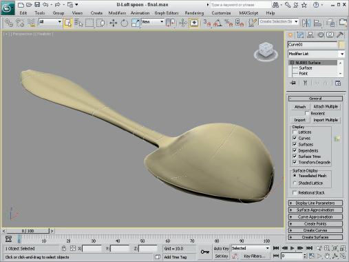
Figure 1 shows the completed NURBS spoon.
FIGURE 1 A NURBS spoon created with the U Loft tool
Creating a UV Loft Surface
A UV Loft surface can have more complex contours than a U Loft surface. UV Lofts are created from several curves spanning two dimensions; the U dimension is horizontal, and the V dimension is vertical. To use this tool, select the cross-section curves in the order that they will be skinned along the U dimension, right-click in the viewport, and click the cross-sectional curves for the V dimension. The resulting surface is made up of cross-sectional curves for both dimensions to create a complex NURBS surface. Just like the U Loft surface, all curves need to be attached to the same NURBS object.
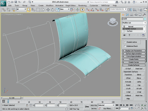
As an example, Figure 2 shows a chair seat that has been created with the UV Loft tool using three curves in the U direction and five curves in the V direction, thus enabling the surface to be contoured to fit a human being without you having to go back later and modify it by moving control vertices.
FIGURE 2 A UV Loft surface lofted from two sets of curves
This technique is very useful for building mechanical shapes, automobiles, and spaceships, and for modeling product designs.
Lathing a NURBS Surface
Lathing a NURBS curve works the same way as lathing a spline. You simply need to select a curve, click the Lathe button in the Create Surface rollout (or click the Create Lathe Surface button in the NURBS Creation Toolbox), and then click the curve. You can change the Degrees value and the axis of rotation in the Lathe Surface rollout that appears under the Create Surfaces rollout in the Modify panel.
Tutorial: Lathing a NURBS CV Curve to Create a Vase
In this tutorial, you create a NURBS CV curve profile shape. You then use this curve with the Lathe modifier to create a vase.
To create a Lathed NURBS surface, follow these steps:
- Open the Lathed NURBS vase.max file from the Bonus Chapter 5 directory on the CD.
This file includes two CV curves that you can lathe to create a vase.
- Select one of the CV curves, open the Modify panel, and click the Lathe button in the Create Surfaces rollout (or click the Create Lathe Surface button in the NURBS Creation Toolbox). In the Lathe Surface rollout that appears at the bottom of the Modify panel, enter a value of 360 in the Degrees field and click the Y-axis button. Then click both CV curves to complete the lathe. Click the Lathe button again to exit Lathe mode.
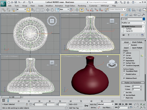
Figure 3 shows the completed vase produced using the Lathe tool.
FIGURE 3 The lathed CV surface vase
Creating a 1-Rail and 2-Rail Sweep Surface
The 1-rail sweep surface tool lets you create a NURBS surface by using one NURBS curve to act as a side rail and one or more profile shape curves to sweep along the rail to generate the surface. A 2-rail sweep surface is similar, except that it uses two NURBS curves as side rails.
Tutorial: Creating a Flower Stem
Now that you have carefully constructed a flower vase, you need to create some flowers to place in the vase. You start with the flower stem.
To create a NURBS point surface using a 1-rail sweep, follow these steps:
- Open the Flower stem.max file from the Bonus Chapter 5 directory on the CD.
This file includes three cross sections and a curve correctly positioned that you can sweep to form a flower stem.
- Select the long stem curve. Open the Modify panel, click the Attach button, and then click the three cross-section shapes. Click the Attach button again to exit attach mode.
- Open the Create Surfaces rollout, and click the 1-Rail (Sweep) button (or click the Create 1-Rail Sweep button in the NURBS Creation Toolbox). Click the long stem curve, and then click the cross-section shapes in order from the bottom to the top. Right-click to end the creation of the 1-rail sweep.
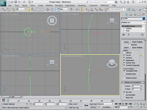
The NURBS skin is generated on the stem, as shown in Figure 4.
FIGURE 4 A stem created with a 1-rail sweep
Sculpting a Rectangular NURBS Surface
NURBS patches are a quick way to create a surface that can be sculpted using the subobject elements, such as a control lattice. For each subobject type, you can use many different tools to form the patch.
Tutorial: Creating a NURBS leaf
In this tutorial, you create a NURBS CV surface plane sculpted into a leaf for the NURBS flower. To do this, you work in the Surface CV subobject level and use the Select and Move transform tool to move CVs and sculpt the NURBS rectangle into a leaf shape.
To create a rectangular NURBS CV surface, follow these steps:
- Select Create
 NURBS CV Surface, and in the Create Parameters rollout, increase the Length CVs to 6 and Width CVs to 6. Click the Generate Mapping Coords check box.
 - In the Top viewport, click and drag to create the NURBS surface. In the Create Parameters rollout, set both the Length and Width to 180. While still in the Top viewport, rotate the NURBS surface 45 degrees along the Z-axis using the Select and Rotate tool so that it looks like a diamond shape.
- With the NURBS surface selected, open the Modify panel and click the plus sign to the left of the NURBS Surface object to gain access to the subobjects. Select the Surface CV subobject.
The CV lattice is displayed in the Top viewport.
- Select the Non-Uniform Scale tool (R), constrain it to the X-axis (F5), and then drag-select the middle horizontal row of CVs. Scale them down (narrower) to 85 percent.
- Select the middle three horizontal rows of CVs (including the one just scaled) and scale them down to 90 percent. Then select the middle 5 horizontal rows and scale them down to 90 percent.
This step gently rounds the outside contours of the NURBS surface.
- In the Front viewport, you should see the edge of the NURBS surface. Maximize the viewport and then select the Rotate tool, constrain it to the Z-axis, and select the right half of the CVs, but do not select the CVs at the very center. Rotate the CVs upward –60 degrees.
- Repeat the select-and-rotate process with the CV on the left half of the center, but do not alter the CVs at the very center.
The leaf should now be U-shaped.
- Click the Move tool (W), constrain it to the Y-axis (F6), and then select the center row of CVs and move them downward –40 units to make a deep V shape.
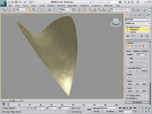
Figure 5 shows the NURBS leaf with the control lattice visible.
FIGURE 5 Translating CVs to sculpt a NURBS leaf
Tutorial: Sculpting a flower petal
Continuing to build your flower, you now sculpt a second rectangular NURBS surface into the shape of a flower petal. In this case, the center CVs of the surface are raised to create a soft, rounded shape. You sculpt one end of the NURBS rectangle into a blossom petal shape and then scale and clone it to create three more petals.
To sculpt the flower petal shape, follow these steps:
- Select Create NURBS CV Surface, and in the Keyboard Entry rollout, create a NURBS rectangular surface 80 units long and 80 units wide, with 6 Length CVs and 6 Width CVs.
- Select the Rotate tool (or press the E key), and in the Top view, rotate the surface 45 degrees. Open the Modify panel, click the plus sign to the left of the NURBS Surface object, and select the Surface CV subobject.
- Select the Non-Uniform Scale tool (R), and constrain it to the X-axis (F5). Then select the center horizontal row of CVs and scale it down (narrower) to 86 percent.
This step rounds the outside corners of the petal.
- Drag-select the six CVs that make up the upper tip of the petal. Use the non-uniform-scale feature on the triangle of CVs in the Y-axis and bring them down to 35 percent to blunt the point at the top of the petal.
- Click and drag a selection box around all the CVs in the center of the petal (don't select any CVs on the edges). You can use the Ctrl key to add CVs to the selection and the Alt key to remove CVs from the selection. In the Front viewport, select the Move tool and move the CVs upward six units in the Y-axis to round the top of the petal.
- In the Top viewport, select the lower half of the center vertical column of CVs, click the Lock Selection icon (or press the spacebar), and in the Front viewport, use the Move tool to move the CVs seven units downward in the Y-axis. When a groove appears halfway down the center of the petal, unlock the selection set.
- To clone the petal, turn off subobject mode and activate the Top viewport. Select World from the Reference Coordinate System drop-down list. Click the Mirror icon to open the Mirror: Screen Coordinates dialog box, and then clone the petal by selecting the Y-axis and Copy options. Move the new petal downward in the Y-axis so that the points of the petals touch.
- Now clone the petals again, but make them smaller. Select the Uniform Scale button (or press the R key), select both petals in the Top viewport, and then press the Shift key and scale the petals down to 40 percent to create smaller cloned versions of the petals. Lock the selection set (press the spacebar), click Rotate (E), and then rotate the small petals 90 degrees to finish the blossom.
Figure 6 shows the completed flower.
FIGURE 6 Flower petals that were sculpted using NURBS

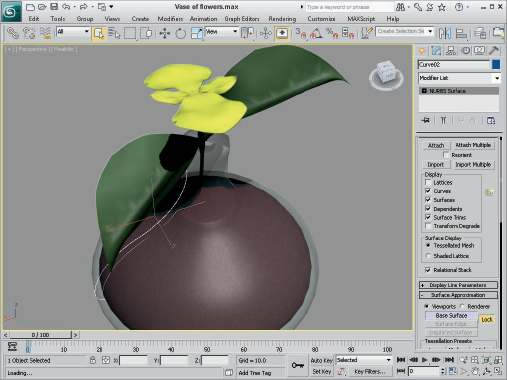
To finish the flower and vase model, you need to merge all the parts of the flower vase project into one scene. Clone and position the leaves next to the stem. Position the stem in the throat of the vase at a slight angle. Position the leaves midway up the stem and then place the flower at the top of the stem, at right angles to the leaves. Finally, apply texture maps to all objects, using a glass material for the vase, dark green for the leaves and stem, and a yellow radial gradient for each petal of the blossom. The finished flower is shown in Figure 7.
FIGURE 7 A vase and flower built completely from NURBS
Using NURBS Modifiers
The Modifiers ![]() NURBS Editing menu includes a set of modifiers unique to NURBS objects. This set includes the following modifiers: Surface Select, Surf Deform, and Disp Approx.
NURBS Editing menu includes a set of modifiers unique to NURBS objects. This set includes the following modifiers: Surface Select, Surf Deform, and Disp Approx.
The NURBS Surface Select modifier (known in the Modifier List as NSurfSel) lets you make a subobject selection for the selected NURBS object. This selection is then passed up the Modifier Stack to the next modifier. The two subobjects for this modifier are Surface CV and Surface.
The Surf Deform modifier works on NURBS surfaces just like the PatchDeform and PathDeform modifiers. After applying this modifier, you can select another NURBS object with the Pick Object button to deform the selected NURBS object. This modifier also has a World-Space version.
The Displacement Approximation (or Disp Approx) modifier makes displacement mapping (which is applied using materials) available in the Modifier Stack. This modifier alters the surface of an object based on displacement mapping. This modifier can work with any object that can be converted to an Editable Mesh, including primitives, NURBS, and Patches. Parameters for this modifier include Subdivision Preset settings of Low, Medium, and High.
The Displace NURBS World-Space modifier is similar to the Disp Approx modifier. It can convert a NURBS object into a mesh object and includes the effect of a displacement map. In the Displace NURBS rollout, you can select the Tessellation method to be Regular, Parametric, Curvature, or Spatial; or both Spatial and Curvature.
Note
Because U and V curves implicitly define a NURBS object's surface, they don't require mapping modifiers.
Summary
NURBS are an ideal method for modeling if you require free-flowing models. This chapter covered the following topics:
- Creating CV and point curves
- Discovering how to convert primitives to NURBS objects
- Creating NURBS surfaces from curves
- Learning to edit NURBS curves and surfaces
- Using NURBS subobject tools
- Lofting surfaces from point and CV curves
- Creating NURBS surfaces by lathing and sweeping