Nanofluid Conductive Heat Transfer in Solidification Mechanism
Abstract
Latent heat thermal energy storage systems (LHTESS), which work based on energy storage and retrieval during solid–liquid phase change is used to establish balance between energy supply and demand. LHTESS stores and retrieves thermal energy during solid–liquid phase change, while in SHTESS phase change doesn’t occur during the energy storage and retrieval process. LHTESS has a lot of advantages in comparison to SHTESS; the most important one is storing a large amount of energy during phase change process, which makes the energy storage density in LHTESS much higher than SHTESS. Due to this property, LHTESS have a wide application in different cases, such as solar air dryer, HVAC systems, electronic chip cooling, and engine heat recovery. The main restriction for these systems is thermal conductivity weakness of common PCMs. In this chapter, the method of adding nanoparticles to pure PCM and making nanoenhanced phase change material (NEPCM) and using fin with suitable array are presented to accelerate solidification process. The numerical approach, which is used in this paper is standard Galerkin finite element method.
Keywords
8.1. Discharging process expedition of NEPCM in Y-shaped fin-assisted latent heat thermal energy storage system
8.1.1. Problem definition and Mathematical model
8.1.1.1. Problem definition
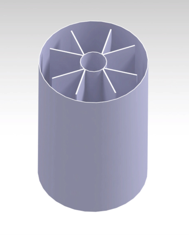
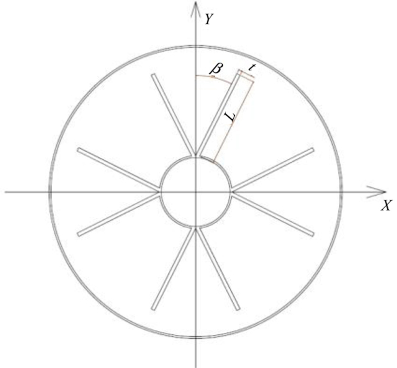
Table 8.1
The physical properties of water as PCM, copper as nanoparticles, and aluminum fin
| Property | PCM | Nanoparticles | Fin |
| ρ (kg/m3) | 997 | 8,954 | 2,700 |
| Cp (J/kg K) | 4179 | 385 | 902 |
| k (W/mK) | 0.6 | 400 | 200 |
| Lf (J/kg) | 335,000 | — | — |

 (8.1)
(8.1)
 (8.2)
(8.2)
 (8.6)
(8.6)
 (8.7)
(8.7)8.1.1.2. Numerical method
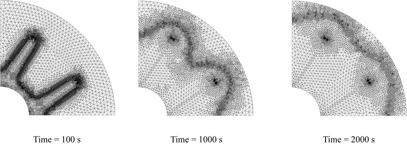

8.1.2. Effects of active parameters
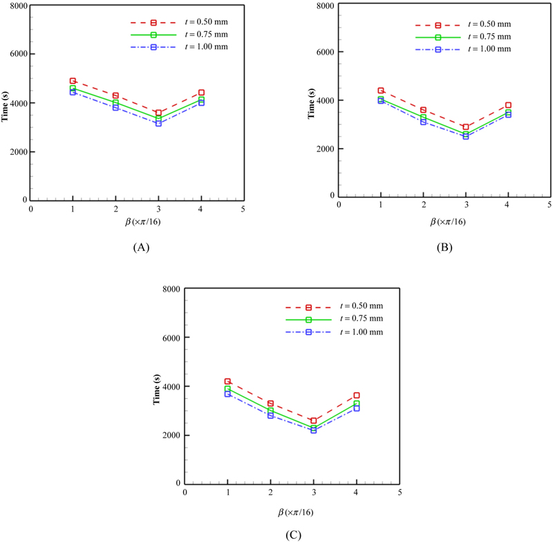
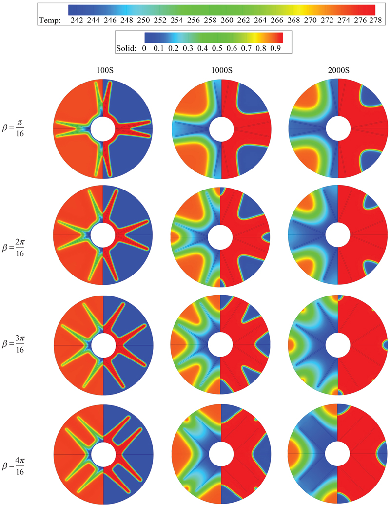
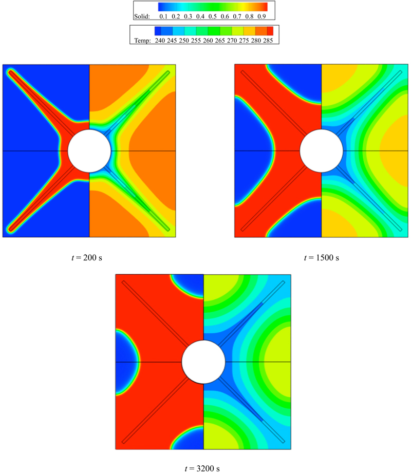
8.1.2.1. Applying Y-shaped fin to LHTESS
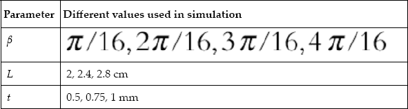
Table 8.2
Geometry parameters of Y-shaped fins
| Parameter | Different values used in simulation |
| β |
|
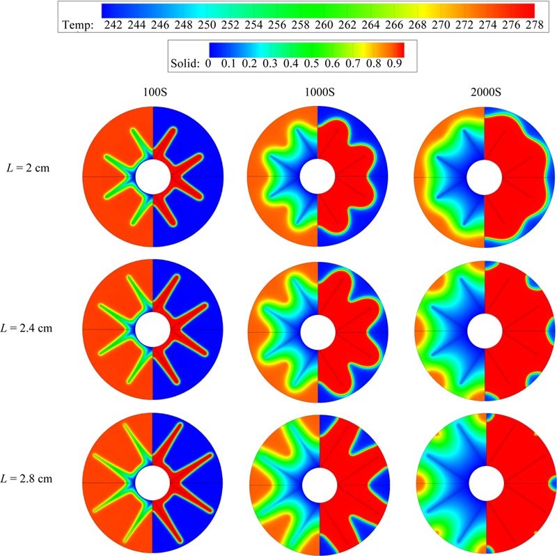
| L | 2, 2.4, 2.8 cm |
| t | 0.5, 0.75, 1 mm |

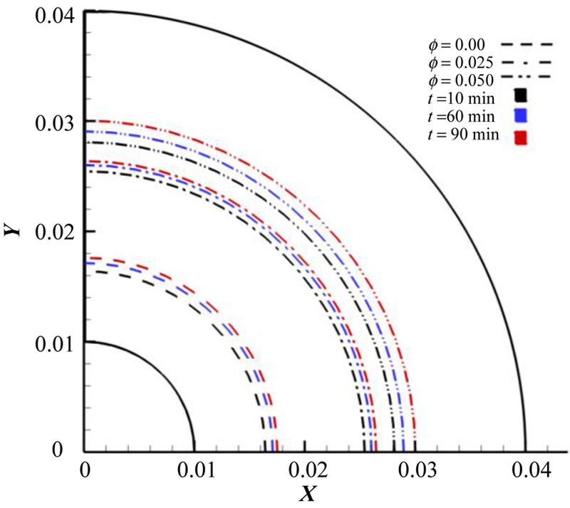
8.1.2.2. Adding nanoparticles to LHTESS
Table 8.3
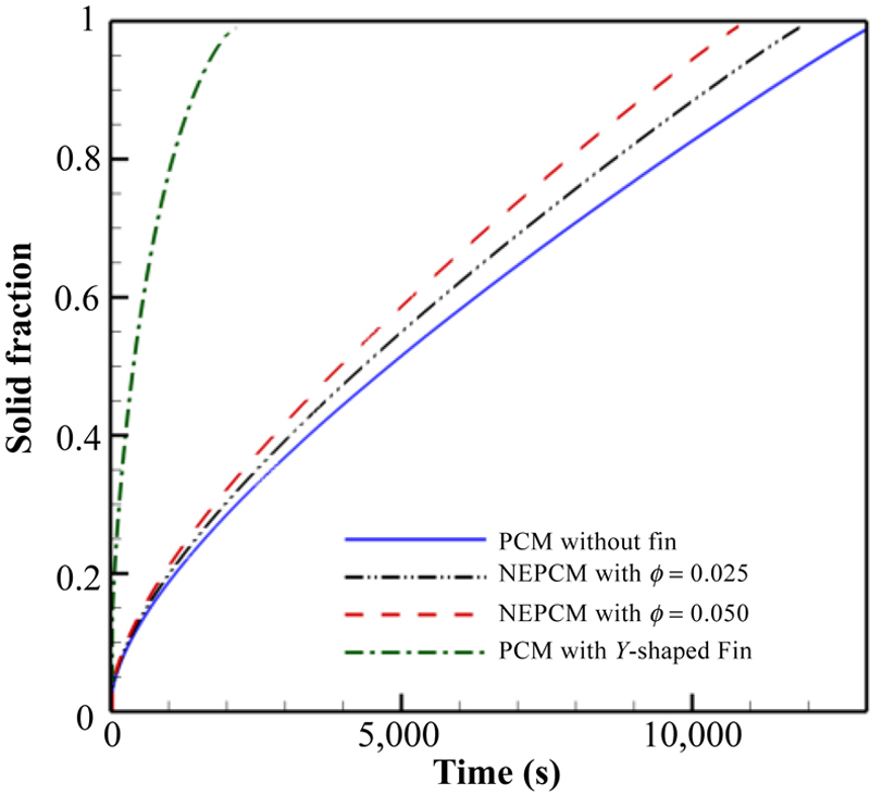
Effect of nanoparticles volume fraction on full solidification time and improvement
| Nanoparticle volume fraction (φ) | Full solidification time (s) | Increment in rate of solidification (%) |
| 0.00 | 13,000 | — |
| 0.025 | 11,847 | 8.8 |
| 0.050 | 10,800 | 16.9 |
8.1.2.3. Comparison between adding nanoparticles and applying Y-shaped fins

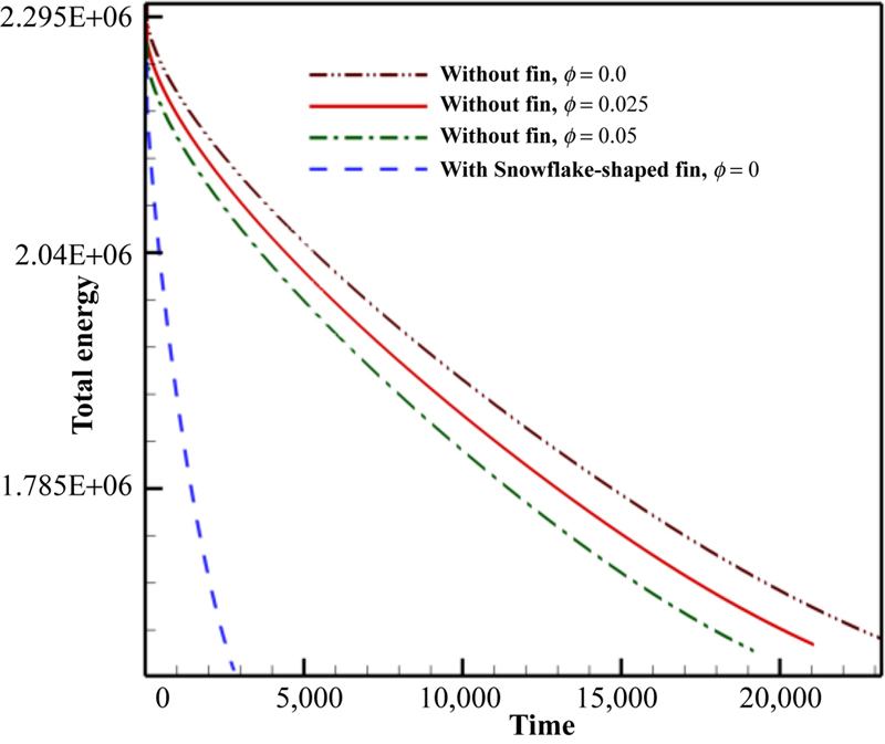
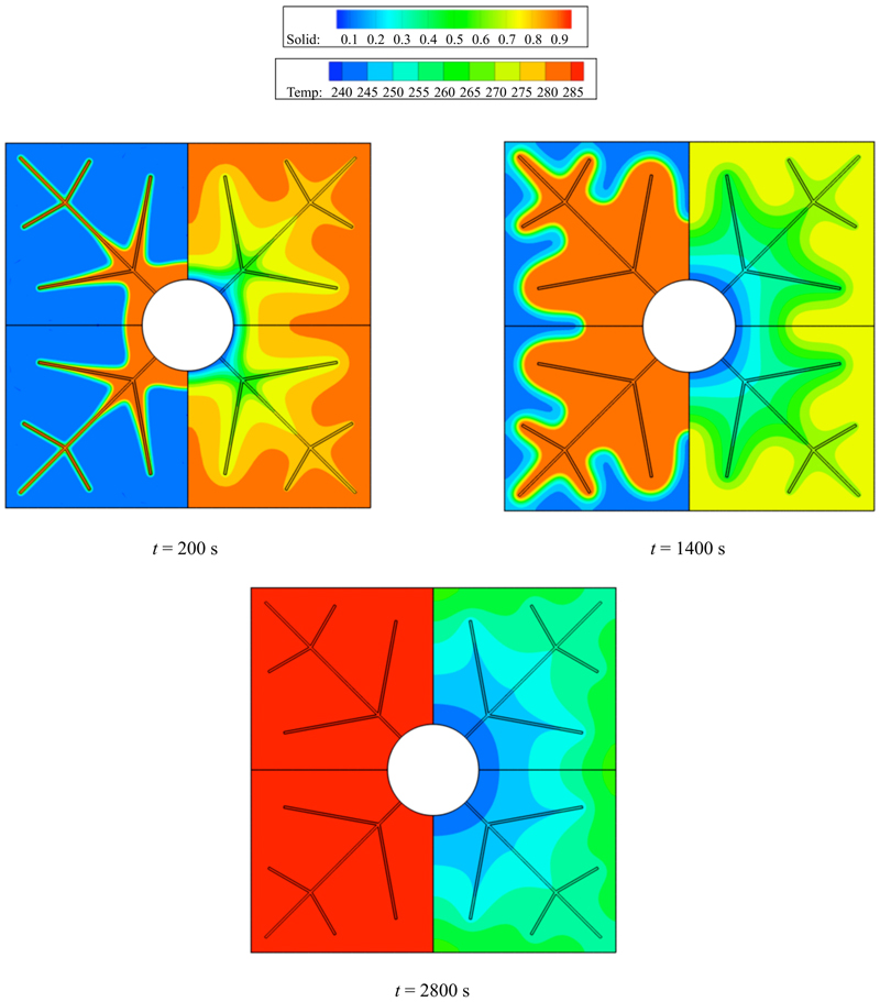
8.2. Snowflake-shaped fin for expediting discharging process in latent heat thermal energy storage system containing nanoenhanced phase change material
8.2.1. Problem statement
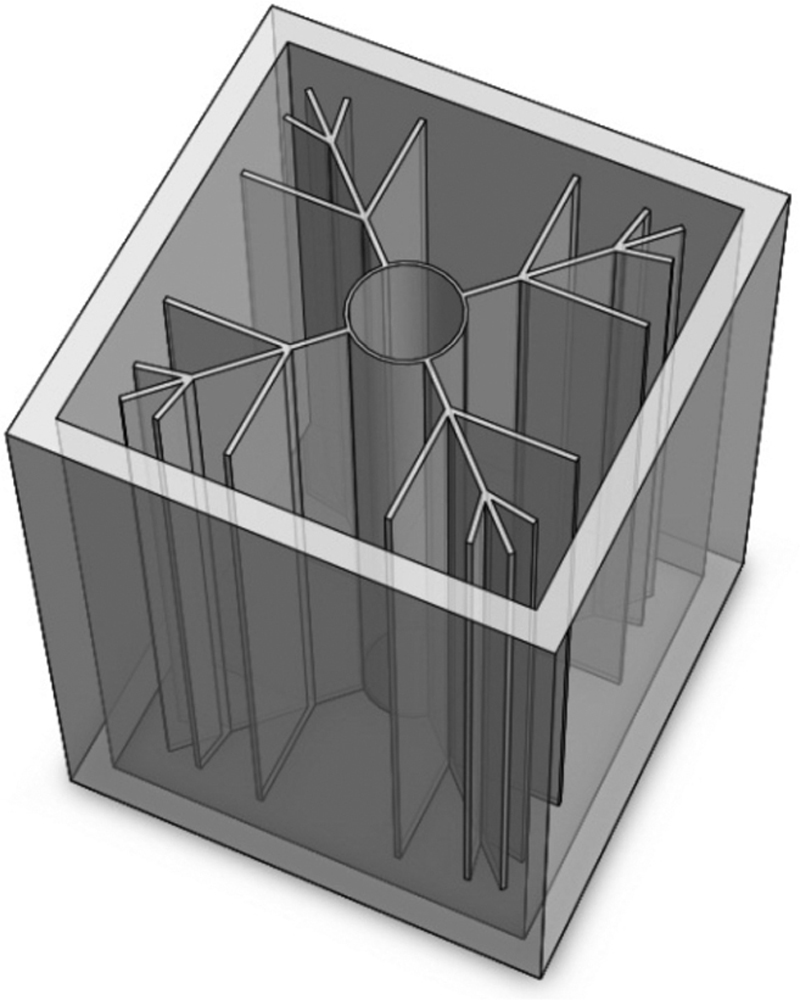

Table 8.4
Geometry parameters of Snowflake-shaped fin structure
| Geometry parameters | Values |
| β1 | [2π/12–5π/12] [Rad] |
| β2 | [2π/12–5π/12] [Rad] |
| X1 | 0.1L, 0.2L |
| X2 | 0.6L, 0.7L |
8.2.2. Numerical results

 (8.8)
(8.8)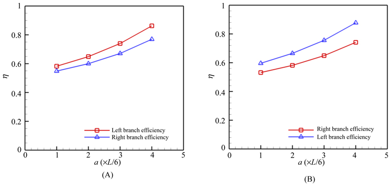

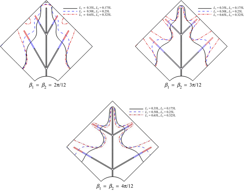
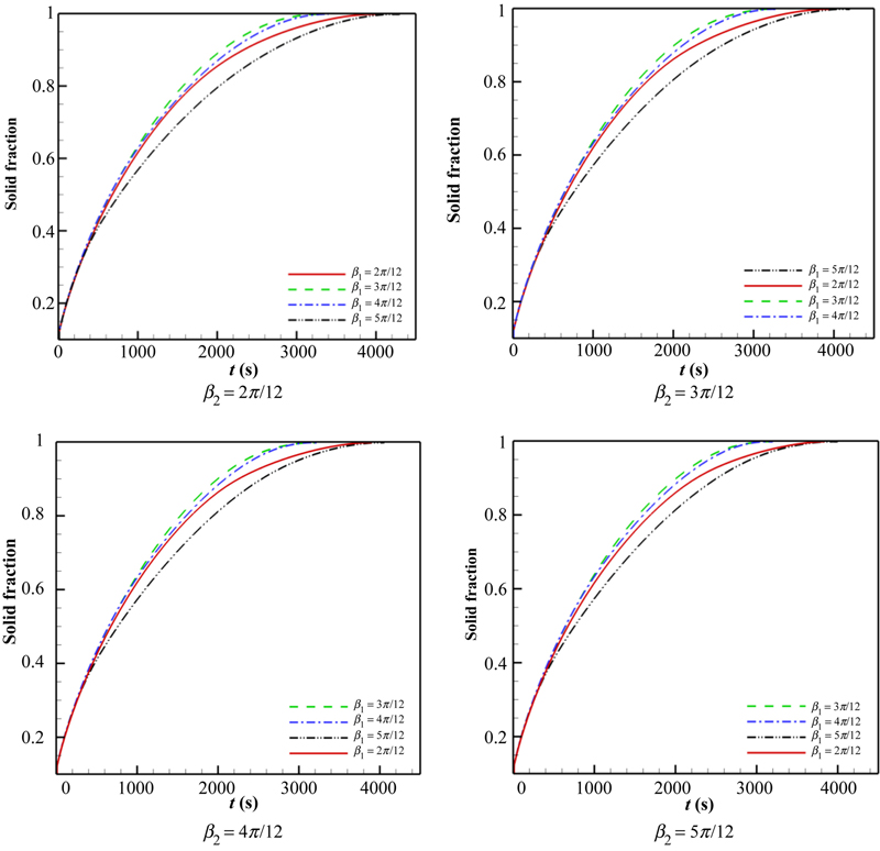
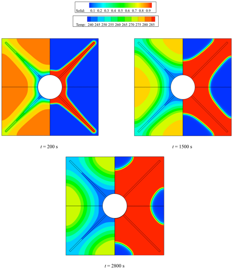
8.2.2.1. Effect of branches direction on solidification rate
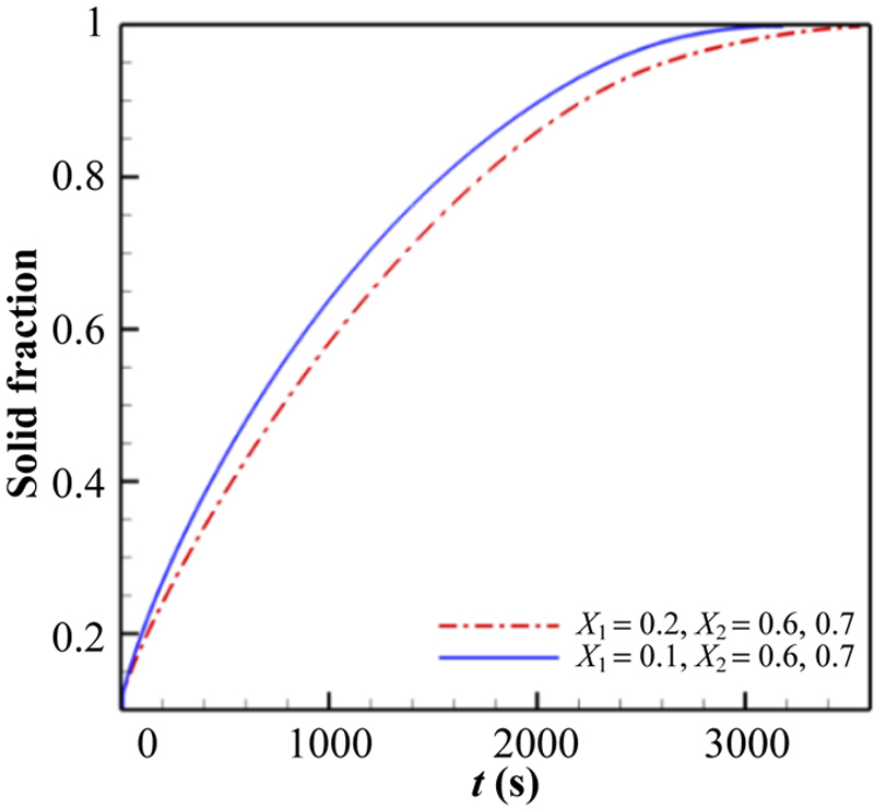
8.2.2.2. The effect of changing the distance between the branches on solidification rate
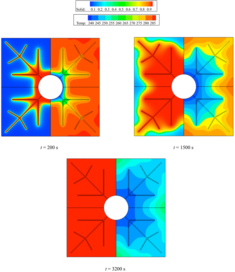
8.2.2.3. Performance enhancement of discharging process in LHTESS by adding fins

 (8.9)
(8.9)8.2.2.4. Optimization of the Snowflake-shaped fin configuration
8.2.2.4.1. Effect of bigger branch direction on solidification rate
8.2.2.4.2. Effect of smaller branch direction on solidification rate
8.2.2.4.3. Effect of bigger branch distance from cold wall on solidification rate
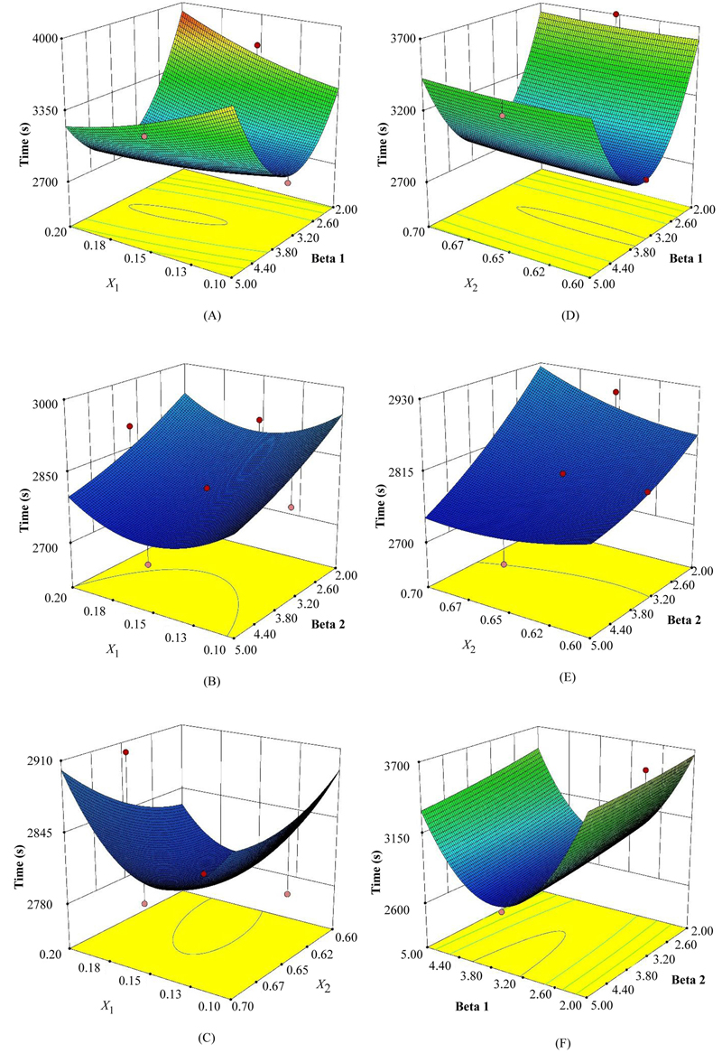
8.2.2.4.4. Effect of smaller branch distance from cold wall on solidification rate
8.2.2.5. Performance enhancement of discharging process in LHTESS by adding various structures of fin
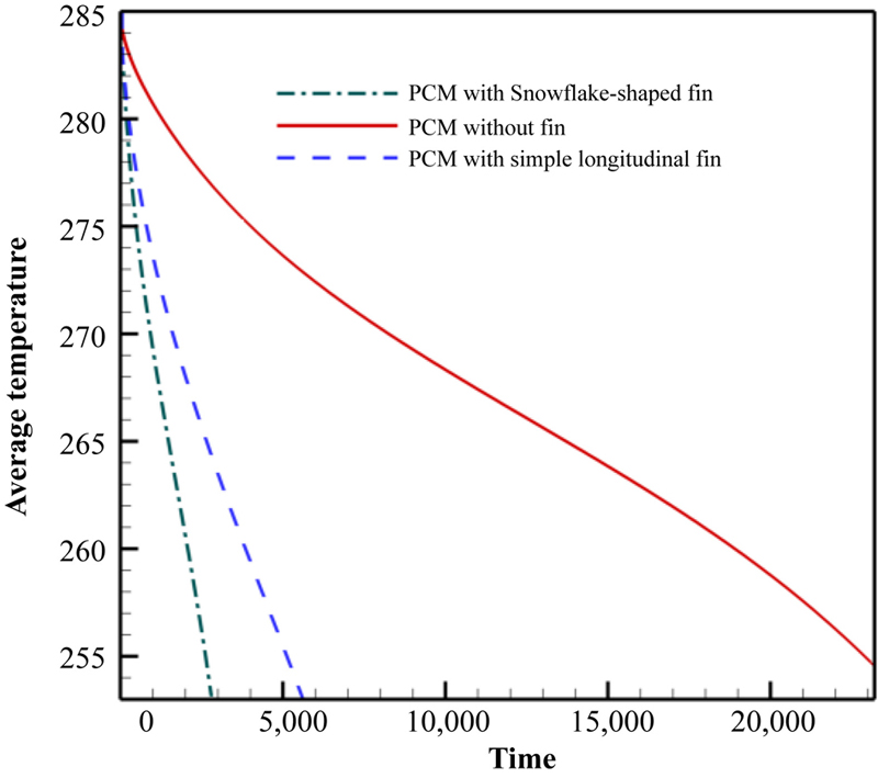
8.2.2.6. Comparison between the enhancement techniques