Developing a setup strategy
Starting a new drawing
Setting up model space
Creating and using drawing templates
Surprisingly, drawing setup is one of the trickier aspects of using AutoCAD. It's an easy thing to do incompletely or incorrectly, and AutoCAD 2009 doesn't provide a simple, one-click tool to help you do all of it right. And yet, drawing setup is a crucial thing to get right. Setup steps that you omit or don't do right may come back to bite you later.
Sloppy setup really becomes apparent when you try to plot (print) your drawing. Things that seemed more or less okay as you zoomed around on the screen are suddenly the wrong size or scale on paper. And nothing brands someone as a naive AutoCAD wannabe as quickly as the inability to plot a drawing at the right size and scale. Chapter 5 covers plotting procedures, but the information in this chapter is a necessary prerequisite to successful plotting and sheet setup. If you don't get this stuff right, there's a good chance you'll find that ...the plot sickens.
This chapter describes the decisions you need to make before you set up a new drawing, shows the steps for doing a complete and correct setup, and demonstrates how to save setup settings for reuse.
Warning
Don't assume that you can just create a new blank DWG file and start drawing things. Do read this chapter before you get too deep into the later chapters in this book. Many AutoCAD drawing commands and concepts depend on proper drawing setup, so you'll have a much easier time of drawing and editing things if you've done your setup homework. A few minutes invested in setting up a drawing well can save hours of thrashing around later on.
After you've digested the detailed drawing setup procedures described in this and the following chapter, use the AutoCAD Drawing Setup Roadmap on the Cheat Sheet at the front of this book as a quick reference to guide you through the process.
You have to set up AutoCAD correctly, partly because AutoCAD is so flexible and partly because, well, you're doing CAD — computer-aided drafting (or design). The computer can't aid your drafting (or design) if you don't clue it in on things like system of measure, drawing scale, paper size, and units. In this context, the following facts help explain why AutoCAD drawing setup is important:
Electronic paper: The most important thing you can do to make using AutoCAD fun is to work on a correctly set up drawing so that your screen acts like paper, only smarter. When drawing on real paper, you constantly have to translate between units on the paper and the real-life units of the object you're drawing. But when drawing in AutoCAD's smarter paper, you draw directly in real-life units — feet and inches, millimeters, or whatever you typically use on your projects. AutoCAD can then calculate distances and dimensions for you and add them to the drawing. You can make the mouse pointer jump directly to preset intervals on-screen, and a visible, resizable grid gives you a better sense of the scale of your drawing. However, this smart paper function works well only if you tell AutoCAD some crucial parameters for your specific drawing. AutoCAD can't really do its job until you tell it how to work.
Dead-trees paper: Creating a great drawing on-screen that doesn't fit well on paper is all too easy. After you finish creating your drawing on the smart paper AutoCAD provides on-screen, you then usually have to plot it on the good, old-fashioned paper that people have used for thousands of years. At that point, you must deal with the fact that people like to use certain standard paper sizes and drawing scales. (Most people also like everything to fit neatly on one sheet of paper.) If you set up AutoCAD correctly, good plotting results automatically; if not, plotting time can become one colossal hassle.
It ain't easy: AutoCAD provides templates and Setup Wizards for you, but the templates don't work well unless you understand them, and some of the wizards don't work well even if you do understand them. This deficiency is one of the major weaknesses in AutoCAD. You must figure out on your own (with the help of this book, of course) how to make the program work right. If you just plunge in without carefully setting up, your drawing and printing efforts are likely to wind up a real mess.
Fortunately, setting up AutoCAD correctly is a bit like following a roadmap to a new destination. Although the directions for performing your setup are complex, you can master them with attention and practice. Even more fortunately, this chapter provides a detailed and field-tested route. And soon, you'll know the route like the back of your hand.
Tip
While you're working in AutoCAD, always keep in mind what your final output should look like on real paper. Even your first printed drawings should look just like hand-drawn ones — only without all those eraser smudges.
Before you start the drawing setup process, you need to make decisions about your new drawing. The following four questions are absolutely critical; if you don't answer them or your answer is wrong, you'll probably need to rework the drawing later:
In some cases, you can defer answering one additional question, but it's usually better to deal with it up front: What kind of border or title block does your drawing require?
Warning
If you're in a hurry, it's tempting to find an existing drawing that was set up for the drawing scale and paper size that you want to use, make a copy of that DWG file, erase the objects, and start drawing. Use this approach with care, though. When you start from another drawing, you inherit any setup mistakes in that drawing. Also, drawings that were created in much older versions of AutoCAD may not take advantage of current program features and CAD practices. If you can find a suitable drawing that was set up in a recent version of AutoCAD by an experienced person who is conscientious about doing setup right, consider using it. Otherwise, you're better off setting up a new drawing from scratch.
AutoCAD is extremely flexible about drawing units; it lets you have them your way. Usually, you choose the type of units that you normally use to talk about whatever you're drawing: feet and inches for a building in the United States, millimeters for a metric screw, and so on.
Speaking of millimeters, there's another choice you have to make even before you choose your units of measure, and that's your system of measure.
Most of the world abandoned local systems of measure generations ago. Even widely adopted ones like the imperial system have mostly fallen by the wayside, just like their driving force, the British Empire. Except, of course, in the United States, where feet, inches, pounds, gallons, and degrees Fahrenheit still rule.
During drawing setup, you choose characteristics for Length units (for measuring linear objects and distances) and Angle units (for measuring angles between non-parallel objects or points on arcs or circles) in the Drawing Units dialog box, shown in Figure 4-1. (I show you how later in this chapter.) The Length unit types are as follows:
Architectural units are based in feet and inches and use fractions to represent partial inches.
Decimal units are unitless — that is, they're not based on any particular real-world unit. With decimal units, each unit in the drawing could represent an inch, a millimeter, a cubit (if you're into building arks in case that rainy day should come), or any other unit of measure you deem suitable.
Engineering units are based in feet and inches and use decimals to represent partial inches.
Fractional units, like decimal units, are unitless that show values as fractions rather than decimal numbers.
Scientific units are also unitless and show values as exponents, used for drawing really tiny or really large things. If you design molecules or galaxies, this is the unit type for you.
The Angle unit types are as follows:
Decimal Degrees show angles as decimal numbers and are by far the easiest to work with — if your type of work allows it!
Deg/Min/Sec units is based on the old style of dividing a degree into minutes and minutes into seconds. But seconds aren't fine enough to display AutoCAD's precision capabilities, so seconds can be further divided into decimals.
Grads and radians are mathematically beautiful (so I'm told) but are not widely used in drafting. Apparently the French artillery uses grads, but as long as we're friends with them, we shouldn't have to worry.
Surveyor's Units are similar to Degrees/Minutes/Seconds, but instead of using a whole circle, where an angle in Deg/Min/Sec might measure 300°0′0.00″, the same angle in Surveyor's Units would be represented as S 30°0′0.00″ E.
Tip
For the great majority of AutoCAD users, the unit types to know and use are Decimal, Architectural, and Decimal Degree. You'll know or be told if you need to use one of the other types!
After you specify a type of unit, you draw things on-screen at full size in those units just as though you were laying them out on the construction site or in the machine shop. You draw an 8-foot-high line, for example, to indicate the height of a wall, and an 8-inch-high line to indicate the cutout for a doggie door (for a Dachshund, naturally). The on-screen line may actually be only 2 inches long at a particular zoom resolution, but AutoCAD stores the length as 8 feet. This way of working is easy and natural for most people for whom CAD is their first drafting experience, but it seems weird to people who've done a lot of manual drafting. If you're in the latter category, don't worry; you'll soon get the hang of it.

Note
When you use dash-dot linetypes (Chapter 6) and hatching (Chapter 15) in a drawing, it matters to AutoCAD whether the drawing uses an imperial (inches, feet, miles, and so on) or metric (millimeters, meters, kilometers, and so on) system of measure. The MEASUREMENT system variable controls whether the linetype and hatch patterns that AutoCAD lists for you to choose from are scaled with inches or millimeters in mind as the plotting units. MEASUREMENT=0 means inches (that is, an imperial units drawing), whereas MEASUREMENT=1 means millimeters (that is, a metric units drawing). If you start from an appropriate template drawing, as described later in this chapter, the MEASUREMENT system variable will be set correctly, and you won't ever have to think about it. (For an explanation of system variables and how to set them, see Chapter 22.)
The next decision you should make before setting up a new drawing is choosing the scale at which you'll eventually plot the drawing. This decision gives you the drawing scale and drawing scale factor — two ways of expressing the same relationship between the objects in the real world and the objects plotted on paper.
"Okay," you're saying, "I understand I need to print my drawings at a scale acceptable to the discipline I work in. But if I'm drawing stuff full size, why do I need to worry about the scale factor?" Grab yourself a nice mug of cocoa and settle down 'round the fire, because I'm going to tell you. By now you know (because I've told you so) that you draw real things full size, but drawings contain other things that are not real, such as text, dimensions, hatch patterns, title blocks, dash-dot linetypes, and so forth. And those non-real things need to be legible on your printed drawing.
Say, for example, you want to draw a plan of your garage. You need it to fit on an 11-×−17-inch sheet of paper, and you want to add a title like (if you're really original like me) "My Garage." Typically, text annotations are 3/32″ or 1/8″ high. Now, if you draw your 6″-wide wall full size, put a 1/8″ high title beside it, and then print the drawing at a scale of, say, 1:24 (that's one drawing inch equals 24 real inches, usually expressed as 1/2″ = 1′−0″), the 6″ wall itself will measure 1/4″ on the sheet, and the note will be an illegible little speck beside it. You fix it with the help of the drawing scale factor; the "Drawing scale versus drawing scale factor" sidebar explains how you arrive at the scale factor, and Table 4-1 presents a list of acceptable standard scales with their corresponding scale factors for both imperial and metric systems of measure.
In AutoCAD 2008, AutoCAD introduced a new way of setting some types of annotation object to the appropriate plotted size. Annotative objects possess a special property so that when you change the annotation scale of a layout viewport or of the model tab, all of the annotative objects — including text, dimensions, dash-dot linetypes, hatch patterns, and symbol blocks — change automatically to their correct size for the chosen scale. I take a closer look at annotative objects in Chapter 13, but in the meantime, it's still worthwhile getting familiar with using drawing scale factors since they're useful in a few other ways.
Warning
You shouldn't just invent some arbitrary scale based on what looks okay on whatever size paper you happen to have handy. Most industries work with a small set of approved drawing scales that are related to one another by factors of 2 or 10. If you use other scales, you'll at best be branded a clueless newbie — and, at worst, have to redo all your drawings at an accepted scale.
Table 4-1 lists some common architectural drawing scales, using both imperial and metric systems of measure. The table also lists the drawing scale factor corresponding to each drawing scale and the common uses for each scale. If you work in industries other than those listed here, ask drafters or co-workers what the common drawing scales are and for what kinds of drawings they're used.
Table 4-1. Common Architectural Drawing Scales
Drawing Scale | Drawing Scale Factor | Common Uses |
|---|---|---|
192 | Large building plans | |
1/8″ = 1′−0″ | 96 | Medium-size building plans |
1/4″ = 1′−0″ | 48 | House plans |
1/2″ = 1′−0″ | 24 | Small building plans |
1″ = 1′−0″ | 12 | Details |
1:200 | 200 | Large building plans |
1:100 | 100 | Medium-size building plans |
1:50 | 50 | House plans |
1:20 | 20 | Small building plans |
1:10 | 10 | Details |
Tip
After you choose a drawing scale, engrave the corresponding drawing scale factor on your desk, write it on your hand (don't mix those two up, okay?), and put it on a sticky note on your monitor. You need to know the drawing scale factor for many drawing tasks, as well as for some plotting. You should be able to recite the drawing scale factor of any drawing you're working on in AutoCAD without even thinking about it.
Warning
Even if you're going to use the Plot dialog box's Fit to Paper option (rather than a specific scale factor) to plot the drawing, you still need to choose a scale to make the non-real things (such as text, hatch patterns, and so on) appear at a useful size. Choose a scale that's in the neighborhood of the Fit to Paper plotting factor, which AutoCAD displays in the Plot Scale area of the Plot dialog box. For example, if you determine that you need to squeeze your drawing down about 90 times to fit on the desired sheet size, choose a drawing scale of 1/8 inch = 1′−0″ (drawing scale factor = 96) if you're using architectural units or 1:100 (drawing scale factor = 100) for other kinds of units.
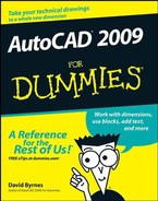
With knowledge of your industry's common drawing scales, you can choose a provisional scale based on what you're depicting. But you won't know for sure whether that scale works until you compare it with the size of the paper that you want to use for plotting your drawing. Here again, most industries use a small range of standard sheet sizes. Three common sets of sizes exist, as shown in Figure 4-2 and Table 4-2:
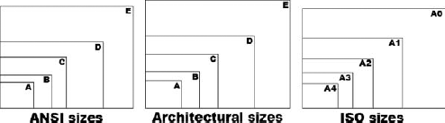
Table 4-2. Common Plot Sheet Sizes
Sheet Size | Dimensions | Comment |
|---|---|---|
ANSI E | 34 × 44" | |
ANSI D | 22 × 34" | E sheet folded in half |
ANSI C | 17 × 22" | D sheet folded in half |
ANSI B | 11 × 17" | C sheet folded in half |
ANSI A | 8 1/2 × 11" | B sheet folded in half |
Architectural Large E | 36 × 48" | |
Architectural E | 30 × 42" | |
Architectural D | 24 × 36" | Large E sheet folded in half |
Architectural C | 18 × 24" | D sheet folded in half |
Architectural B | 12 × 18" | C sheet folded in half |
Architectural A | 9 × 12" | B sheet folded in half |
ISO A0 | 841 × 1189 mm | |
ISO A1 | 594 × 841 mm | A0 sheet folded in half |
ISO A2 | 420 × 594 mm | A1 sheet folded in half |
ISO A3 | 297 × 420 mm | A2 sheet folded in half |
ISO A4 | 210 × 297 mm | A3 sheet folded in half |
You select a particular set of sheet sizes based on the common practices in your industry. You then narrow down your choice based on the area required by what you're going to draw. For example, most imperial-units architectural plans are plotted on Architectural D- or E-size sheets, and most metric architectural plans go on ISO A1 or A0 sheets.
If you know the desired sheet size and drawing scale factor, you can calculate the available drawing area easily. Simply multiply each of the sheet's dimensions by the drawing scale factor. For example, if you choose an 11-×-17-inch sheet and a drawing scale factor of 96 (corresponding to a plot scale of 1/8″ = 1′−0″), you multiply 17 times 96 and 11 times 96 to get an available drawing area of 1,632 inches × 1,056 inches (or 136 feet × 88 feet). If your sheet size is in inches but your drawing scale is in millimeters, you need to multiply by an additional 25.4 to convert from inches to millimeters. For example, with an 11-×-17-inch sheet and a scale of 1:200 (drawing scale factor = 200), you multiply 17 times 200 times 25.4 and 11 times 200 times 25.4 to get 86,360 × 55,880 mm or 86.36 × 55.88 m — not quite big enough for a football field (American or European football).
Conversely, if you know the sheet size that you're going to use and the real-world size of what you're going to draw, and you want to find out the largest plot scale you can use, you have to divide, not multiply. Divide the needed real-world drawing area's length and width by the sheet's dimensions. Take the larger number — either the length result or the width result — and round up to the nearest real drawing scale factor (that is, one that's commonly used in your industry). For example, suppose you want to draw a 60-×-40-foot (or 720-×-480-inch) floor plan and print it on 11-×-17-inch paper. You divide 720 by 17 and 480 by 11 to get 42.35 and 43.64, respectively. The larger number, 43.64, corresponds in this example to the short dimension of the house and the paper. The nearest larger common architectural drawing scale factor is 48 (corresponding to 1/4″ = 1′−0″), which leaves a little room for the plotting margin and title block.
The Cheat Sheet at the front of this book includes two tables that list the available drawing areas for a range of sheet sizes and drawing scales. Those tables can help you decide on an appropriate paper size and drawing scale; revert to the calculation method for situations that the tables don't cover. If you don't keep a favorite old calculator on your physical desktop, don't despair: AutoCAD 2009 has one lurking on the Ribbon. Click the Tools tab and look for the QuickCalc button in the Inquiry panel. (Hint: It looks like a calculator, and you speed demons can toggle QuickCalc off and on with the Ctrl+8 key combo!)
Warning
When you select a sheet size and drawing scale, always leave some extra room for the following two reasons:
Margin allowance: Most plotters and printers can't print all the way to the edge of the sheet — they require a small margin. For example, my trusty old Hewlett-Packard LaserJet 4050 has a printable area of about 8.0 × 10.7 inches on an 8.5-×-11-inch ANSI A-size (letter-size) sheet. (You can find this information in the Plot dialog box, as described in Chapter 16.) If you're a stickler for precision, you can use the printable area instead of the physical sheet area in the calculations described earlier in this section.
Annotations: Most drawings require some annotations — text, grid bubbles, and so on — outside the objects you're drawing, plus a title block surrounding the objects and annotations. If you don't leave some room for the annotations and title block, you'll end up having to cram things together too much or change to a different sheet size. Either way, you'll be slowed down later in the project, when you can least afford it.
Tip
Some industries deal with the "sheet-is-too-small/drawing-scale-is-too-large" problem by breaking drawings up onto multiple plotted sheets. You might consider doing the same.
Tip
Don't be afraid to start with real paper. Experienced drafters often make a quick, throwaway, pencil-and-paper sketch indicating the size of the sheet of paper you intend to plot on, a sketch of the title block, and a very rough, schematic sketch of the thing you're going to draw. It helps to scribble down the dimensions of the sheet, the main title block areas, and the major objects to be drawn. By sketching on paper first, you'll often catch scale or sheet size problems before you set up a drawing, when repairs take only a few minutes — whereas after you've created the drawing, fixing the problem can take hours.
The next decision to make is what kind of border your drawing deserves. The options include a full-blown title block, a simple rectangle, or nothing at all around your drawing. If you need a title block, do you have one, can you borrow an existing one, or will you need to draw one from scratch? Although you can draw title block geometry in an individual drawing, you'll save time by reusing the same title block for multiple drawings. Your company may already have a standard title block drawing ready to use, or someone else who's working on your project may have created one for the project.
The right way to draw a title block is in a separate DWG file at its normal plotted size (for example, 36 inches long by 24 inches high for an architectural D-size title block, or 841 mm long by 594 mm high for an ISO A1-size version). You then insert or xref the title block drawing into each sheet drawing. Chapters 17 and 18 describe how to insert and xref separate DWG files.
When you start in either the 2D Drafting & Annotation workspace or the old AutoCAD Classic workspace, AutoCAD creates a new, blank drawing configured for 2D drafting. Depending on where you live (your country, not your street address!) and the dominant system of measure used there, AutoCAD will base this new drawing on one of two default template drawings: acad.dwt for the imperial system of measure, as used in the United States or acadiso.dwt for the metric system, used throughout the rest of the galaxy. (In AutoCAD LT, the two default templates are named acadlt.dwt and acadltiso.dwt.) When you explicitly create a new drawing from within AutoCAD, the Select Template dialog box, shown in Figure 4-3, appears by default so that you can choose a template on which to base your new drawing.
You may be familiar with the Microsoft Word or Excel template documents, and AutoCAD template drawings work pretty much the same way — because Autodesk stole the idea from them (encouraged, of course, by Microsoft).
A template is simply a drawing whose name ends in the letters DWT, which you use as the starting point for another drawing. When you create a new drawing from a template, AutoCAD makes a copy of the template file and opens the copy in a new drawing editor window. The first time you save the file, you're prompted for a new filename to save to; the original template file stays unchanged.
Using a suitable template can save you time and worry because many of the setup options are already set correctly for you. You know the drawing will print correctly; you just have to worry about getting the geometry and text right. Of course, all this optimism assumes that the person who set up the template knew what he or she was doing.
The stock templates that come with AutoCAD are okay as a starting point, but you'll need to modify them to suit your purposes or create your own from scratch. In particular, the stock AutoCAD templates are probably not set up for the scales that you'll want to use. The instructions in the rest of this chapter tell you how to specify scale-dependent setup information.
So the only problems with templates are creating good ones and then later finding the right one to use when you need it. Later in this chapter, in the "Making Templates Your Own" section, I show you how to create templates from your own setup drawings. Here I show you how to use an already created template, such as one of the templates that comes with AutoCAD 2009 or from one of your CAD-savvy colleagues. If you're lucky, someone in your office has created suitable templates that you can use to get going quickly.
Follow these steps to create a new drawing from a template drawing:
Run the NEW command by pressing Ctrl+N or opening the Menu Browser and choosing File

The Select Template dialog box appears.
Warning
The first button on the Quick Access toolbar runs the QNEW (Quick NEW) command instead of the ordinary NEW command. If you or someone else has changed the Default Template File Name for QNEW in the Options dialog box, QNEW will not open the Select template dialog box but will instead simply present you with a new, blank drawing — possibly not the one you wanted. You can take advantage of QNEW though — for information about how, see the "Making Templates Your Own" section at the end of this chapter.
Click the name of the template that you want to use as the starting point for your new drawing and click the Open button.
A new drawing window with a temporary name, such as
Drawing2.dwg, appears. (The template you opened remains unchanged on your hard disk.)Depending on which template you choose, your new drawing may open in a paper space layout, not in model space. If that's the case, click the Model button on the status bar before changing the settings described in the next section, "Making the Most of Model Space." (If you're working in the AutoCAD Classic workspace, click the Model tab at the lower-left edge of the drawing area.) I describe how to set up and take advantage of paper space layouts in Chapter 5.
Press Ctrl+S and save the file under a new name.
Take the time to save the drawing to the appropriate name and location now.
Make needed changes.
With most of the templates that come with AutoCAD, you need to consider changing the units, limits, grid and snap settings, linetype scale, and dimension scale. See the next section, "Making the Most of Model Space," for instructions.
Save the drawing again.
If you'll need other drawings in the future similar to the current one, consider saving your modified template as a template in its own right. See the next section, "Making Templates Your Own."
Tip
A few of the remaining templates that come with AutoCAD include title blocks for various sizes of sheets. In addition, most templates come in two versions — one for people who use color-dependent plot styles and one for people who use named plot styles. You probably want the color-dependent versions. (Chapter 16 describes the two kinds of plot styles and why you probably want the color-dependent variety.) I warned you that this drawing setup stuff would be complicated!
After you've decided on drawing scale and sheet size, you're ready to set up your drawing. Most drawings require a two-part setup:
Set up model space, where you'll create most of your drawing.
Create one or more paper space layouts for plotting.
As explained in Chapter 2, model space is the infinitely large, three-dimensional environment in which you create the 'real' objects you're drawing. You can perform model space setup as described in this section. Chapter 5 introduces you to setting up your paper space layouts.
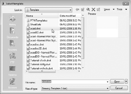
First, you should set the linear and angular units that you want to use in your new drawing. The following procedure describes how:
Choose Format
The Drawing Units dialog box appears, as shown in Figure 4-4.
Choose a linear unit type from the Length Type drop-down list.
Choose the type of unit representation that's appropriate for your work. Engineering and Architectural units are displayed in feet and inches; the other types of units aren't tied to any particular unit of measurement. You decide whether each unit represents a millimeter, centimeter, meter, inch, foot, or something else. Your choice is much simpler if you're working in metric: Choose Decimal units.
Tip
AutoCAD can think in inches! If you're using Engineering or Architectural units (feet and inches), AutoCAD understands any distance or coordinate you enter as that many inches. You use the ' (apostrophe) character on your keyboard to indicate a number in feet instead of inches.
From the Length Precision drop-down list, choose the level of precision you want when AutoCAD displays coordinates and linear measurements.
The precision setting controls how precisely AutoCAD displays coordinates, distances, and prompts in some dialog boxes. For example, the Coordinates section of the status bar displays the current coordinates of the crosshairs using the current precision.
Note
The linear and angular precision settings affect AutoCAD's display of coordinates, distances, and angles on the status bar, in dialog boxes, and in the command window and dynamic input tooltip areas. For drawings stored as DWG files, AutoCAD always uses maximum precision to store the locations and sizes of all objects that you draw. In addition, AutoCAD provides separate settings for controlling the precision of dimension text — see Chapter 14 for details.
Choose an angular unit type from the Angle Type drop-down list.
Decimal Degrees and Deg/Min/Sec are the most common choices.
The Clockwise check box and the Direction button provide additional angle measurement options, but you'll rarely need to change the default settings: Measure angles counterclockwise and use east as the 0 degree direction.
From the Angle Precision drop-down list, choose the degree of precision you want when AutoCAD displays angular measurements.
In the Insertion Scale area, choose the units of measurement for this drawing.
Choose your base unit for this drawing — that is, the real-world distance represented by one AutoCAD unit.
Note
The AutoCAD 2009 Drawing Units dialog box includes a Lighting area where you specify the units type to be used to measure the intensity of photometric lights. That's a fairly advanced 3D feature that I don't cover in this book. If you want more information, visit the online help.
Click OK to exit the dialog box and save your settings.
The next model space setup task is to set your drawing's limits. Well, you wouldn't want it staying out all night and hanging out with just anybody, would you? The limits represent the rectangular working area that you'll draw on, which usually corresponds to the paper size. Setting limits correctly gives you the following advantages:
Showing the grid: If you use default settings, when you turn on the grid (described in the following section), the grid appears within the rectangular limits area. With the grid on, the grid settings at their defaults, and the limits set correctly, you see the working area that corresponds to what you'll eventually be plotting, so you won't accidentally sail off the edge of your paper.
Using ZOOM All: The ZOOM command's All option zooms to the greater of the limits or the drawing extents. (The extents of a drawing consist of a rectangular area just large enough to include all the objects in the drawing.) When you set limits properly and color within the lines, ZOOM All gives you a quick way to zoom to your working area.
Plotting: If you plot from model space, you can choose to plot the area defined by the drawing limits. This option gives you a quick, reliable way to plot your drawing, but only if you've set limits correctly!
Tip
Many CAD drafters don't set limits properly in their drawings. After you read this section, you can tell them — in a nice way, of course — why they should and how.
Note
You can start the LIMITS command from the menu, but all subsequent action takes place in the command window or the dynamic input tooltip; despite the importance of the topic, AutoCAD has no dialog box for setting limits.
The following procedure shows you how to set your drawing limits:
Choose Format
AutoCAD prompts you, with a dynamic input tooltip if DYN mode is enabled and in the command window, to reset the model space limits:
Command: '_limits
Reset Model space limits:
Specify lower left corner or [ON/OFF] <0.0000,0.0000>:
The value at the end of the last line of the command prompt is the default value for the lower-left corner of the drawing limits. It appears according to the units and precision that you selected in the Drawing Units dialog box — for example, 0′−0″ if you selected Architectural units with precision to the nearest inch.
Type the coordinates of the lower-left corner of the limits you want to use and press Enter.
The usual value to enter at this point is 0,0. (Type a zero, a comma, and then another zero, with no spaces.) You can just press Enter to accept the default value.
Warning
Regardless of what you see in the dynamic input tooltip, when you press Enter to accept a default value, the value that will be accepted is the one that shows at the command prompt. Make sure you know where you're entering your values, or you could end up with some pretty funky errors.
AutoCAD now prompts you for the upper-right corner of the limits:
Specify upper right corner <12.0000,9.0000>:
The initial units offered by AutoCAD correspond to an Architectural A- size sheet of paper in landscape orientation. (Almost no one uses Architectural A-size paper; here's a classic example of a programmer choosing a silly default that no one has bothered to change in 25 years!)
If you live in a metric-dominant location, the second prompt will read:
Specify upper right corner <420.0000,297.0000>:
These numbers correspond to an ISO A3-size sheet (much more up to date than those silly, old-fashioned imperial settings!).
Type the coordinates of the upper-right corner of the limits you want to use and press Enter.
You calculate the usual setting for the limit's upper-right corner by multiplying the paper dimensions by the drawing scale factor. For example, if you're setting up a 1/8″ = 1′−0″ drawing (drawing scale factor = 96) to be plotted on a 24-×-36-inch sheet in landscape orientation, the upper-right corner of the limits should be 36 inches times 96, 24 inches times 96. Okay, pencils down. The correct answer is 3456,2304 (or 288 feet, 192 feet).
Tip
Alternatively, you can cheat when specifying limits and read the limits from the tables on the Cheat Sheet in the front of this book.
If you have the grid turned on, AutoCAD by default redisplays it in the new limits area after you press Enter.
Warning
If you're using Architectural or Engineering units and you want to enter measurements in feet and not inches, you must add the foot designator after the number, such as 6'; otherwise, AutoCAD assumes that you mean inches. If you're using Decimal units or one of the other "unitless" types, AutoCAD won't accept the footmark as input.
Open the Menu Browser and choose View
AutoCAD zooms to the new limits.
AutoCAD's grid is a set of evenly spaced dots that serve as a visual distance reference. (As I describe in the preceding section, "Telling your drawing its limits," the grid also indicates how far the drawing limits extend.) AutoCAD's snap feature creates a set of evenly spaced, invisible hot spots, which make the crosshairs move in nice, even increments. Both grid and snap are like the intersection points of the lines on a piece of grid paper, but the grid is simply a visual reference, whereas snap constrains the points that you can pick with the mouse. You can — and usually will — set the grid and snap spacing to different distances.
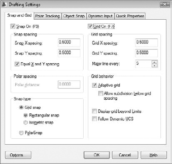
Set the grid and the snap intervals in the Drafting Settings dialog box by following these steps:
Right-click the Snap or Grid button on the status bar and choose Settings.
The Drafting Settings dialog box appears with the Snap and Grid tab selected, as shown in Figure 4-5.
The Snap and Grid tab has five sections, but the Snap and Grid areas within that tab are all you need to worry about for most 2D drafting work.
Select the Snap On check box to turn on snap.
This action enables default snaps half a unit apart.
Note
You can also click the Snap Mode button on the status bar to toggle snap on and off; the same goes for the Grid Display button and the grid setting.
Enter the snap interval you want in the Snap X Spacing box.
Use the information in the sections preceding this procedure to decide on a reasonable snap spacing.
Tip
If the Equal X and Y Spacing check box is selected, the Y spacing automatically changes to equal the X spacing, which is almost always what you want.
Select the Grid On check box to turn on the grid.
Enter the desired grid spacing in the Grid X Spacing box.
Use the information in the sections preceding this procedure to decide on a reasonable grid spacing.
Just like with snap spacing, if the Equal X and Y Spacing check box is selected, the Y spacing automatically changes to equal the X spacing. Again, you usually want to leave it that way.
Note
X measures horizontal distance; Y measures vertical distance. The AutoCAD drawing area normally shows an X and Y icon in case you forget.
Specify additional grid display options in the Grid behavior area.
If you select the Allow Adaptive Grid check box, AutoCAD changes the density or spacing of the grid dots as you zoom in and out. If you also select Allow Subdivision Below Grid Spacing, the spacing can go lower than what you've set, and it may go higher if you're zoomed a long way out of your drawing. (If it didn't, you couldn't see your drawing for the grid dots!)
Selecting Display Grid Beyond Limits allows the grid to display over the entire graphics area, no matter how far you're zoomed out. Clearing this check box makes AutoCAD behave the way it's always behaved — that is, the grid is displayed only in the area defined by the drawing limits.
Tip
I recommend you leave this box deselected as an effective way to tell whether you're drawing beyond your drawing limits. What's the point of setting limits if you don't know where they are?
Note
The Follow Dynamic UCS option (not available in AutoCAD LT) is a 3D-specific feature that changes your drawing plane as you mouse over 3D objects. I don't cover Dynamic UCS or 3D modeling in this book.
Click OK to close the Drafting Settings dialog box.
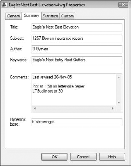
You should do one last bit of bookkeeping before you're finished with model space drawing setup: Enter summary information in the Drawing Properties dialog box, as shown in Figure 4-6. Choose File
Note
Don't confuse drawing properties (which are really file properties) with your drawing's object properties — they're different things. The properties you enter here can help you or someone you love when they open your drawing and wonder how you set it up. Object properties are a big enough topic to merit their own chapter — see Chapter 6.
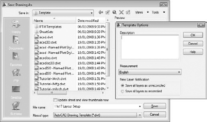
You can create a template from any DWG file by using the Save As dialog box. Follow these steps to save your drawing as a template:
Choose File
The Save Drawing As dialog box appears, as shown in Figure 4-7.
From the Files of Type drop-down list, choose AutoCAD Drawing Template (*.dwt) or AutoCAD LT Drawing Template (*.dwt).
Navigate to the folder where you want to store the drawing.
AutoCAD 2009's default folder for template drawings is called Template and is buried deep in the bowels of your Windows user profile. Save your templates there if you want them to appear in AutoCAD's Select Template list. You can save your templates in another folder, but if you want to use them later, you have to navigate to that folder each time to use them. See the Technical Stuff paragraph that follows this procedure for additional suggestions.
Enter a name for the drawing template in the File Name text box and click Save.
A dialog box for the template description and units appears.
Specify the template's measurement units (English or Metric) in the drop-down list.
Enter the key info now — you can't do it later unless you save the template to a different name. Don't bother filling in the Description field; AutoCAD doesn't display it in the Select Template dialog box.
Click OK to save the file.
To save your drawing as a regular drawing, open the Menu Browser and choose File
The Save Drawing As dialog box appears again.
From the Files of Type drop-down list, choose AutoCAD 2007 Drawing (*.dwg).
AutoCAD 2009 uses the AutoCAD 2007 DWG file format. Choose the AutoCAD LT equivalent, if that's your version. Choose an earlier version if you want to be able to open your drawing in AutoCAD 2006 or previous.
Navigate to the folder where you want to store the drawing.
Use a different folder from the one with your template drawings.
Enter the name of the drawing in the File Name text box and click Save.
The file is saved. Now, when you save it in the future, the regular file, not the template file, gets updated.
Tip
The AutoCAD QNEW (Quick NEW) command, when properly configured, can bypass the Select Template dialog box and create a new drawing from your favorite template. The first button on the Quick Access toolbar — the button with the plain white sheet of paper — runs the newer QNEW command instead of the older NEW command.
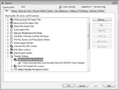
To put the Quick into QNEW, though, you have to tell AutoCAD which default template to use: From the Menu Browser or the menu bar, choose Tools
Note
AutoCAD 2009 stores template drawings and many other support files under your Windows user folder. To discover where your template folder is hiding, open the Menu Browser (or the use the classic menu bar) and choose Tools
Tip
You don't have to keep your template files where that nice Mister Gates tells you. Create a folder that you can find easily (for example, C:Acad-templates or F:Acad-custom emplates on a network drive), put the templates that you actually use there, and change the Drawing Template File Location setting so that it points to your new template folder.