Editing objects is the flip side of creating them, and in AutoCAD, you spend a lot of time editing — far more than drawing objects from scratch. That's partly because the design and drafting process is by its nature repetitive and also because AutoCAD makes it easy to edit objects cleanly.
Note
When you edit objects in AutoCAD, you need to be just as concerned about specifying precise locations and distances as you are when you originally create the objects. Make sure that you're familiar with the precision techniques described in Chapter 7 before you apply the editing techniques from this chapter to real drawings.
AutoCAD offers three styles of editing:
Command-first editing
Selection-first editing
Direct object manipulation (grip editing)
Tip
AutoCAD refers to command-first editing as verb-noun editing and to selection-first editing as noun-verb editing. When you see this terminology — for example, in the Options dialog box or the online help system — don't worry, you haven't dropped back into your fifth-grade English class!
With command-first editing, you start a command and then select the objects on which the command works. This style of editing may seem backward to you at first unless you're a longtime AutoCAD user. Command-first editing works well for power users who are in a hurry and who are willing to memorize most of the commands they need to do their work. It's also the only way to use some of the editing commands (such as FILLET and BREAK). It's no surprise that command-first editing is the classic editing style in AutoCAD, and the one method with which you need to be most comfortable.
In selection-first editing, you perform the same steps — in the same order — as in most Windows applications: Select the object first and then choose the command. Selection-first editing tends to be easier to master and makes AutoCAD more approachable for new and occasional users.
With direct object manipulation, you perform common editing operations by using the mouse to grab the selected object and perform an action on it, such as moving all or part of it to a different place in the drawing. No named command is involved; the act of moving the mouse and clicking the mouse buttons in certain ways causes the editing changes to happen. AutoCAD supports direct object manipulation through a powerful but somewhat complicated technique called grip editing. Grips are the little square handles that appear on an object when you select it. You can use the grips to stretch, move, copy, rotate, scale, or otherwise edit the object.
This book emphasizes command-first editing, but I also discuss grip editing at the end of this chapter. AutoCAD in its heart of hearts is a command-first program. In fact, it started out offering only command-first editing and later added selection-first methods; AutoCAD 2009 inherits this ancestral trait. I stress command-first editing for the following reasons:
It's the editing style that's been in AutoCAD the longest and the one with which experienced AutoCAD users are most familiar.
It works consistently with all editing commands — some editing commands remain command-first only.
It provides added object selection flexibility, which is useful when you work on complicated, busy drawings.
After you know how to do command-first editing, you can simply reverse the order of many editing operations to do them selection-first style instead. But if you don't get familiar with command-first editing in the beginning, you'll be bewildered by a few useful AutoCAD commands that work only in the command-first style; commands such as these ignore any already selected objects and prompt you to select objects.
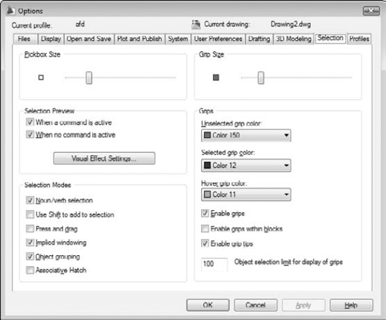
Much of the information in the rest of this book assumes that you're using the default AutoCAD selection settings. If object selection or grip editing works differently than I describe in this chapter, choose Tools
Tip
For information on what these options do, hover the mouse pointer over an option to display a tooltip with information from the online help.
Part of AutoCAD's editing flexibility comes from its object selection flexibility. For example, command-first editing offers 16 selection modes! (I describe the most useful ones in this chapter.) Don't worry, though; you can get by most of the time with three selection modes, each of which I describe in this section:
Selecting a single object by picking it
Selecting multiple objects by enclosing them in a window selection box
Selecting multiple objects by enclosing them in a crossing selection box
The most obvious way to select objects is to pick (by clicking) them one at a time. One or more objects that are selected and ready for editing are called a selection set. You can build up a selection set cumulatively with this pick-one-object-at-a-time selection mode, but this cumulative convention may be different from what you're used to. In most Windows programs, if you select one object and then another, the first object is deselected, and the second one selected; only the object you select last remains selected. In AutoCAD, all the objects you select, one at a time, remain selected and are added to the selection set, no matter how many objects you pick. (You can change this behavior to make AutoCAD work like other Windows programs by turning on the Use Shift to Add to Selection option on the Option dialog box's Selection tab, but I suggest that you don't change it.) Most editing commands affect the entire group of selected objects.
Selecting objects one at a time works great when you want to edit a small number of objects, but many CAD editing tasks involve editing lots of objects. Do you really want to pick 132 lines, arcs, and circles, one at a time?
Like most Windows graphics programs, AutoCAD provides a selection window feature for grabbing a bunch of objects in a rectangular area. As you may guess by now, the AutoCAD version of this feature is a bit more powerful than the similar feature in other Windows graphics programs and, therefore, is slightly confusing at first. AutoCAD calls its version implied windowing. Here's how you use it.
If you click a blank area of the drawing — that is, not on an object — you're implying to AutoCAD that you want to specify a selection window, or box. If you move the crosshairs to the right before picking the other corner of the selection box, you're further implying that you want to select all objects that reside completely within the selection box. If you move the crosshairs to the left before picking the other corner of the selection box, you're implying that you want to select all objects that reside completely or partially within the selection box.
The AutoCAD terminology for these two kinds of selection boxes gets a little confusing:
The move-to-the-right, only-select-objects-completely-within-the-box mode is called window object selection.
The move-to-the-left, select-objects-completely-or-partially-within-the-box mode is called crossing object selection.
Fortunately, AutoCAD gives you visual cues that there's a difference. As you move to the right, the window box appears as a rectangle with blue fill and a solid border. As you move to the left, the crossing box appears as a rectangle with green fill and a dashed border.
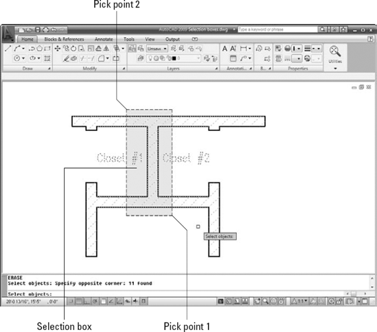
Figures 10-2 and 10-3 show a window box and a crossing box in action.

Figure 10-2. A window selection box, drawn left to right, selects only objects completely within the box.
You can mix and match selecting individual objects, specifying a window box, and specifying a crossing box. Each selection adds to the current selection set, allowing you to build up an enormously complicated selection of objects and then operate on them with one or more editing commands.
Tip
You can press the Shift key in combination with any of the three standard selection modes — single object, window box, and crossing box — to remove already-selected objects from the selection set. This feature is especially useful when you're building a selection set in a crowded drawing; you can select a big batch of objects by using Window or Crossing, and then hold down the Shift key while selecting to remove the objects that you want to exclude from the editing operation.
When you edit in command-first mode, you have all the selection options described in the previous section — single object, window box, and crossing box — plus a slew of others. If you type ? and press Enter at any Select objects prompt, AutoCAD lists all the selection options at the command line:
Window/Last/Crossing/BOX/ALL/Fence/WPolygon/CPolygon/
       Group/Add/Remove/Multiple/Previous/Undo/AUto/
       SIngle/SUbobject/Object
Note
Subobject and Object apply specifically to 3D solids and are therefore not available in AutoCAD LT. In any event, this book doesn't cover 3D construction.
Table 10-1 summarizes the most useful command-first selection options.
Table 10-1. Some Useful Command-First Selection Options
Description | |
|---|---|
Window | All objects completely within a rectangle that you specify by picking two points |
Crossing | All objects within or crossing a rectangle that you specify by picking two points |
WPolygon | All objects completely within a polygonal area whose corners you specify by picking points |
CPolygon | All objects within or crossing a polygonal area whose corners you specify by picking points |
Fence | All objects touching an imaginary polyline whose vertices you specify by picking points |
Last | The last object you drew that's still visible in the drawing area |
Previous | The previous selection set that you specified |
ALL | All objects on layers that aren't frozen or locked and that are in the current space (model space or paper space) |
To use any of the command-first selection options at the Select objects prompt, type the uppercase letters indicated in Table 10-1 that correspond to the desired option and press Enter. After you're finished selecting objects, you must press Enter again to tell AutoCAD that you've finished selecting objects and want to start the editing operation.
Note
After you're finished selecting objects, you must press Enter again to tell AutoCAD that you've finished selecting objects and want to start the editing operation. Say ...is there an echo in here? As a matter of fact, I am repeating myself. One of the things that most new AutoCAD users find hardest to remember is the necessity of pressing Enter after you finish selecting objects.
Tip
AutoCAD's Selection preview features remove any doubt about which objects you're selecting. Rollover highlighting displays individual objects with a thick, dashed lineweight as you move the crosshairs over them. Area selection displays a transparent, colored highlight over multiple selections using window and crossing options. You can enable and disable both features on the Selection tab of the Options dialog box (refer to Figure 10-1).
The following example demonstrates how to use the ERASE command in command-first mode with several different selection options. The selection techniques used in this example apply to most AutoCAD editing commands.
Click the Home tab on the Ribbon.
The most frequently used AutoCAD commands are found on the Ribbon's Home tab.
Press Esc to make sure that no command is active and no objects are selected.
Warning
If any objects are selected when you start an editing command, the command, in most cases, will operate on those objects (selection-first editing) instead of prompting you to select objects (command-first editing). For the reasons that I describe earlier in this chapter, you should use the command-first editing style until you're thoroughly familiar with it. Later, you can experiment with selection-first editing if you like. (Just reverse the sequence of commanding and selecting that I describe in this chapter.)

AutoCAD displays the
Select objectsprompt at the command line and, if dynamic input is enabled on the status bar, the dynamic input tooltip.Select two or three individual objects by clicking each one.
AutoCAD adds each object to the selection set. All the objects you select remain highlighted, and AutoCAD continues to display the
Select objectsprompt.Specify a window selection box that completely encloses several objects.
Move the crosshairs to a point below and to the left of the objects, click, release the mouse button, move the crosshairs above and to the right of the objects, and click again.
All objects that are completely within the box are selected.
Specify a crossing selection box that completely encloses a few objects and cuts through several others.
Move the crosshairs to a point below and to the right of some of the objects, click, release the mouse button, move the crosshairs above and to the left of some of the objects, and click and release again.
All objects that are completely within or cross through the box are selected. AutoCAD continues to display the
Select objectsprompt.Type WP and press Enter to activate the WPolygon selection option.
AutoCAD prompts you to pick points that define the selection polygon.
Pick a series of points and press Enter.
Figure 10-4 shows an example. After you press Enter, AutoCAD selects all objects that are completely within the polygon. AutoCAD continues to display the
Select objectsprompt until ...Press Enter to end object selection.
AutoCAD erases all the selected objects and returns to an empty command prompt.

Notice how you were able to use a combination of object selection methods to build up a selection set and then press Enter to execute the command on the selected objects. Most AutoCAD editing commands work this way in command-first mode.
Tip
If, after erasing a selection set, you immediately realize that you didn't really mean to do away with so many objects, you can use the Undo button on the Quick Access toolbar (or the AutoCAD Classic Standard toolbar) to restore all of them. But AutoCAD has one additional unerase trick up its sleeve — the aptly named OOPS command. When you type OOPS and press Enter, AutoCAD restores the last selection set that you erased — even if you've run other commands after ERASE.
Tip
The ERASE command is not the only way to remove unwanted objects from your drawing. If you're using the classic menu bar, you can choose Edit
Although command-first editing is the most flexible and widespread editing style in AutoCAD, it's not the only way. Grip editing is a useful adjunct to command-first editing, especially when you want to modify just one or two objects. You may have encountered grip editing when using other kinds of graphics programs. But even if you're an experienced user of other graphics programs, you've never seen grips used in quite the way that AutoCAD uses them.
Tip
Anything that you can do with grip editing can be done with command-first editing as well. In some situations, grip editing is a little more efficient or convenient than command-first editing, but command-first editing always gets the job done. If you master only one style of editing, make it command-first style. In other words, feel free to skip this section — at least until you're comfortable with command-first editing.
Grips are those little square or triangular handles that appear on an object after you select it.
In their simplest guise, AutoCAD grips work similarly to the little squares on graphical objects in other Windows programs. But in AutoCAD, instead of clicking and dragging a grip, you must click, release the mouse button, move the crosshairs, and click again at the new location. (By separating the selection of beginning and ending points into two different operations, AutoCAD allows you to use different techniques — such as different object snap modes — to select each point.)
AutoCAD grips are, for sophisticated users, better than the grips found in most other programs because you can do so much more with them. You can, for example, use AutoCAD grips to move, stretch, or copy an object. You also can use them to rotate an object, scale it to a different size, or mirror an object — that is, create one or more reversed copies. Grips also act as visible object snaps, or little magnets that attract the crosshairs.
The following sections cover in detail the five grip-editing modes: STRETCH, MOVE, ROTATE, SCALE, and MIRROR. Follow these steps to explore the grip-editing modes:
Press Esc to make sure that no command is active and no objects are selected, and then click Quick Properties on the status bar to turn off the Quick Properties panel.
AutoCAD displays a blank command prompt — that is, no command is currently active.
Click an object on-screen to select it and display its grips.
Grips — solid blue squares on the selected object — appear at various points on the object. Note that the AutoCAD command prompt remains blank; you haven't started a command or grip-editing operation yet.
Click another object.
Both the newly selected object and the previously selected object display grips.
Click one of the grips on either object.
The blue square turns to a dark red square. This grip is now hot, or ready for a grip-editing operation. Grip-editing options now appear on the command line. The first option to appear is STRETCH.
Press the spacebar repeatedly to cycle through the five grip-editing options on the command line.
** STRETCH **
Specify stretch point or [Base point/Copy/Undo/eXit]:
** MOVE **
Specify move point or [Base point/Copy/Undo/eXit]:
** ROTATE **
Specify rotation angle or [Base point/Copy/Undo/Reference/eXit]:
** SCALE **
Specify scale factor or [Base point/Copy/Undo/Reference/eXit]:
** MIRROR **
Specify second point or [Base point/Copy/Undo/eXit]:
The grip-editing option displayed on the command line and the dynamic input tooltip changes as you press the spacebar. If you move the crosshairs (without picking) in between each press of the spacebar, the appearance of your selected object changes as you display each option. Choosing STRETCH, for example, causes a stretched version of the object to appear on-screen.
Tip
Pressing the spacebar a bunch of times is a good way to become familiar with the grip-editing modes, but there's a more direct way to choose a particular mode. After you click a grip to make it hot, right-click to display the grip-editing menu. That menu contains all the grip-editing options plus some other choices, as shown in Figure 10-5.
Tip
If dynamic input is enabled, pressing the down-arrow key while cycling through the grip-editing options displays a dynamic menu at the crosshairs from which you can choose options specific to the current grip-editing function.
Press the spacebar until STRETCH (or the option you want) reappears as the grip-editing option.
Move the hot grip in the direction in which you want to stretch (or otherwise manipulate) your object.
AutoCAD dynamically updates the image of the object to show you what the modified object will look like before you click the final location.
Click again to finish the grip-editing operation.
The selected object with the hot grip updates.
Click the same grip that you chose in Step 4 (now in a different location) to make it hot.
This time, move the crosshairs near one of the grips on the other object. When you see the magnetic pull of the grip on the other object, click again to connect the hot grip with the other grip.
The object point represented by the hot grip now coincides exactly with the grip on the other object.
Press Esc to deselect all objects and remove all grips.
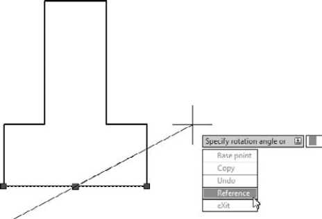
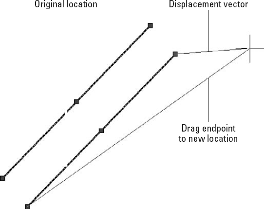
Figure 10-6 shows a hot (dark red) endpoint grip of a line being connected to the cold (blue) endpoint grip of another line. The angled line shows the original position of the line being edited, and the thin vertical line shows the new position. Using a grip in this way as a visible object snap offers the same advantage as using object snap overrides, as described in Chapter 7: It ensures precision by making sure that objects meet exactly.
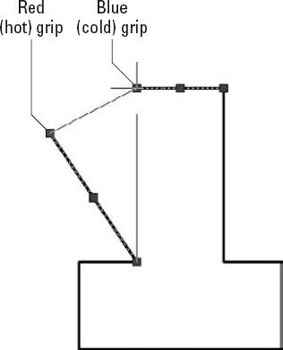
You can experiment with all the grip-editing options to find out how they affect a selected object. Because MOVE and STRETCH are the most useful grip-editing modes, I cover them in more detail.
Back in the days of manual drafting, moving objects was a big pain in the eraser. You had to erase the stuff you wanted to move and redraw the objects in their new location. In the process, you usually ended up erasing parts of other stuff that you didn't want to move and left smudged lines and piles of eraser dust everywhere. CAD does away with all the fuss and muss of moving objects, and AutoCAD grip editing is a great way to make it happen. The following steps describe how to move objects:
Select one or more objects.
Use any combination of the three editing modes — single object, window box, and crossing box — described in the "Grab It" section, earlier in this chapter.
Click one of the grips to make it hot.
At this point in your editing career, it doesn't matter which grip you click. As you become more familiar with grip editing, you'll discover that certain grips serve as better reference points than others for particular editing operations.
Right-click anywhere in the drawing area and choose Move from the crosshairs menu.
Move the crosshairs to a different location and click.
As you move the crosshairs around, AutoCAD displays the tentative new positions for all the objects, just as it does for the regular Move command, as shown previously in Figure 10-6. After you click, the objects assume their new positions.
Press Esc to deselect all objects and remove all grips.
If you were paying attention during the section "A gripping example," earlier in the chapter, you may have noticed while pressing the spacebar that copy was not among the five grip-editing modes. Why not? Because every grip mode includes a copy option (as the command-line prompts show in the "A gripping example" section). In other words, you can STRETCH with copy, MOVE with copy, ROTATE with copy, SCALE with copy, and MIRROR with copy.
The copy option leaves the selected objects in place and does the editing operation on a new copy of the objects.
By far the most common use for the copy option is with the MOVE grip-editing mode. If you think about "MOVE with copy" for about two seconds, you'll realize that it's just a complicated way of saying "copy." The following steps show how to copy objects quickly by using grip editing:
Select one or more objects.
Click any one of the grips to make it hot.
Right-click anywhere in the drawing area and choose Move from the menu.
Right-click again and choose Copy from the menu.
Move the crosshairs to a different location and click.
After you click, new objects appear in the new location.
Move the crosshairs to additional locations and click there if you want to make additional copies.
Press Esc twice — once to end the copying operation and once to deselect all objects and remove all grips.
The STRETCH grip-editing mode works differently from the other modes. By default, it affects only the object with the hot grip on it, not all objects with grips on them. You can override this default behavior by using the Shift key to pick multiple hot grips. Follow these steps to get acquainted with using the STRETCH grip-editing mode to stretch one or more objects:
Make sure that Ortho mode is toggled off on the status bar by clicking the Ortho Mode button until the words
<Ortho off>appear on the command line.Ortho mode forces stretch displacements to be orthogonal — that is, parallel to lines running at 0 and 90 degrees. During real editing tasks, you'll often want to turn on ortho mode, but while you get acquainted with stretching, leaving ortho mode off makes things clearer.
Select several objects, including at least one line.
On one of the lines, click one of the endpoint grips to make it hot.
All the objects remain selected, but as you move the crosshairs, only the line with the hot grip changes. Figure 10-7 shows an example.
Click a new point for the hot endpoint grip.
The line stretches to accommodate the new endpoint location.
On the same line, click the midpoint grip to make it hot.
As you move the crosshairs, the entire line moves. Using the STRETCH grip-editing mode with a line's midpoint "stretches" the entire line to a new location.
Click a new point for the hot midpoint grip.
The line moves to the new midpoint location.
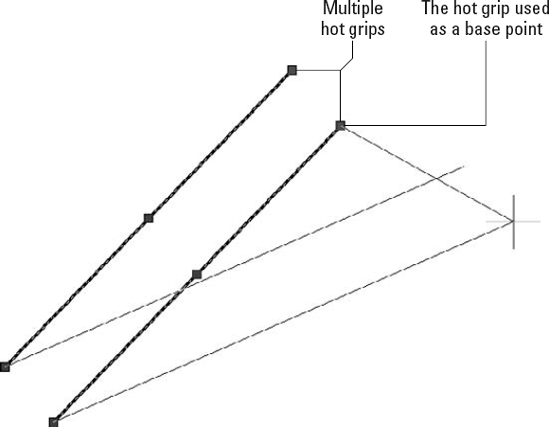
Hold down the Shift key. On one of the lines, click one of the endpoint grips to make it hot.
Still holding down the Shift key, click one of the endpoint grips on a different line to make it hot.
Two grips on two different lines are now hot because you held down the Shift key and then clicked both grips.
Tip
You can create more hot grips by holding down the Shift key and clicking more grips.
Release the Shift key and re-pick any one of the hot grips.
Releasing the Shift key signals that you're finished making grips hot. Re-picking one of the hot grips establishes it as the base point for the stretch operation.
Click a new point for the grip.
All the objects with hot grips stretch based on the displacement of the grip that you clicked in Step 9 (see Figure 10-8).
Turn on ortho mode by clicking its status bar button until the words
<Ortho on>appear on the command line. Repeat Steps 2 through 10 to see the effect of ortho mode on stretching.