Understanding dimension parts and types
Using dimension styles from other drawings
Creating and modifying your own dimension styles
Choosing a dimensioning method
Drawing and modifying annotative dimensions
Editing dimensions
In drafting — either CAD or manual drafting — dimensions are special text labels with attached lines that together clearly indicate the size of something. Although it's theoretically possible to draw all the pieces of each dimension by using AutoCAD commands such as LINE and MTEXT, dimensioning is so common a drafting task that AutoCAD provides special commands for doing the job more efficiently. These dimensioning commands group the parts of each dimension into a convenient, easy-to-edit package. Even better, as you edit an object — by stretching it, for example — AutoCAD automatically updates the measurement displayed in the dimension text label to indicate the object's new size, as shown in Figure 14-1. And perhaps best of all, AutoCAD 2009's annotative dimensions automatically change their size as you change the annotation scale on the model tab or the viewport scale in a layout. I explain the general principles of annotative objects in Chapter 13; in this chapter, I take a closer look at annotative dimensions.
AutoCAD controls the look of dimensions by means of dimension styles, just as it controls the look of text with text styles, and tables with table styles. (AutoCAD also uses text styles to control the appearance of the text in dimensions.) But dimension styles are much more complicated than text styles because dimensions have so many more pieces that you need to control. After you find or create an appropriate dimension style, you use one of several dimensioning commands to draw dimensions that point to the important points on an object (the two endpoints of a line, for example).

Warning
AutoCAD dimensioning is a big, complicated subject. (It's so complicated, in fact, that Autodesk has an especially wise person in charge of dimensioning in AutoCAD — this person is called the dimwit.) Every industry has its own dimensioning conventions, habits, and quirks. As usual, AutoCAD tries to support them all and, in so doing, makes things a bit convoluted for everyone. This chapter covers the essential concepts and commands that you need to know to start drawing dimensions. Be prepared to spend some additional time studying how to create any specialized types of dimensions that your industry uses. Who knows — if you work very hard and practice every day, you too could become an AutoCAD dimwit!
Note
You add dimensions to a drawing after you've drawn at least some of the geometry; otherwise, you won't have much to dimension! Your dimensioning and overall drafting efficiency improve if you add dimensions in batches, rather than draw a line, draw a dimension, draw another line, draw another dimension. . . .
Before digging into the techniques that you use to create dimension styles and dimensions, here's some AutoCAD dimensioning terminology that you need to understand. If you're already familiar with CAD dimensioning lingo, just skim this section and look at the figures in it. Otherwise, read on.
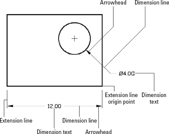
AutoCAD uses the names shown in Figure 14-2 and described in the following list to refer to the parts of each dimension:
Dimension text: Dimension text is usually the number that indicates the actual distance or angle. Dimension text can also include other text information in addition to or instead of the number. For example, you can add a suffix such as
TYP.to indicate that a dimension is typical of several similar configurations, or you can insert a description such asSee Detail 3/A2.Dimension lines: In dimensions that indicate length or distance, the dimension lines go from the dimension text outward, either horizontally, vertically, rotated at a specified angle, or parallel to the object being measured, to indicate the extent of the dimensioned distance. (For other dimension types — for example, the radius and diameter dimensions shown a bit later in Figure 14-3 — the dimension line simply points at the object being dimensioned.) AutoCAD's default dimension style settings center the dimension text vertically and horizontally on the dimension lines as shown in Figure 14-2, but you can change those settings to cause the text to appear in a different location — sitting over an unbroken dimension line as shown previously in Figure 14-1, for example. See the section, "Adjusting style settings," later in this chapter, for instructions.
Arrowheads: The dimension's arrowheads appear at the ends of the dimension lines and clarify the extent of the dimensioned length. AutoCAD's default arrowhead style is the closed, filled type shown in Figure 14-2, but you can choose other symbols, such as tick marks, to indicate the ends of the dimension lines. (Don't get ticked off, but AutoCAD calls the line ending an arrowhead even when, as in the case of a tick mark, it doesn't look like an arrow.)
Extension lines: Extension lines extend outward from the extension line origin points that you select (usually by snapping to points on an object) to the dimension lines. By drafting convention, a small gap usually exists between the extension line origin points and the beginning of the extension lines. You can also make a set of dimensions look tidier by assigning fixed lengths for the extension lines. And if you need to dimension to circles or centerlines, you can assign dash-dot linetypes to either or both extension lines. The extension lines usually extend just beyond where they meet the dimension lines.
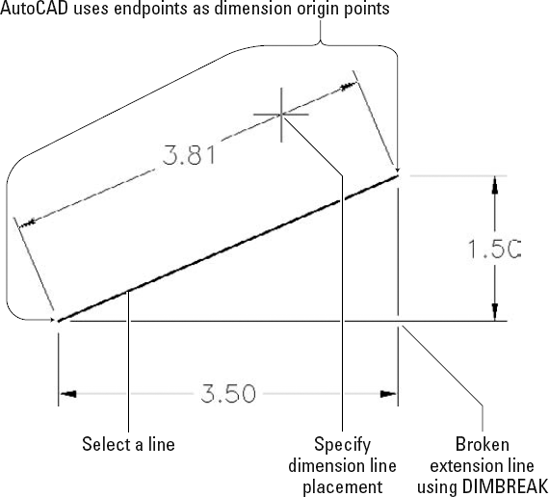
AutoCAD provides several types of dimensions and commands for drawing them. Figure 14-3 shows the most common types, and the following list describes them:
Linear dimensions: A linear dimension measures the linear extent of an object or the linear distance between objects. Most linear dimensions are either horizontal or vertical, but you can draw dimensions that are rotated to other angles, too.
Aligned dimensions: An aligned dimension is similar to a linear dimension, but the dimension line tilts to the same angle as a line drawn through the origin points of its extension lines.
Radial dimensions: A radius dimension calls out the radius of a circle or arc, and a diameter dimension calls out the diameter of a circle or arc. You can position the dimension text inside or outside the curve, as shown in Figure 14-3. If you position the text outside the curve, AutoCAD (by default) draws a little cross at the center of the circle or arc. As shown in Figures 14-2 and 14-3, AutoCAD automatically adds the diameter and radius symbols to the appropriate dimension type.
Angular dimensions: An angular dimension calls out the angular measurement between two lines, the two endpoints of an arc, or two points on a circle. The dimension line appears as an arc that indicates the sweep of the measured angle.

Other types of dimensions and dimension-like annotations you can add to AutoCAD objects include arc length and ordinate dimensions, tolerances, inspection dimensions, and center marks. Look up "dimensions, creating" on the Index tab in the AutoCAD online help system for more information about other less frequently used kinds of dimensions.
By default, AutoCAD groups all the parts of each dimension — the extension lines, dimension lines, arrowheads, and text — into a special associative dimension object. Associative means two things:
The different parts of the dimension function as a single object. When you click any part of the dimension, AutoCAD selects all of its parts.
The dimension is connected to the points on the object that you specified when you drew the dimension. If you change the size of the object (for example, stretch a line), the dimension updates appropriately — the lines and arrows move, and the text changes to reflect the line's new size.
Note
The associative dimensions I'm talking about here first appeared in AutoCAD 2002. Before that, AutoCAD had a more primitive kind of dimensioning. Dimensions were single objects, and they did update if you stretched an object while being very careful to include the dimension itself in the crossing selection for the STRETCH command. Here's where things can get a bit confusing: AutoCAD used to call these old-style, single-object dimensions associative but now calls them non-associative, and what used to be called non-associative dimensions before AutoCAD 2002 are now called exploded dimensions. For more information about how to determine which kind of dimension AutoCAD draws, see the "Controlling and editing dimension associativity" section, later in this chapter.
The Annotate panel on the Ribbon's Home tab provides access to AutoCAD's most frequently used basic dimensioning commands. If you're an AutoCAD Classic workspace user, you'll find them on the classic Dimension menu and Dimension toolbar.
Tip
As much as I like the 2D Drafting & Annotation workspace and the Ribbon, one task where the classic interface just might be more efficient is in dimensioning. The classic Dimension toolbar provides access to more dimension tools than the Ribbon, and it does so while maintaining consistent one-click access to each command. Using the Ribbon, you may find it takes a couple of clicks to get to the command you want. In a Ribbon-based workspace, you can access the classic Dimension toolbar by right-clicking the Quick Access toolbar and choosing Toolbars
Tip
All dimensioning commands have long command names (such as DIMARC, DIMLINEAR, and DIMRADIUS) and corresponding command aliases (such as DAR, DLI, and DRA, respectively) that you can type at the command prompt. If you do lots of dimensioning and don't want to toggle the Dimension toolbar on and off repeatedly, memorize the abbreviated forms of the dimension commands that you use frequently. You can find a list of the long command names on the Contents tab in the AutoCAD online help system. Choose Command Reference
Creating a usable dimension style that gives you the dimension look you want is the biggest challenge in using AutoCAD's dimensioning features. Each drawing contains its own dimension styles, so changes you make to a dimension style in one drawing affect only that drawing. However, after you get the dimension styles right in a drawing, you can use it as a template or starting point for later drawings.
A dimension style (or dimstyle for short) is a collection of drawing settings called dimension variables, which are a special class of the system variables that I describe in Chapter 24.
You can create dimension styles with the new annotative property — the steps to creating both annotative and non-annotative dimension styles are spelled out in the following sections. Although it's possible to change individual non-annotative dimensions to annotative in the Quick Properties panel or the Properties palette, it's far more efficient to assign the annotative property to a dimension style so that all dimensions created in that style will be annotative.
If you're lucky enough to work in an office where someone has set up dimension styles that are appropriate for your industry and project, you can skip the pain and strain of creating your own dimension styles. Bear in mind, however, that since annotative objects were introduced in AutoCAD 2008, dimension styles copied from pre-AutoCAD 2008 drawings are not going to be annotative. If the ready-made dimension style that you need lives in another drawing, you can use the DesignCenter palette to copy it into your drawing. For a refresher on using DesignCenter, see the sections "Using AutoCAD DesignCenter" and "Copying layers between drawings" in Chapter 6 — just substitute "dimension styles."
If you do need to create your own dimension styles or you want to tweak ones that you copied from another drawing, you use the Dimension Style Manager dialog box, shown in Figure 14-4.

Every drawing comes with a default dimension style named Standard (for imperial [feet and inches] drawings) or ISO-25 (for metric drawings). Although you can use and modify the Standard or ISO-25 style, I suggest that you leave them as-is and create your own dimension style(s) for the settings that are appropriate to your work. This approach ensures that you can use the default style as a reference. More important, it avoids a potential naming conflict that can change the way your dimensions look if the current drawing gets inserted into another drawing. (Chapter 17 describes this potential conflict.)
New drawings created in AutoCAD 2009 or AutoCAD LT 2009 using either the imperial template (acad.dwt or acadlt.dwt in AutoCAD LT) or the metric template (acadiso.dwt or acadltiso.dwt in LT) contain two dimension styles. As noted previously, imperial drawings have a style named Standard, and metric drawings sport a style named ISO-25 — what's new is that both have a new style called Annotative. The Annotative style is a clone of Standard or ISO-25 with the single difference being the values of the overall scale factor (also known as the DIMSCALE system variable).
The following steps describe how to create your own dimension style(s):
On the Ribbon's Home tab, click the label of the Annotation panel to open the panel slideout, then click the Dimension Style button. (In the AutoCAD Classic workspace, choose Format

The Dimension Style Manager dialog box appears.
In the Styles list, select the existing dimension style whose settings you want to use as the starting point for the settings of your new style.
For example, select the default dimension style named Standard or ISO-25.
Click the New button to create a new dimension style that's a copy of the existing style.
Enter a New Style Name and select or deselect the Annotative check box. Click Continue.
Select the Annotative check box to create an annotative dimension style, or deselect it for a non-annotative style. Refer to Chapter 13 for more about annotative objects.
The New Dimension Style dialog box appears. (This dialog box is virtually identical to the Modify Dimension Style dialog box shown in Figure 14-5 in the following section.)
Modify dimension settings on any of the seven tabs in the New Dimension Style dialog box.
See the descriptions of these settings in the next section of this chapter.
Click OK to close the New Dimension Style dialog box.
The Dimension Style Manager dialog box reappears.
Click Close.
The Dimension Style Manager dialog box closes and your new dimension style becomes the current dimension style that AutoCAD uses for future dimensions in this drawing.
Draw some dimensions to test your new dimension style.
Warning
Avoid changing existing dimension styles that you didn't create unless you know for sure what they're used for. When you change a dimension style setting, all dimensions that use that style change to reflect the revised setting. Thus, one small dimension variable setting change can affect a large number of existing dimensions! To play it safe, instead of modifying an existing dimension style, create a new style by copying the existing one and modifying the new one.
Note
A further variation on the already convoluted dimension style picture is that you can create dimension substyles (also called style families) — variations of a main style that affect only a particular type of dimension, such as radial or angular. If you open the Dimension Style Manager dialog box and see names of dimension types indented beneath the main dimension style names, be aware that you're dealing with substyles.
After you click New or Modify in the Dimension Style Manager dialog box, AutoCAD displays a tabbed New Dimension Style or Modify Dimension Style dialog box (the two dialog boxes are identical except for the title bar) with a mind-boggling — and potentially drawing-boggling if you're not careful — array of settings. Figure 14-5 shows the settings on the Lines tab, which I've modified from the AutoCAD defaults to conform to one office's drafting standards.
Fortunately, the dimension preview that appears on all tabs — as well as on the main Dimension Style Manager dialog box — immediately shows the results of most setting changes. With the dimension preview and some trial-and-error changing of settings, you can usually home in on an acceptable group of settings. For more information, use the dialog box help feature: Just hover your mouse pointer over the setting that you want to know more about.
Tip
Before you start messing with dimension style settings, it's important to know what you want your dimensions to look like when they're plotted. If you're not sure how it's done in your industry, ask others in your office or profession or look at a plotted drawing that someone in the know represents as being a good example.

The following sections introduce you to the more important tabs in the New Dimension Style and Modify Dimension Style dialog boxes and highlight useful settings. Note that whenever you specify a distance or length setting, you should enter the desired plotted size. For dimensions created with annotative styles, these are the actual paper (plotted) sizes. For dimensions with non-annotative styles, AutoCAD scales all these numbers by the overall scale factor that you enter on the Fit tab.
The settings on the Lines tab and the Symbols and Arrows tab control the basic look and feel of all parts of your dimensions except text. Use these tabs to change the type and size of arrowheads or the display characteristics of the dimension and extension lines.
Use the Text tab to control how your dimension text looks — the text style and height to use (see Chapter 13) and where to place the text with respect to the dimension and extension lines. You'll probably want to change the Text Style setting to something that uses a more pleasing font than the ugly default Txt.shx font, such as the Romans.shx font. The default Text Height is too large for most situations — set it to 1/8″, 3 mm, or another height that makes sense. Figure 14-6 shows one company's standard text settings.

Warning
If you're not opposed to defacing books, get out a bright red marker and put a circle around this warning (unless you borrowed the book from the library, of course). Here goes: You must define the text style that you specify for a dimension style with a height of 0 in the Text Style dialog box. (See Chapter 13 for more information about variable-height and fixed-height text styles.) If you specify a fixed-height text style for a dimension style, the text style's height will override the Text Height setting in the New Dimension Style and Modify Dimension Style dialog boxes. Use a zero-height style to avoid the problem — and bear in mind that using nonzero-height text styles in dimensions is one of the most common mistakes made by new AutoCAD users.
Tip
Industry or company standards usually dictate the size of dimension text. (For example, 1/8″ or 3 mm is common in the architectural industry.) In any case, make sure you pick a height that's not too small to read on your smallest check plot.
The Fit tab includes a bunch of confusing options that control when and where AutoCAD shoves the dimension text if it doesn't quite fit between the dimension lines. The default settings leave AutoCAD in "maximum attempt at being helpful" mode — that is, AutoCAD moves the text, dimension lines, and arrows around automatically so that things don't overlap. If these guesses seem less than satisfactory to you, try the modified settings shown in Figure 14-7: Select the Over Dimension Line, Without Leader radio button under Text Placement and the Draw Dim Line Between Ext Lines check box under Fine Tuning. (You can always move the text yourself by grip editing it, as I describe later in this chapter.)
Tip
Even at its most helpful, AutoCAD sometimes makes a bad first guess about how you want your dimension text and arrows arranged. If you're having problems getting the look you want, don't flip your wig — flip your arrows to the other side of the dimension lines by selecting the dimension, right-clicking, and choosing Flip Arrow from the menu.
Most important, the Fit tab includes the Annotative check box, as shown in Figure 14-7. Using annotative dimensions, as I recommend in this chapter, will make your dimensioning go a lot more smoothly!
Note
Just as with text, as I explain in Chapter 13, you can choose between three different methods for dimensioning your drawings:
You can dimension in model space using annotative dimensions. Assign annotation scales to the dimensions, and they change size as you change scales in the Annotation scales list on the status bar. I think this system has the most to offer both new and experienced users.
You can dimension in model space with non-annotative dimensions. If your drawing includes areas of different scales, you can create multiple dimension styles, one for each scale. This is probably the least convenient method, especially in a drawing with multiple scale views.
You can dimension in paper space using either annotative or non-annotative dimensions. Select the Scale Dimensions to Layout radio button on the Dimension Style Manager's Fit tab and draw dimensions in a paper space layout.

Tip
I recommend that you get comfortable with annotative dimensioning in model space first. If you later want to try dimensioning in paper space, look up "dimensioning, methods" in the AutoCAD online help system. As for old-style (that is, non-annotative) dimensioning, it's still part of the program, and many offices will probably keep doing it that way for a while to come.
Note
The Use Overall Scale Of setting corresponds to the DIMSCALE system variable, and you'll hear AutoCAD drafters refer to it as such. When either Scale Dimensions to Layout (for paper space layout dimensioning) or Annotative (for rescalable model space dimensioning) is selected, DIMSCALE is automatically set to 0. For more information about additional dimension scale options, see Chapter 22 or look up the DIMSCALE system variable in the AutoCAD online help system.
The Primary Units tab gives you incredibly detailed — or maybe overly detailed — control over how AutoCAD formats the characters in the dimension text string. You usually want to set the Unit format and Precision and maybe specify a suffix for unitless numbers if it's not clear from your drawing what units you're using. You may also change the Zero Suppression settings, depending on whether you want dimension text to read 0.5000, .5000, or 0.5. ("Zero Suppression!" also makes a great rallying cry for organizing your fellow AutoCAD drafters.)
If your work requires that you show dimensions in two different units (such as inches and millimeters), use the Alternate Units tab to turn on and control alternate units. If your work requires listing construction tolerances (for example, 3.5 +/−0.01), use the Tolerances tab to configure the tolerance format that you want.
Warning
The New/Modify Dimension Style dialog box Tolerances tab settings are for adding manufacturing tolerances (for example, +0.2 or −0.1) to the text of ordinary dimensions — the kind of dimensions I cover in this chapter. AutoCAD also includes a separate TOLERANCE command that draws special symbols called geometric tolerances. If you need these symbols, you probably know it; if you've never heard of them, just ignore them. Look up "Geometric Tolerance dialog box" on the Index tab in the AutoCAD online help system for more information.
After you've copied or created a suitable dimension style, you're ready to dimension. Fortunately, adding dimensions to a drawing with existing dimension styles is usually pretty straightforward.
When you want to dimension something in AutoCAD, you can either select the object, such as a line or polyline segment, or select points on that object, such as the endpoints of the line or polyline segment. If you select an object, AutoCAD finds the most obvious points on it to dimension, such as the endpoints of a line. If you choose to select individual points instead, use object snaps (see Chapter 7). The points that you pick — or that AutoCAD finds for you — are called the origins of the dimension's extension lines. When you change the size of the object (for example, by stretching it), AutoCAD automatically moves the dimension's origin points and updates the dimension text to show the new length.
Warning
If you don't use object snaps or another AutoCAD precision technique to choose dimension points, the dimension text probably won't reflect the precise measurement of the object. This lack of precision can cause serious problems. When in doubt, OSNAP to it!
When you set up a new drawing, and you want to use annotative dimensions, make sure the Annotative box is selected on the Fit tab in the New Dimension Style or Modify Dimension Style dialog box (refer to Figure 14-7). For a new drawing with non-annotative dimensions, change the Use Overall Scale Of setting on the Fit tab so that it matches the drawing scale factor. Before you draw any dimensions in a drawing that you didn't set up, check this setting to make sure it's correct.
Note
The AutoCAD dimensioning commands prompt you with useful information at the command line. Read the command line prompts during every step of the command, especially when you're trying a dimensioning command for the first time.
Linear dimensions are the most common type of dimensions, and horizontal and vertical are the most common of those. The following example demonstrates all the important techniques for creating horizontal and vertical linear dimensions, as well as aligned dimensions (which are similar to linear dimensions):
Use the LINE command to draw a non-orthogonal line — that is, a line segment that's not horizontal or vertical.
An angle of about 30 degrees works well for this example.
If you want to apply dimensioning to an object other than a line, use these steps as a general guideline, filling in the appropriate commands and data as applicable to your drawing.
Set a layer that's appropriate for dimensions as current.
Just as with text, it's a good idea to have a dedicated layer for dimensions in every drawing. See Chapter 6 for details on setting a layer as current.
Set a dimension style that's appropriate for your needs as current.
Choose an existing dimension style from the Selects a Dimension Style drop-down list on the Annotate panel slideout on the Home tab of the Ribbon (or the classic Styles toolbar) or create a new style by using the procedure in the section "Creating and managing dimension styles," earlier in this chapter.

AutoCAD prompts you:
Specify first extension line origin or <select
        object>:
To specify the origin of the first extension line, snap to the lower-left endpoint of the line by using endpoint object snap.
If you don't have endpoint as one of your current running object snaps, specify a single endpoint object snap by holding down the Shift key, right-clicking, and choosing Endpoint from the menu. (See Chapter 7 for more about object snaps.)
AutoCAD prompts you:
Specify second extension line origin:
To specify the origin of the second extension line, snap to the other endpoint of the line by using endpoint object snap again.
AutoCAD draws a horizontal dimension — the length of the displacement in the left-to-right direction — if you move the crosshairs above or below the line. It draws a vertical dimension — the length of the displacement in the up-and-down direction — if you move the crosshairs to the left or right of the line.
AutoCAD prompts you:
Specify dimension line location or
[Mtext/Text/Angle/Horizontal/Vertical/Rotated]:
Move the mouse to generate the type of dimension you want, horizontal or vertical, and then click wherever you want to place the dimension line.
AutoCAD draws the dimension.
Warning
When you're specifying the dimension line location, you usually don't want to object snap to existing objects — you want the dimension line and text to sit in a relatively empty part of the drawing rather than bump into existing objects. If necessary, temporarily turn off running object snap (for example, click the OSNAP button on the status bar) in order to avoid snapping the dimension line to an existing object.
Tip
If you want to be able to align subsequent dimension lines easily, turn on snap and set a suitable snap spacing — more easily done than said! — before you pick the point that determines the location of the dimension line. See Chapter 4 for more information about snap.
Repeat Steps 4 through 7 to create another linear dimension of the opposite orientation (vertical or horizontal).

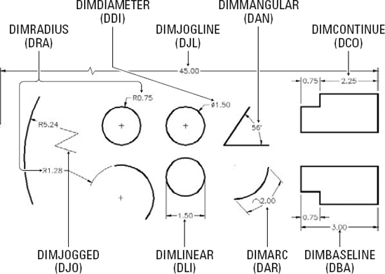
The prompt includes an option to select an object instead of picking two points (you can use this technique with the Linear Dimension command, too):
Specify first extension line origin or <select
        object>:
Press Enter to choose the Select Object option.
AutoCAD prompts you:
Select object to dimension:
Select the line or other object that you want to dimension.
AutoCAD automatically finds the endpoints of the line and uses them as the extension line origin points, as shown in Figure 14-8. (The broken extension line is created with the DIMBREAK command, which is described later in the chapter.)
Specify dimension line location or
[Mtext/Text/Angle]:
Click wherever you want to place the dimension line.
AutoCAD draws the dimension.
If you've created your dimensions using an annotative style, you can set them up so that they change to the appropriate plotted (paper) size when you change the drawing's annotation scale. The process is the same for dimensions as it is for text (covered in Chapter 13) or for hatching (covered in Chapter 15). Refer to Chapter 13 for details.
After you have the hang of ordinary linear dimensions, you should be able to master other common dimension types quickly. Draw some lines, arcs, and circles and try the other dimension commands on the Home tab's Annotation panel (or the fuller set on the Annotate tab's Dimensions panel). If you're using the classic interface, look on the Dimension toolbar or the Dimension menu.

Tip
The QDIM (Quick DIMension) command provides a quick way to draw lots of dimensions that, when necessary, can automatically format themselves into continued and baseline dimensions in one fell swoop. (But wouldn't you know it — QDIM is not included in AutoCAD LT.)
Tip
Arc dimensions created with the DIMARC command measure the length along the circumference of the arc, not the radius. Make sure your industry or office standards agree with this type of dimensioning — the standard way of dimensioning arcs is with a radius dimension like the one shown earlier in Figure 14-3.
After you draw dimensions, you can edit the position of the various parts of each dimension and change the contents of the dimension text. AutoCAD groups all the parts of a dimension into a single object.
The easiest way to change the location of dimension parts is to use grip editing, which I describe in Chapter 10. Just click a dimension, click one of its grips, and maneuver away. You'll discover that certain grips control certain directions of movement. Experiment for a few minutes to see how they work.
If you want to change the look of a component of a specific, individual dimension (for example, substitute a different arrowhead or suppress an extension line), use the Properties palette. (See Chapter 11 for more on the Properties palette.) All the dimension settings in the New Dimension Style and Modify Dimension Style dialog boxes (see "Creating and managing dimension styles," earlier in this chapter) are available in the Properties palette when you select one or more dimensions.
In manual drafting, it's considered bad form to cross object lines (that is, real geometry) with dimension lines or extension lines. Dimension Break (DIMBREAK) prompts you to select a dimension and then an object to break it. In Figure 14-8, the right extension line of the 3.50 horizontal dimension is broken by the lower extension line of the 1.50 vertical dimension.
The Dimension Space (DIMSPACE) command applies a specified separation between existing linear or angular dimensions. Spacing dimensions equally — other than by using the DIMBASELINE command as they're created — requires tedious manipulation with Snap and MOVE.
Tip
If you select one or more dimensions and right-click, the menu displays a number of useful options for overriding dimension settings or assigning a different style.
Warning
When you change a setting in the Properties palette, you're overriding the default style setting for that dimension. If you need to make the same change to a bunch of dimensions, it's better to create a new dimension style and assign that style to them. You can use the Properties palette or the right-click menu to change the dimension style that's assigned to one or more dimensions.
You can use the Properties palette to turn on AutoCAD's background mask feature, described in Chapter 13, for the text of individual dimensions: Select the dimensions, display the Text area in the Properties palette, and find the Fill Color item. Click in the list box, scroll down, and select Background to use the drawing background color (which usually gives the best results). To ensure that dimension text lies on top of other objects, use the DRAWORDER or TEXTTOFRONT command — see Chapter 13 for more information.
Warning
The AutoCAD EXPLODE command on the Home tab's Modify panel (or the classic Modify toolbar) will blow a dimension to smithereens — or at least into a bunch of line and multiline text objects. Don't do it! Exploding a dimension makes it much harder to edit cleanly and eliminates AutoCAD's ability to update the dimension text measurement automatically.
In most cases, you shouldn't have to edit dimension text. Assuming that you draw your geometry accurately and pick the dimension points precisely, AutoCAD displays the right measurement. If you change the size of the associated object, AutoCAD updates the dimension and its measurement. However, you may occasionally want to override the dimension text (that is, replace it with a different measurement) or add a prefix or a suffix to the true measurement.
AutoCAD creates dimension text as a multiline text (Mtext) object, so dimension text has the same editing options as ordinary text. Unfortunately, the right-click menu for dimension objects doesn't include a Text Edit option. You can use the Text Override field in the Properties palette or type ED (the keyboard shortcut for the DDEDIT command) to edit dimension text in the In-Place Text Editor.
AutoCAD displays the true dimension length as text in the actual dimension (and keeps the text up to date if you change the size or location of the object). You can override the true length by typing a specific length or other text string. You can preserve the true length but add a prefix or suffix by inserting <> (that is, the left and right angled bracket characters) as a placeholder for the dimension value. For example, if you enter <> Max., and the actual distance is 12.00, AutoCAD displays 12.00 Max. for the dimension text. If you later stretch the object so that the actual distance changes to 14.50, AutoCAD automatically changes the dimension text to read 14.50 Max. Now you can appreciate the importance of drawing and editing geometry precisely!
Warning
Avoid the temptation to override the default dimension text by replacing the angled brackets with a numeric value. Doing so eliminates AutoCAD's ability to keep dimension measurements current, but even worse, you get no visual cue that the default distance has been overridden (unless you edit the dimension text). If you're overriding dimension text a lot, it's probably a sign that the creator of the drawing didn't pay enough attention to using precision techniques when drawing and editing. I'm not going to point any fingers, but you probably know whom to talk to.
When you add dimey selecting objects or picking points on the objects by using object snap modes, AutoCAD normally creates associative dimensions, which are connected to the objects and move with them. This is the case in new drawings that were originally created in any version of AutoCAD starting with 2002.
Warning
If you have to work on drawings created or last edited in versions older than AutoCAD 2002, you must set the DIMASSOC system variable to 2 before AutoCAD 2009 will create associative dimensions. An easy way to make this change for the current drawing is to open the Options dialog box (choose Tools
Note
You aren't likely to need any of these three commands very often, but if you do, look up the command name in the online help system:
DIMREASSOCIATE: If you have dimensions that aren't currently associative (probably because they were created in older versions of AutoCAD) or are associated with the wrong objects, you can use the DIMREASSOCIATE command (Dimension
DIMDISASSOCIATE: You can use the DIMDISASSOCIATE command to sever the connection between a dimension and its associated object.
DIMREGEN: In a few special circumstances, AutoCAD doesn't automatically update geometry-driven associative dimensions. (Maybe Autodesk should call them "usually fully awake but occasionally asleep at the wheel associative dimensions.") In those cases, the DIMREGEN command will fix things.