Moving, copying, and stretching objects
Manipulating whole objects
Changing pieces of objects
Editing object properties
In Chapter 10 you learn that AutoCAD has several different methods of modifying drawing objects. You also learn how to select those objects in the first place, so you can edit them. Now it's time to roll up your sleeves and get dirty — in this chapter I introduce the primary edit commands in AutoCAD.
The following sections cover the most important AutoCAD editing commands, using command-first editing mode.
Note
As explained in Chapter 10, command-first — or verb-noun editing in AutoCAD-ese — is one of three different approaches to modifying objects in AutoCAD. I concentrate on this method, where you start a command and then you pick the objects on which the command will act, because it's the only method that works for all editing commands in AutoCAD.
Table 11-1 presents an overview of AutoCAD's most frequently used editing commands. It shows the tool icons found on the Ribbon, the classic toolbar, and the classic menu, and it gives the official command name with corresponding alias (where one exists) for the typists in the room. Ribbon buttons are on the Home tab's Modify panel in the 2D Drafting & Annotation workspace. In the AutoCAD Classic workspace, look for these commands on the Modify toolbar and Modify menu.
Table 11-1. AutoCAD's Modify Commands
Command | Modify Panel Button | Modify Toolbar Button | Modify Menu | |
|---|---|---|---|---|
 | ERASE (E) | Erase | Erase | Modify, Erase Edit, Clear |
 | COPY (CO or CP) | Copy | Copy | Modify, Copy (not Edit, Copy) |
 | MIRROR (MI) | Mirror | Mirror | Mirror |
 | OFFSET (O) | Offset | Offset | Offset |
 | ARRAY (AR) | Array (on slideout panel) | Array | Array |
 | MOVE (M) | Move | Move | Move |
 | ROTATE (R) | Rotate | Rotate | Rotate |
 | SCALE (SC) | Scale | Scale | Scale |
 | STRETCH (S) | Stretch | Stretch | Stretch |
 | LENGTHEN (LEN) | Lengthen (on slideout panel) | None | Lengthen |
 | TRIM (TR) | Trim | Trim | Trim |
 | EXTEND (EX) | Extend | Extend | Extend |
 | BREAK (BR); two points | Break | Break | Break |
 | BREAK (BR); 1 point | Break at point (on slideout panel) | Break at point | Break at point |
 | JOIN (J) | Join (on slideout panel) | Join | Join |
 | CHAMFER (CH) | Chamfer (on flyout button) | Chamfer | Chamfer |
 | FILLET (F) | Fillet (on flyout button) | Fillet | Fillet |
 | EXPLODE (X) | Explode | Explode | Explode |
Whether you start an AutoCAD editing command by clicking a Ribbon button, choosing a command from the classic menu bar, or typing a command name or alias, in almost all cases AutoCAD prompts you for points, distances, and options in the command window. Read the prompts during every step of the command, especially when you're figuring out how to use a new editing command. Otherwise, you're unlikely to complete the command successfully.
Tip
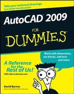
AutoCAD's dynamic input system displays command options at the crosshairs. When you see a dynamic input tooltip with a down arrow icon, press the down-arrow key on the keyboard to display the command options. You then can use the mouse to select an option (see Figure 11-1). Pressing the up-arrow key displays previous input.
As I describe in Chapter 7, maintaining precision when you draw and edit is crucial to good CAD work. If you've used a drawing program and are accustomed to moving, stretching, and otherwise editing objects by eye, you'll need to suppress that habit when you edit in AutoCAD. Nothing ruins a drawing faster than eyeball-editing, in which you shove objects around until they look okay, without worrying about precise distances and points.
Moving, copying, and stretching are, for many drafters, the three most common editing operations. AutoCAD obliges this need with the MOVE, COPY, and STRETCH commands.
The MOVE, COPY, and STRETCH commands all require that you specify how far and in what direction you want the objects moved, copied, or stretched. After you've started the command and selected the objects to be edited, AutoCAD prompts you for two pieces of information:
Specify base point or [Displacement] <Displacement>:
Specify second point or <use first point as displacement>:
In a not-so-clear way, these prompts say that two possible methods exist for you to specify how far and in what direction you want the objects copied, moved, or stretched:
The most common way is to pick or type the coordinates of two points that define a displacement vector. AutoCAD calls these points the base point and the second point (hence, it's called the base point method). Imagine an arrow pointing from the base point to the second point — that arrow defines how far and in what direction the objects get copied, moved, or stretched.
The other way is to type an X,Y pair of numbers that represents a distance rather than a point. This distance is the absolute displacement that you want to copy, move, or stretch the objects (thus it's called the displacement method).
How does AutoCAD know whether your response to the first prompt is a base point or a displacement? It depends on how you respond to the second prompt. (Is that confusing, or what?) First, you pick a point on-screen or enter coordinates at the Base point prompt. Next, there are a couple of possibilities:
If you then pick or type the coordinates of a point at the second point prompt, AutoCAD says to itself, "Aha — displacement vector!" and moves the objects according to the imaginary arrow pointing from the base point to the second point.
If you press Enter at the second prompt (without having typed anything), AutoCAD says, "Aha — displacement distance," and uses the X,Y pair of numbers that you typed at the first prompt as an absolute displacement distance.
Warning
What makes this displacement business even more confusing is that AutoCAD lets you pick a point at the first prompt and press Enter at the second prompt. AutoCAD still says, "Aha — displacement distance," but now it treats the coordinates of the point you picked as an absolute distance. If the point you picked has relatively large coordinates, the objects can get moved way outside the normal drawing area as defined by the limits. The objects fly off into space, and you probably won't see where they've gone because you're zoomed into part of your normal drawing area; it just looks to you like the objects have vanished! In short, be careful when you press Enter during the MOVE, COPY, and STRETCH commands. Press Enter in response to the second prompt only if you want AutoCAD to use your response to the first prompt as an absolute displacement. If you make a mistake, click the Undo button to back up and try again. You can use Zoom Extents (described in Chapter 12) to look for objects that have flown off into space.
The following steps demonstrate command-first editing with the MOVE command, using the base point method of indicating how far and in what direction to move the selected objects. This procedure also gives detailed recommendations on how to use precision techniques when you edit.
Press Esc to make sure that no command is active and no objects are selected.

In the AutoCAD Classic workspace, click Move on the Modify toolbar. The command line displays the
Select objectsprompt.Select one or more objects.
You can use any of the object selection techniques described in the "Perfecting Selecting" section in Chapter 10.
Press Enter when you're finished selecting objects.
AutoCAD displays the following prompt:
Specify base point or [Displacement] <Displacement>:
Specify a base point by clicking a point or typing coordinates.
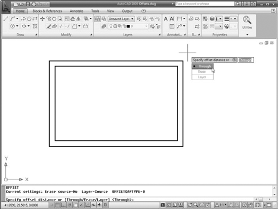
This point serves as the tail end of your imaginary arrow indicating how far and in what direction you want the objects moved. After you pick a base point, it's fairly easy to see what's going on because AutoCAD displays a temporary image of the object that moves around as you move the crosshairs. Figure 11-2 shows what the screen looks like.
Tip
Specify a base point somewhere on or near the object(s) that you're moving. You can use an object snap mode to choose a point exactly on one of the objects.
AutoCAD displays the following prompt:
Specify second point or <use first point as
        displacement>:
Specify the second point by clicking a point or typing coordinates.
The second point serves as the arrow end of your imaginary displacement arrow. After you specify the second point, AutoCAD moves the objects.
Warning
Don't press Enter alone at this prompt! If you do, AutoCAD treats the X,Y coordinates of the first point you picked as an absolute displacement, and the objects fly off unpredictably. I repeat: Don't press Enter alone at this prompt! Pressing Enter without picking a point or typing coordinates at this prompt is one of the most common errors new AutoCAD users make, and it can really pollute your drawing with unwanted objects.
Use an object snap mode to pick a second point exactly on another object in the drawing.
Type a relative or polar coordinate, as described in Chapter 7. For example, if you type @6,2, AutoCAD moves the objects 6 units to the right and 2 units up. If you type @3<45, AutoCAD moves the objects 3 units at an angle of 45 degrees.
Use direct distance entry to move objects in an orthogonal or polar tracking direction. See Chapter 7 for instructions.

The COPY command creates multiple copies by default. If you want only one copy, press Enter after placing it in the drawing. Choosing mOde at the command prompt or the dynamic input menu lets you switch between making a single copy and multiple copies. If you mostly make multiple copies or mostly make single copies, you'll appreciate being able to change the default setting.
Tip
The COPY command includes an Undo option with which you can roll back multiple copies within a single COPY operation.
Warning
If you're using the classic menu, you may have noticed that there's a Copy option on the Edit menu as well as a Copy option on the Modify menu. They're not the same — choosing Edit
You can't copy objects from one drawing to another with the COPY command. Instead, you use the COPYCLIP command together with its companion command, PASTECLIP.
COPYCLIP and PASTECLIP use the Windows Clipboard to temporarily store drawing objects from one file so they can be pasted into another file. The Utilities panel on the Ribbon (and the AutoCAD Classic Standard toolbar) contains Cut, Copy, and Paste tools, the three standard Clipboard buttons you find in every Windows program.
Tip
As you're figuring out where things are hiding in AutoCAD 2009's new Ribbon-based 2D Drafting & Annotation workspace, remember that the standard Windows keyboard shortcuts — Ctrl+X (cut), Ctrl+C (copy), and Ctrl+V (paste) — are still available and are often the most efficient way of using the Windows Clipboard even after you've found the Utilities panel!
Table 11-2 summarizes AutoCAD's most important Clipboard-related commands, along with the equivalent choices on the right-click menu and Ribbon's Utilities panel. (The classic Standard toolbar buttons' tooltips display the same names.)
Table 11-2. AutoCAD Clipboard Commands
Command Name | Right-Click Menu | Utilities Panel Button | Classic Standard Toolbar Button |
|---|---|---|---|
CUTCLIP | Cut | Cut | Cut (Ctrl+X) |
COPYCLIP | Copy | Copy Clip (on Copy flyout) | Copy (Ctrl+C) |
COPYBASE | Copy with Base Point | Copy with Base Point (on Copy flyout) | None (Ctrl+Shift+C) |
COPYLINK | None | Copy Link (on Copy flyout) | None |
PASTECLIP | Paste | Paste | Paste (Ctrl+V) |
PASTEBLOCK | Paste as Block | Paste as Block (on Paste flyout) | None (Ctrl+Shift+V) |
PASTEASHYPERLINK | None | Paste as Hyperlink (on Paste flyout) | None |
PASTEORIG | Paste to Original Coordinates | Paste to Original Coordinates (on Paste flyout) | None |
PASTESPEC | None | Paste Special (on Paste flyout) | None |
The STRETCH command is superficially similar to COPY and MOVE; it has the same inscrutable base point and displacement prompts, and it shifts objects — or parts of objects — to other locations in the drawing. But it also has important differences that often confound new AutoCAD users to the point that they give up trying to figure out how to use STRETCH. That's a mistake because STRETCH is a valuable command. With it, you can perform editing operations in seconds, whereas other commands would take many minutes to use. Here are the things you need to know to make STRETCH your friend:
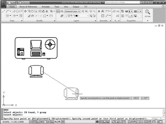
Selecting objects to stretch: To use STRETCH, you must select objects by using a crossing selection box (or crossing polygon), as described in the section on selecting in Chapter 10. See Figure 11-3 for a visual explanation.
Defining points: STRETCH operates on the defining points of objects — endpoints of a line, vertices of a polyline, the center of a circle, and so on — according to the following rule: If a defining point is within the crossing selection box that you specify, AutoCAD moves the defining point and updates the object accordingly.
For example, if your crossing selection box surrounds one endpoint of a line but not the other endpoint, STRETCH moves the first endpoint and redraws the line in the new position dictated by the first endpoint's new location. It's as though you have a rubber band tacked to the wall with two pins, and you move one of the pins.
Compressing and stretching: STRETCH can make lines longer or shorter, depending on your crossing selection box and displacement vector. In other words, the STRETCH command really combines stretching and compressing.
Getting in the mode: It's a good idea to turn on ortho or polar tracking mode before stretching. Otherwise, you'll end up stretching objects in strange directions, as shown in Figure 11-4.

The following steps describe how to stretch lines:
Draw some lines in an arrangement similar to the dark lines shown in Figure 11-5.
Start your stretching with simple objects. You can work up to more complicated objects — polylines, circles, arcs, and so on — after you've limbered up with lines.
Press Esc to make sure that no command is active and no objects are selected.

The command line displays the
Select objectsprompt with a warning to use the Crossing or CPolygon object selection mode:Select objects to stretch by crossing-window or crossing-polygon... Select objects:Pick points to specify a crossing selection box that encloses some, but not all, endpoints of the lines.
Figure 11-5 shows a sample crossing selection box that completely encloses the two vertical lines on the right side of the figure. This crossing selection box cuts through the four horizontal lines, enclosing only one endpoint of each.
Press Enter to end object selection.
AutoCAD displays the following prompt:
Specify base point or [Displacement] <Displacement>:
Specify a base point by object snapping to a point on an existing object or by typing absolute X,Y coordinates.
AutoCAD displays the following prompt:
Specify second point or <use first point as
        displacement>:
Tip
Toggle ortho mode on and then off by clicking the Ortho Mode button on the status bar; try moving the crosshairs around first with ortho on and then with it off to see the difference.
Figure 11-5 shows what the screen looks like as you move the crosshairs around without benefit of ortho or polar tracking.
Toggle ortho mode on (if it isn't already) and then specify the second point — usually by using direct distance entry.
You can also specify the second point by object snapping to a point on an existing object or by typing relative X,Y coordinates.
After you pick the second point, AutoCAD stretches the objects. Notice that the STRETCH command moved the two vertical lines because the crossing selection box contained both endpoints of both lines. STRETCH lengthened or shortened the four horizontal lines because the crossing selection box enclosed only one endpoint of each.

The STRETCH command takes some practice, but it's worth the effort. Draw some additional kinds of objects and practice stretching with different crossing selection box locations as well as different base points and second points.
Tip
The STRETCH command prompt says Select objects to stretch by crossing-window or crossing-polygon but picking points as in Step 4 doesn't give you the crossing-polygon option. (See Chapter 10 if you need a refresher on crossing-polygon selection.) To use a polygonal crossing selection, type CP at the Select objects prompt and press Enter.
The commands in this section — ROTATE, SCALE, ARRAY, and OFFSET — provide other ways (in addition to MOVE, COPY, and STRETCH) of manipulating objects or creating new versions of them. The procedures for each command assume that you're familiar with the object selection and editing precision techniques presented in the MOVE, COPY, and STRETCH procedures (see Chapter 10 and the previous sections in this chapter).
The ROTATE command pivots one or more objects around a point that you specify. Follow these steps to use the ROTATE command:
Press Esc to make sure that no command is active and no objects are selected.

Select one or more objects and then press Enter to end object selection.
AutoCAD prompts you for the base point for rotating the selected objects:
Specify base point:
Specify a base point by clicking a point or typing coordinates.
The base point becomes the point around which AutoCAD rotates the objects. You also have to specify a rotation angle:
Specify rotation angle or [Copy/Reference] <0>:
Specify a rotation angle by typing an angle measurement and pressing Enter, or just press Enter to accept the default value shown in angle brackets.
Alternatively, you can indicate an angle on the screen by moving the crosshairs until the Coordinates section of the status bar indicates the desired angle and then clicking. If you choose this alternative, you will need to use ortho mode or polar tracking to indicate a precise angle (for example, 90 or 45 degrees) or an object snap to rotate an object so that it aligns precisely with other objects.
After you specify the rotation angle by typing or picking, AutoCAD rotates the objects into their new position. The ROTATE command's copy option makes a rotated copy while leaving the source object in place.
If you read all my harping about drawing scales and scale factors in Chapter 4, you may think that the SCALE command performs some magical scale transformation on your entire drawing. No such luck. It merely uniformly scales one or more objects up or down by a factor that you specify. Here's how it works:
Press Esc to make sure that no command is active and no objects are selected.

Select one or more objects and then press Enter to end object selection.
AutoCAD prompts you for the base point about which it will scale all the selected objects:
Specify base point:
Specify a base point by picking a point or typing coordinates.
The base point becomes the point about which the objects are scaled. AutoCAD prompts you for the scale factor:
Specify scale factor or [Copy/Reference] <1.0000>:
Warning
Don't assume that AutoCAD will scale the objects but leave them more or less where they are in the drawing. AutoCAD scales the distance between objects as well as the objects themselves. For example, if you select a circle to scale, pick a point outside the circle as the base point, and then specify a scale factor of 2. AutoCAD not only makes the circle twice as big, but also moves the circle twice as far away from the base point that you specified.
Type a scale factor and press Enter.
AutoCAD then scales the objects by the factor that you type, using the base point that you specified. Numbers greater than 1 increase the objects' sizes. Numbers smaller than 1 decrease the objects' sizes.
Tip
Just like the ROTATE command, SCALE also has a copy option with which you can make enlarged or reduced duplicates of selected objects without altering the source objects. And both SCALE and ROTATE remember the last scale factor or rotation angle entered throughout the drawing session.
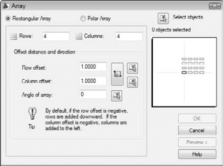
The ARRAY command is like a supercharged COPY: You use it to create a rectangular grid of objects at regular X and Y spacings or a radial arrangement of objects around a center point at a regular angular spacing. For example, you can use rectangular arrays to populate an auditorium with chairs or a polar array to populate a bicycle wheel with spokes.
The following steps describe how to create a rectangular array, which you'll probably do more often than creating a polar array:
Press Esc to make sure that no command is active and no objects are selected.
The Array button is hiding in the Modify panel's slideout; you need to open the slideout to get to the tool button.

The Array dialog box appears, as shown in Figure 11-6. When you start the command, "0 objects selected" appears at the upper right.
Make sure that Rectangular Array is selected and then click the Select Objects button.
The Array dialog box closes temporarily, allowing you to select items to array using any object selection method.
Select one or more objects; then press Enter.
The Array dialog box reappears, and the message below the Select Objects button tells you that objects are selected.
Fill in the five text boxes: Rows, Columns, Row Offset, Column Offset, and Angle of Array.
If you see text boxes labeled Center point and a circular image in the preview, you're doing a polar array. Click the Rectangular Array radio button at the top of the dialog box and carry on.
The Rows and Columns numbers include the row and column of the original objects themselves. In other words, entries of 1 don't create any new objects in that direction. The Row Offset and Column Offset measurements are the distances between adjacent rows and columns. You can use the three buttons to the right of the Row Offset and Column Offset edit boxes to eyeball offset distances, but usually you should specify precise values in the edit boxes. The Angle of Array is the rotation angle of the rectangular array; when the angle is 0 degrees, the array is aligned with the crosshairs.
Click the Preview button.
Once again the Array dialog box disappears, and you see a preview of what the array will look like with your current settings.
Note
In previous versions, the preview display was fixed, so you couldn't really tell what was going on if your array extended beyond the screen. In AutoCAD 2009, you can pan and zoom in the drawing if you need to in order to see the full results.
AutoCAD prompts:
Pick or press Esc to return to dialog or <Right-click
        to accept array>:
Right-click if you're satisfied with the array or press Esc if you want to change the array parameters.
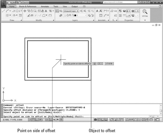
You use OFFSET to create parallel or concentric copies of lines, polylines, circles, arcs, or splines. Follow these steps to use OFFSET:

AutoCAD displays the current command settings and prompts you for the offset distance — the distance from the original object to the copy you're creating:
Current settings: Erase source=No  Layer=Source
        OFFSETGAPTYPE=0
Specify offset distance or [Through/Erase/Layer]
        <Through>:
Type an offset distance and press Enter.
Alternatively, you can indicate an offset distance by picking two points on the screen. If you choose this method, you should normally use object snaps to specify a precise distance from one existing object to another.
AutoCAD prompts you to select the object from which you want to create an offset copy:
Select object to offset or [Exit/Undo] <Exit>:
Select a single object, such as a line, polyline, or arc.
Note that you can select only one object at a time with the OFFSET command. AutoCAD asks where you want the offset object.
Specify point on side to offset or
        [Exit/Multiple/Undo] <Exit>:
Point to one side or the other of the object and then click.
It doesn't matter how far away from the object the crosshairs are when you click. You're simply indicating a direction.
AutoCAD repeats the
Select objectprompt, in case you want to offset other objects by the same distance:Select object to offset or [Exit/Undo] <Exit>:
Go back to Step 3 if you want to offset another object or press Enter if you're finished offsetting objects for now.
Figure 11-7 shows the OFFSET command in progress. For information on the command options — and Multiple, Erase, and Layer are all useful options — look up OFFSET in the online help's Command Reference section.
Tip
If you want to offset a series of connected lines (for example, a rectangular house plan outline or one side of a pathway on a map), make sure that you either draw it as a polyline or convert the individual line and/or arc segments into a polyline with the PEDIT command. (Look up PEDIT in the online help to find out how.) If you draw a series of line segments with the LINE command and then try to offset it, you have to pick each segment and offset it individually. Even worse, the corners usually aren't finished off in the way that you'd expect because AutoCAD doesn't treat the segments as connected. You avoid all these problems by offsetting a polyline, which AutoCAD does treat as a single object. Figure 11-7 shows an offset polyline. See Chapter 8 for more information about the differences between lines and polylines.
The commands in this section — TRIM, EXTEND, BREAK, FILLET, CHAMFER, and JOIN — are useful for shortening and lengthening objects, for breaking them in two, and for putting them back together again.
TRIM and EXTEND are the twin commands for making lines, polylines, and arcs shorter and longer. They're the yin and yang, the Laurel and Hardy, the Jack Sprat and his wife of the AutoCAD editing world. The two commands and their prompts are almost identical, so the following steps cover both. I show the prompts for the TRIM command; the EXTEND prompts are similar:

AutoCAD prompts you to select cutting edges that will do the trimming (or, if you choose the EXTEND command, boundary edges for extending to):
Current settings: Projection=UCS, Edge=None
Select cutting edges ...
Select objects or <select all>:
Press Enter to accept the default option to select all drawing objects, or select individual objects by picking them. Press Enter to end object selection.
The objects you select in this step become the cutting edge of the TRIM command or the boundary to which objects will be extended by the EXTEND command.
Figure 11-8 shows a cutting edge (for TRIM) and a boundary edge (for EXTEND).
AutoCAD prompts you to select objects that you want to trim or extend (EXTEND does not have the eRase option):
Select object to trim or shift-select to extend or
        [Fence/Crossing/Project/Edge/eRase/Undo]:
Select a single object to trim or extend. Choose the portion of the object that you want AutoCAD to trim away or the end of the object that's closer to the extend-to boundary.
AutoCAD trims or extends the object to one of the objects that you selected in Step 2. If AutoCAD can't trim or extend the object — for example, if the trimming object and the object to be trimmed are parallel — the command line displays an error message such as
Object does not intersect an edge.Tip
You can select multiple objects to trim and extend by typing F and pressing Enter to use the Fence object selection mode or by entering C to use Crossing selection. Even better, you can use implied windowing and drag a right-to-left selection box to select multiple objects. Refer to the section on selection boxes Chapter 10 for more on multiple object selection.
The command line continues to prompt you to select other objects to trim or extend:
Select object to trim or shift-select to extend or
        [Fence/Crossing/Project/Edge/eRase/Undo]:
Choose additional objects or press Enter when you're finished trimming or extending.
Tip
Here's a triple-thread tip: If you accidentally trim or extend the wrong object and you're still in the TRIM or EXTEND command, type U and press Enter to undo the most recent trim or extend. You can switch between TRIM and EXTEND without exiting the command by holding down the Shift key for the other tool. And finally, if you find yourself with a remnant that won't trim because it doesn't cross the cutting edge, type R (for eRase) and press Enter to erase it without leaving the TRIM command.
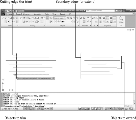
The example in Figure 11-8 shows trimming to a single cutting edge, in which the end of each trimmed line gets lopped off. Another common use of the TRIM command is for trimming out a piece of a line between two cutting edges. In the two-cutting-edges scenario, TRIM cuts a piece out of the middle of the trimmed line. The default option for selecting cutting edges or boundaries is ALL, which works well in this scenario. Pressing Enter to accept the default option selects all objects in the drawing as a cutting edge if you're in the TRIM command, or a boundary if you're in the EXTEND command.

The BREAK command isn't what you use before heading out for coffee. (AutoCAD doesn't have a command for that yet, but I keep hoping.) It's for creating gaps in lines, polylines, circles, arcs, or splines. BREAK also comes in handy if you need to split one object into two without actually removing any visible material.
The following example shows how you BREAK an object (don't worry — in AutoCAD, you won't have to pay for it):

AutoCAD prompts you to select a single object that you want to break.
Select a single object, such as a line, a polyline, or an arc.
Tip
The point you pick when selecting the object serves double duty: It selects the object, of course, but it also becomes the default first break point (that is, it defines one side of the gap that you'll create). Thus, you should either use one of the AutoCAD precision techniques, such as an object snap, to pick the object at a precise point, or use the
First pointoption (described in the next step) to repick the first break point.AutoCAD prompts you to specify the second break point or to type F and press Enter if you want to respecify the first break point:
Specify second break point or [First point]:
If the point that you picked in the preceding step doesn't also correspond to a break point (see the previous tip), type F and press Enter to respecify the first break point. Then pick the point with an object snap or other precision technique.
If you do type F and press Enter and then respecify the first break point, AutoCAD prompts you to select the second break point:
Specify second break point:
Specify the second break point by picking a point or typing coordinates.
AutoCAD cuts a section out of the object, using the first and second break points to define the length of the gap.

Whereas TRIM, EXTEND, and BREAK alter one object at a time, the FILLET and CHAMFER commands modify a pair of objects. As Figure 11-9 shows, FILLET creates a curved corner between two lines, whereas CHAMFER creates a beveled corner. (In case you wondered, it's pronounced FILL-et, not fill-AY. Saying that you know how to fill-AY may get you a job in a butcher shop, but it will get you strange looks in a design office.)

The following steps describe how to use the FILLET command. The CHAMFER command works similarly except that, instead of specifying a fillet radius, you specify either two chamfer distances or a chamfer length and angle.

AutoCAD displays the current fillet settings and prompts you to select the first object for filleting or specify one of three options:
Current settings: Mode = TRIM, Radius = 0.0000
Select first object or [Undo/Polyline/Radius/Trim/
        Multiple]:
Type R and press Enter to set the fillet radius.
AutoCAD prompts you to specify the fillet radius that it uses for future fillet operations:
Specify fillet radius <0.0000>:
Type a fillet radius and press Enter.
The number you type will be the radius of the arc that joins the two lines.
AutoCAD then asks you to select the first object:
Select first object or [Undo/Polyline/Radius/Trim/
        Multiple]:
Select the first line of the pair that you want to fillet.
AutoCAD prompts you to select the second object for filleting:
Select second object or shift-select to apply corner:
Select the second line of the pair that you want to fillet.
AutoCAD fillets the two objects, drawing an arc of the radius that you specified in Step 3.
Tip
You can fillet two lines and specify a radius of zero to make them meet at a point. If you have lots of lines to fillet, whether with a zero or the same nonzero radius, use the FILLET command's Multiple option to speed the process.
Holding down the Shift key before picking the second line automatically gives you a clean intersection, the same as if you'd set the fillet radius to 0. The CHAMFER command has the same Shift-select option.
Use the JOIN command to fill gaps in lines, arcs, elliptical arcs, splines, and polylines. If the lines are collinear (that is, they lie in the same straight line), or the arcs, splines, polylines, or elliptical arcs are on a similarly curved path, JOIN will create a single new entity to replace the existing separate pieces, as shown in Figure 11-10.

The following steps describe how to use the JOIN command:

If you foresee doing a lot of joinery, you can pin the slideout open, as seen in Figure 11-10. AutoCAD prompts you to select the source object.
Select the source object — that is, the object you want to join other objects to.
AutoCAD prompts according to the object type selected. If you select a line, the command prompt or dynamic input tooltip shows
Select lines to join to source:
Select valid objects to join to the original source object.
For example, if you selected a line as your source object, AutoCAD continues prompting for additional collinear lines until you press Enter to end object selection.
Press Enter to end the command.
AutoCAD joins the selected objects into a single object. The new object will inherit relevant properties such as layer or linetype of the source object.
Polishing those properties
When you think of editing objects, you probably think first about editing their geometry: moving, stretching, making new copies, and so on. That's the kind of editing I cover in this chapter.
Another kind of editing is changing objects' properties. As I describe in Chapter 6, every object in an AutoCAD drawing has a set of nongeometrical properties, including layer, color, linetype, lineweight, and maybe plot style. Sometimes, you need to edit those properties — when you accidentally draw something on the wrong layer, for example. A handful of ways of editing an object's properties in AutoCAD are
The Properties palette: This is the most flexible way to edit properties. Select any object (or objects), right-click in the drawing area, and choose Properties from the menu. The Properties palette displays the names and values of all properties. Click in the appropriate value cell to change a particular property.
The Quick Properties panel: New in AutoCAD 2009, if Quick Properties is enabled by clicking its status bar button, a panel pops up near the crosshairs when you select an object. Like the Properties palette, the Quick Properties panel contains value cells that you can click to change the specific property. You can choose which property categories you want Quick Properties to display by right-clicking the Quick Properties status bar button and choosing Settings.
Layers and Properties toolbars: Another way to change properties is to select objects and then choose from the drop-down lists (Layer, Color, and so on) on the Properties panel (or the Layers and the Properties toolbars in the AutoCAD Classic workspace). It's fine to change layers this way, but don't be slap-dash about changing the other properties — see Chapter 6 for more information.
Match Properties: You can use Match Properties to copy the properties from a source object to one or more other objects. You can find the Match Properties button on the Properties panel of the Ribbon's Home tab, or in the Menu Browser or classic menu bar by choosing Modify

Change Space: I introduce the concepts of model space and paper space in Chapters 4 and 5. Sometimes you add some geometry to paper space and then realize it should have been in model space, or vice versa. The former CHSPACE Express tool is now part of core AutoCAD and AutoCAD LT — you'll find it on the Modify menu in the Menu Browser or on the classic Modify menu. For more information, look up CHSPACE in the Command Reference of the online help.
Tip
You can turn an arc into a circle or an elliptical arc into a full ellipse with JOIN's cLose option.