Adding hatching to your drawings
Copying existing hatches
Using predefined and user-defined hatch patterns
Making solid and gradient fills
Using annotative hatching
Choosing hatching boundaries
Editing hatches
If you were hoping to hatch a plot (or plot a hatch), see Chapter 16 instead. If you want to hatch an egg, look for Raising Chickens For Dummies. If you need to fill in closed areas of your drawings with special patterns of lines or solid fills (known as hatching), this is your chapter.
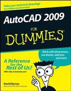
Drafters often use hatching to represent the type of material that makes up an object, such as insulation, metal, concrete, and so on. In other cases, hatching helps emphasize or clarify the extent of a particular element in the drawing — for example, showing the location of walls in a building plan or highlighting a swampy area on a map so you know where to avoid building a road. Figure 15-1 shows an example of hatching in a structural detail.
As I mention in Chapter 13, hatching is another component of AutoCAD's annotative objects. Hatch patterns have a scale factor (as I explain in the "Getting it right: Hatch angle and scale" section, later in this chapter) and can be created so that the hatch scale updates as the annotation scale changes.
An AutoCAD hatch is a separate object that fills a space, has an appearance dictated by the hatch pattern assigned to it, and is associated with the objects that bound the space, such as lines, polylines, or arcs. If you move or stretch the boundaries, AutoCAD normally updates the hatching to fill the resized area.
Warning
Don't go overboard with hatching. The purpose of hatching is to clarify, not overwhelm, the other geometry in the drawing. If your plots look like a patchwork quilt of hatch patterns, it's time to simplify.
Note
Hatching is another kind of annotation of your geometry, similar in purpose to text and dimensions. As I describe at the beginning of Chapter 13, you'll usually be more efficient if you save annotation for later in the drafting process. Draw as much geometry as possible first and then hatch the parts that require it. In other words, batch your hatch.
This section outlines the steps you use to add hatching to a drawing with the Hatch and Gradient dialog box, shown in Figure 15-2. (AutoCAD LT doesn't do gradients, so the dialog box is simply labeled Hatch.) You can use this information to get started quickly with hatching. When you need more information about any part of the process, jump to the relevant sections of "Pushing the Boundary (of) Hatch," later in this chapter.
Tip
By default, the right third of the Hatch and Gradient dialog box is hidden; to see the additional hatch options at the right side of the dialog box as shown in Figure 15-2, click the More Options arrow beside the Help button.
The following steps show you how to hatch an enclosed area by using the "pick points" method of selecting the hatch area:
Open a drawing containing geometry that forms fully closed boundaries, or draw some boundaries by using the drawing commands described in Chapters 8 and 9.
The areas you want to hatch should be completely enclosed. The CIRCLE, POLYGON, and RECTANG commands, and the LINE and PLINE commands with the Close option, make great hatch boundaries (see Chapters 8 and 9 for details).
Set an appropriate layer current, as described in Chapter 6.
Tip
It's usually best to put hatching on its own layer.

The Hatch and Gradient dialog box (or the Hatch dialog box in AutoCAD LT) appears.
Choose Predefined, User Defined, or Custom from the Type drop-down list.
Predefined works best for most purposes. See the "Hatch from scratch" section later in this chapter for details.
If you chose Predefined or Custom in the previous step, select any predefined or custom hatch pattern from the Pattern drop-down list or the Pattern button just to the right of it.
If you chose User Defined, you don't need to choose a pattern.
Specify an Angle and Scale for the hatch pattern. (Or, if you chose User Defined in Step 4, specify Angle and Spacing.)
See the section, "Getting it right: Hatch angle and scale," later in this chapter, for more information.
Select hatch options as required.
For this example, leave the Annotative check box deselected. Try it the old-fashioned way first and then have a look at the "Hatching for the 21st century" section later in the chapter.
Warning
Don't confuse Annotative with Associative, even though both are polysyllabic words that start with A and are right next to one another in the dialog box. Annotative hatch objects rescale themselves when you change the annotation scale in model space or in a viewport. Associative hatch objects (enabled by default) will update to the new area when you change the hatch boundary.
By default, when you select a number of closed areas and then click OK, the hatched areas will be created as a single object; select the Create Separate Hatches check box if you want to be able to modify each hatched area individually. Set the Draw Order drop-down list to specify whether the hatch objects are in front of or behind the hatch boundary or other drawing objects.
Click the Add: Pick Points button.
The Hatch and Gradient dialog box (temporarily) disappears, and your drawing reappears with the following prompt at the command line:
Pick internal point or [Select objects/remove
        Boundaries]:
Pick a point inside the boundary of the area you want to hatch.
AutoCAD analyzes the drawing and decides which boundaries to use. In a complex drawing, this analysis can take several seconds. AutoCAD highlights the boundary that it finds.
Tip
If AutoCAD highlights the wrong boundary, right-click, choose Clear All from the menu, and try again.
Right-click anywhere in the drawing area and choose Enter from the menu to indicate that you're finished selecting points.
The Hatch and Gradient dialog box reappears.
Click the Preview button to preview the hatch.
The Hatch and Gradient dialog box (temporarily) disappears again, and AutoCAD shows you what the hatch will look like:
Pick or press Esc to return to dialog or <Right-click
        to accept hatch>:
Click anywhere in the drawing area to return to the Hatch and Gradient dialog box.
Adjust any settings and preview again until you're satisfied with the hatch.
Click OK.
AutoCAD hatches the area inside the boundary.

Warning
Occasionally, AutoCAD gets confused and doesn't resize a hatch after you resize the boundary. If that happens, erase and then re-create the hatch in the resized area.
The remainder of this chapter shows you how to refine the techniques presented in the preceding section. I describe how to copy existing hatching, take advantage of the various options in the Hatch and Gradient dialog box (including annotative hatches), and choose more complicated hatching boundaries.
You can use predefined, user-defined, or custom hatch patterns. Most of the time, you'll choose either predefined or user-defined hatch patterns, unless some generous soul gives you a custom pattern.
To use AutoCAD's predefined hatch patterns, select Predefined from the Type drop-down list at the top of the Hatch tab in the Hatch and Gradient dialog box. This selection sets the stage for choosing the hatch pattern.
You specify a predefined hatch pattern in one of two ways:
Pattern drop-down list: If you know the name of the hatch pattern, select it from the Pattern drop-down list. The list is alphabetical, except that SOLID (that is, a solid fill) is at the very beginning.
Pattern button: If you don't know the pattern's name or if you prefer the visual approach, click the Pattern button (the tiny button with the ellipsis [three dots] to the right of the Pattern drop-down list and pattern name) to display the Hatch Pattern Palette with pattern previews and names.
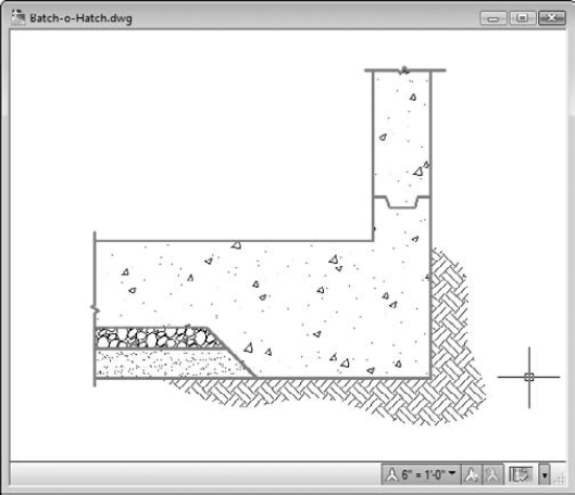
AutoCAD has 72 predefined hatch patterns from which to choose. The list includes ANSI (American National Standards Institute) and ISO (International Organization for Standardization) standard hatch patterns. Figure 15-3 shows the some of the Other Predefined hatch patterns, which cover everything from Earth to Escher to Stars. Hatch patterns whose names begin with AR- are intended for architectural and related industries and use different scaling factors than the non-AR patterns.
After you've selected a pattern, specify angle and scale, as I describe in the section, "Getting it right: Hatch angle and scale," later in this chapter.
A user-defined hatch pattern makes a hatch pattern out of parallel lines. Use this option to create a simple pattern and specify the space between the lines in paper units for annotative hatches or drawing units for non-annotative hatches. For example, you can hatch a wall in a building plan with an annotative user-defined pattern and specify that the hatch lines be 1/8″ apart.
After you choose User Defined from the Type drop-down list in the Hatch and Gradient dialog box, you specify the angle and spacing of the lines. You can select the Double check box to achieve a crosshatching effect (two perpendicular sets of hatching lines). User-defined patterns require that you enter an angle and spacing, not angle and scale.
Predefined and custom hatch patterns require that you enter the angle and scale for AutoCAD to generate the hatching. Usually, you won't have any trouble deciding on an appropriate angle, but a suitable scale can be tricky. Because (with a few exceptions) AutoCAD's hatch patterns don't represent real objects, you don't have to be that precise about scaling them — you can just make them look good. But where do you start?
The answer to that question depends on whether you're using AutoCAD annotative hatching or the old-style, non-annotative hatching. If you're an up-to-the-minute CAD gal or guy, check out the next section, "Hatching for the 21st century." For non-annotative hatching, you need to calculate the hatch scale based on the drawing scale factor, as described in Chapter 4. As a general rule, hatch patterns look best at somewhere between one-half and three-quarters of the drawing scale factor. For example, the EARTH pattern (in the Other Predefined tab of the Hatch Pattern Palette, as shown back in Figure 12-3 and as used in an actual drawing back in Figure 12-1) looks pretty good in a full-scale (1 = 1) drawing with a hatch scale of 0.75. If you're adding EARTH pattern hatching to a 1″ = 1′−0″ detail (drawing scale factor equals 12), try using a hatch scale of 0.75 × 12, or 9.0. Using a consistent multiplier like 0.5 or 0.75 applied to the drawing scale factor ensures that hatching looks consistent (that the spaces between the lines are the same) at all scales when you plot.
Tip
Autodesk created the hatch patterns whose names begin with AR- particularly for use in architectural drawings, and unlike the non-AR patterns, they do represent real objects. The AR-patterns were designed with a final hatch scale of 1.0 in mind, but in some cases, you'll have to adjust up or down in order to achieve a suitable scale.
With annotative hatching, you start with the paper scale (since that's where all your fancy CAD geometry is going to end up) of 1:1. Once again, most patterns look better at between half and three-quarters of the paper scale, so try setting the hatch scale to, say, 0.75. The following steps explain how to create annotative hatching:
Follow Steps 1 to 6 in the "Hatch . . . Hatch . . . Hatchoo" section earlier in the chapter.
Make it solid, man
Although you may not guess it, AutoCAD treats filling an area with a solid color as a type of hatching. Simply choose SOLID from the top of the Pattern drop-down list.
Like any other object, a solid hatch takes on the current object color — or the current layer's color if you leave color set to ByLayer. Therefore, check whether the current object layer and color are set appropriately before you use the Solid hatching option (see Chapter 6 for details).
You can create the effect of a solid fill in AutoCAD in several other ways:
If you want a solid-filled circle, use the DONUT command and specify an inside diameter of
0. (See Chapter 9.)If you want one or more line segments with either uniform or tapered widths, use the PLINE command's Width option. (See Chapter 8.)
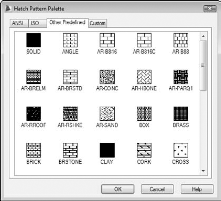
If you want a pattern that starts out solid but then fades away (or transitions to a different color) in one or more directions, use the Gradient tab on the Hatch and Gradient dialog box (not included in AutoCAD LT). This option creates a gradient fill. You can control the color(s), direction(s), and angle of the gradient.
Solid and gradient fills are a good way to mimic poché — an old, hand-drafting technique in which you shade areas with a lighter colored pencil (usually red) to make those areas appear lightly shaded on blueline prints. The figure here shows examples of solid and gradient fills.
In those steps, you open the Hatch and Gradient (just plain Hatch in AutoCAD LT) dialog box and choose a pattern, angle, and scale.
In the Options area of the dialog box, select the Annotative check box.
This time, you're going to create annotative hatch objects.
Continue following Steps 8 to 14 in the "Hatch . . . Hatch . . . Hatchoo" section.
The Hatch and Gradient dialog box appears and disappears as you adjust settings and preview the pattern. When you're in preview mode, AutoCAD prompts:
Pick or press Esc to return to dialog or <Right-click
        to accept hatch>:
When your hatch looks good, right-click to place the hatch and end the command.
AutoCAD hatches the area inside the boundary. If you've correctly created an annotative hatch object, you see the annotative object symbol (the end of a triangular drawing scale) beside the crosshairs if you move your crosshairs over the hatch.
Select the hatch object; then right-click and choose Annotative Object Scale

The Annotation Object Scale dialog box appears and shows a list of all annotative scales assigned to the selected object. In the case of a new hatch object, the only scale listed will be the current annotation scale; if you're doing this in a new drawing that will probably be 1:1, the default value.
In the Annotation Object Scale dialog box, click Add.
The Add Scales to Object dialog box appears, displaying a list of all drawing scale values stored in the drawing.
Select the desired scales from the list, holding down the Ctrl key to select more than one, and then click OK.
The Annotation Object Scale dialog box reappears, with the scales you added displayed in the list box.
Note
Don't go overboard and select every scale in the list — select only the scales you're likely to use.
Click OK.
After you've assigned annotative scales to a hatch (or any annotative) object, you see a pair of triangular annotative object symbols. Don't worry — although you are seeing double, you've done it right!
Open the Annotation Scale drop-down list on the application or drawing status bar and select one of the scales you added to the object.
The annotative hatch objects will change their spacing as you change the annotation scale. If you select a scale from the list that you didn't assign to the object in Step 7, the hatch reverts to the default 1:1 scale.
Figure 15-4 shows two versions of the same drawing, dressed up with annotative and non-annotative hatch patterns. As the annotation scales displayed on the drawing status bars show, the annotative hatches change their scale while the non-annotative hatches remain unchanged. Before annotative hatching first appeared in AutoCAD 2008, the only way to get the effect in these two views was to create two separate layers, one for each hatch scale, and hatch the object twice.
After you specify the hatch pattern, angle, and scale you want to use, you define the boundary (or boundaries) into which you want to pour that hatch pattern in one of two ways:
Picking points within the area(s) you want hatched
Selecting objects that surround those areas

The actual operation involved in using either of these options is confusing to most people. You'll probably need a little practice before you get used to it.
The idea behind either definition option is simple when applied to simple areas — that is, closed areas with no additional objects inside them. To define the hatch boundary for a simple area, do one of these two things:
Click the Add: Pick Points button in the Hatch and Gradient dialog box and then click a point inside the boundary.
Click the Add: Select Objects button and select one or more objects that form a fully closed boundary.
This simple hatching gets more complicated if you have one closed object inside another, as in Figure 15-5. The AutoCAD hatch preview and a bit of experimentation will clarify all these potentially puzzling permutations.
Note
As I warn earlier in this chapter, boundaries should be completely closed before AutoCAD will hatch them. That's one of the reasons you should employ the precision techniques from this book whenever you draw or edit objects. If the lines surrounding your boundary don't either meet exactly or cross, AutoCAD scolds you with a Valid boundary not found error message.
Tip
The Valid boundary not found error message means that you need to repair lines or other objects so they are a fully closed boundary. Sometimes you can use the FILLET command with a zero fillet radius to force two lines to meet exactly. Another possibility is to use grip editing to align one endpoint precisely with another. Chapter 10 discusses these two editing techniques.

With Tool palettes, described in Chapter 2, you can create click-and-drag hatch palettes. With a hatch palette, you click a tool (a swatch) and drag into an enclosed boundary to hatch the area. If your hatching needs are simple, you can create a Tool Palette for the patterns and scales you often use. See "hatches, adding to tool palettes" in AutoCAD's online help for more information.
Editing an existing hatch pattern is simple after you're familiar with the Hatch and Gradient dialog box. Follow these steps:
Alternatively, you can use the Properties palette (described in Chapter 6) to make most existing hatch pattern changes. The Properties palette is especially good for changing several hatches at once. And in AutoCAD 2009, you can use the Quick Properties panel to do the same thing even more efficiently.
Tip
To make one hatch look like another, use the Match Properties button on Properties panel of the Home Ribbon (or the classic Standard toolbar).
The multitude of options in the Hatch and Gradient and Hatch Edit dialog boxes let you tweak your hatch patterns in all sorts of useful and semi-useful ways. You can easily set a new origin point for hatch objects, you can hatch areas that are not fully visible on-screen, and you can optionally hatch multiple boundaries at one go and have the hatches treated as individual objects.
Tip
You can find the area of any hatch object by simply selecting the hatch object and then opening the Properties palette. The area is listed in the Geometry section, near the bottom of the palette.