Drawing precision is vital to good CAD drafting practice, even more than for manual drafting. (Accuracy, of course, is vital to both types of drafting — if you're sketchy on the difference between accuracy and precision, look ahead to the "CAD precision versus accuracy" sidebar later in this chapter.) If you think CAD managers get a little tense when you assign properties directly to objects instead of ByLayer, wait until you see them lay into someone (I sincerely hope it's not you!) who doesn't use precision techniques when creating drawings in AutoCAD.
In AutoCAD, lack of precision makes later editing, hatching, and dimensioning tasks much more difficult and time consuming. Keep these facts in mind:
Small errors in precision in the early stages of creating or editing a drawing often have a big effect on productivity and precision later.
Drawings may guide manufacturing and construction projects; drawing data may drive automatic manufacturing machinery. Huge amounts of money and even lives can ride on a drawing's precision.
In recognition of these facts, a passion for precision permeates the profession. Permanently. Precision is one of the characteristics that separates CAD from ordinary illustration-type drawing work. The sooner you get fussy about precision in AutoCAD, the happier everyone is.
When I talk about drawing things precisely, I mean using precision techniques and tools to specify points and distances with as much exactness as the program allows. Luckily, AutoCAD provides a comprehensive package of tools for doing just that. Table 7-1 lists the more important AutoCAD precision techniques, along with visual cues to the status bar buttons that you click to toggle some of the features.
Note
As I describe in Chapter 2, you can switch the display on status bar buttons between text and icons by right-clicking any of those buttons and selecting or deselecting Use Icons. Table 7-1 shows both versions.
Tip
Precision is especially important when you're drawing or editing geometry — the lines, arcs, and so on that make up whatever you're representing in the CAD drawing. Precision placement usually is less important with notes, leaders, and other annotations that describe, not show.
Table 7-1. Precision Tools and Techniques
Technique | Status Bar Button Label | Status Bar Button Icon | Description |
|---|---|---|---|
Snap mode | SNAP | Forces the crosshairs to move on an imaginary grid of equally spaced "hot spots." | |
— | — | Forces the crosshairs to move specific distances along polar tracking angles. | |
Grid display | GRID | Displays a non-printing reference grid of dots arranged in rows or columns. | |
Ortho mode | ORTHO | Forces the crosshairs to move horizontally or vertically from the previous point. | |
Polar tracking | POLAR | Causes the crosshairs to jump to specified angles. | |
Object snap | OSNAP | Enables picking specific points on existing drawing objects multiple times. | |
Object snap tracking | OTRACK | Causes the crosshairs to locate new points based on multiple object snap points. | |
— | — | Enables picking specific points on existing drawing objects one time only. | |
Coordinate input | — | — | |
Direct distance entry | — | — | Enables you to locate a point by typing a distance and moving the crosshairs to show the direction. |
Note
Before you draw objects, always check the status bar's SNAP, ORTHO, POLAR, OSNAP, and OTRACK buttons and set the buttons according to your precision needs.
A button that looks lit up (that is, just a little brighter than its neighbors) indicates that the feature is on.
A button that looks dimmed indicates that the feature is off.
The most direct way to enter points precisely is to type numbers at the keyboard. AutoCAD uses these keyboard coordinate entry formats:
Note
Cartesian coordinates are named for French philosopher René Descartes (who reasoned, "I think, therefore I am"). In his Discourse on Method, Descartes came up with the idea of locating any point on a planar surface by measuring its distance from a pair of axes (that's axes as in more than one axis, not the tool for chopping wood). In this book, I refer to Cartesian coordinates as X,Y coordinates.
AutoCAD locates absolute X,Y coordinates with respect to the 0,0 point of the drawing — usually its lower-left corner. AutoCAD locates relative X,Y coordinates and relative polar coordinates with respect to the previous point that you picked or typed. Figure 7-1 demonstrates how to use all three coordinate formats to draw a pair of line segments that start at absolute coordinates 2,1; then go 3 units to the right and 2 units up relative to the first point; then relative to that point go 4 units at an angle of 60 degrees.
Note
AutoCAD also understands absolute polar coordinates in the form distance<angle, but this format is almost never useful.
Tip
You can find out the X,Y location of your crosshairs by moving them around in the drawing area and reading the coordinate values at the left end of the status bar. The X,Y coordinates should change as you move the crosshairs. If the coordinates don't change, click the drawing coordinates area until you see <Coords on> in the command window.
Astute observers of the full version of AutoCAD will have noticed that there are three numbers at the left end of the status bar (AutoCAD LT is numerically deprived). AutoCAD is actually showing you the X,Y,Z coordinates of the crosshairs. However, in 2D drafting, the Z value is (or should be) 0, so you can continue calling them X,Y coordinates.

Although it's not apparent at first, there are, in fact, three coordinates display modes. Clicking the coordinates readout cycles through:
Off
<coords off>: The status bar coordinates readout is dimmed, and the coordinate values don't update until you pick a point.On, showing X,Y coordinates
<coords on>: The coordinates readout appears black, and the absolute X,Y coordinates update continuously as you move the crosshairs. If no command is active, clicking the coordinates readout alternates between this mode and<coords off>.On, showing polar coordinates
<coords on>: This mode, which displays distance and angle relative to the last point picked rather than absolute X,Y values, appears if a command is active and AutoCAD is waiting for you to pick a point.
If you start a command such as LINE, pick a point, and then click the Coordinates area a few times, the display changes from coordinates off to live absolute coordinates (X,Y position) to live polar coordinates (distance and angle from the previous point). The live polar coordinates display mode is the most informative a majority of the time.
Warning
When you type coordinates at the command line, do not add any spaces because AutoCAD interprets a space as though you've pressed Enter. This "Spacebar = Enter" weirdness is a productivity feature that's been in AutoCAD forever. It's easier to find the spacebar than the Enter key when you're entering lots of commands and coordinates in a hurry — and it's especially handy for touch typists who are all thumbs.
Note
If you're working in architectural or engineering units, the default unit of entry is inches, not feet. Here are some things to consider about entering numeric values when you work in feet and inches:
To specify feet, you must enter the symbol for feet after the number. For example:
6′ for 6 feet
You can enter a dash to separate feet from inches, as architects often do:
6′−6″ is 6 feet, 6 inches.
Both the dash and the inch mark are optional when you're entering coordinates and distances.
AutoCAD understands 6′6″ and 6′6 as the same as 6′−6″.
If you're typing a coordinate or distance that contains fractional inches, you must enter a dash — not a space — between the whole number of inches and the fraction.
6′6−1/2 (or 6′−6−1/2) represents 6 feet, 6 1/2 inches.
If all this dashing about confuses you, enter partial inches by using decimals instead.
6′6.5 is the same as 6′6−1/2″ to AutoCAD, whether you're working in architectural or engineering units.
After you've drawn a few objects precisely in a new drawing, the most efficient way to draw more objects with equal precision is to grab specific, geometrically precise points, such as endpoints, midpoints, or quadrants, on the existing objects. Every object type in AutoCAD has at least one of these points, and you can "snap" to them precisely as you draw by using object snaps (called osnaps for short by those in the know).
AutoCAD provides two ways of using object snaps:
Here's how you draw precise lines by using object snap overrides:
Open a drawing containing some geometry.

Tip
Although you can use object snap overrides while running object snap mode is turned on, you should turn off running osnap mode while you're getting familiar with object snap overrides. After you've gotten the hang of each feature separately, you can use them together.
Start the LINE command by clicking the Line button on the Ribbon's Draw panel (or AutoCAD Classic's Draw toolbar), or typing LINE (or L ) and pressing Enter.
AutoCAD prompts you to select the starting point of the line:
Specify first point:
Hold down the Shift key, right-click anywhere in the drawing area, and release the Shift key.
The object snap menu appears, as shown in Figure 7-2.
Tip
If you find the Shift+right-click sequence awkward, you can avoid it by using the AutoCAD Classic Object Snap toolbar instead. To turn on the toolbar in the AutoCAD Classic workspace, point to any toolbar button, right-click, and choose Object Snap. In the 2D Drafting & Annotation workspace, right-click anywhere in the Quick Access toolbar and choose Toolbars

Choose an object snap mode, such as Endpoint, from the object snap menu.
The object snap menu disappears, and the command window displays an additional prompt indicating that you've directed AutoCAD to seek out, for example, endpoints of existing objects:
_endp of:
Move the crosshairs slowly around the drawing, pausing over various lines and other objects without clicking yet.
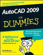
When you move the crosshairs near an object with an endpoint, a colored square icon appears at the endpoint, indicating that AutoCAD can snap to that point. If you stop moving the crosshairs for a moment, a tooltip displaying the object snap mode (for example,
Endpoint) appears to reinforce the idea.Click when the Endpoint object snap square appears on the point you want to snap to.
AutoCAD snaps to the endpoint, which becomes the first point of the new line segment that you're about to draw. The command line prompts you to select the other endpoint of the new line segment:
Specify next point or [Undo]:
When you move the crosshairs around the drawing, AutoCAD no longer seeks out endpoints because object snap overrides last only for a single pick. You can use the object snap right-click menu again to snap the other end of your new line segment to another point on an existing object.
Use the Shift+right-click sequence described in Step 4 to display the object snap menu again. Then choose another object snap mode, such as Midpoint, from the object snap menu.
The command line displays an additional prompt indicating that you've directed AutoCAD to seek, for example, midpoints of existing objects:
_mid of:
When you move the crosshairs near the midpoint of an object, a colored triangle appears at the snap point. Each object snap type (endpoint, midpoint, intersection, and so on) displays a different symbol. If you stop moving the crosshairs, the tooltip text reminds you what the symbol means. Figure 7-3 shows what the screen looks like during this step.
Draw additional line segments by picking additional points. Use the object snap right-click menu to specify a single object snap type before you pick each point.
Try the Intersection, Perpendicular, and Nearest object snaps. If your drawing contains arcs or circles, try Center and Quadrant.
When you're finished experimenting with object snap overrides, right-click anywhere in the drawing area and choose Enter from the menu to end the LINE command.
Note
There's a difference between right-clicking and Shift+right-clicking in the drawing area:
Right-clicking displays menu options for the current command (or common commands and settings when no command is active).
Shift+right-clicking always displays the same object snap menu.

Often, you use an object snap mode (such as Endpoint) repeatedly. Use running object snaps to address this need. (By the way, never run with object snaps in your mouth.)
The following steps set a running object snap:

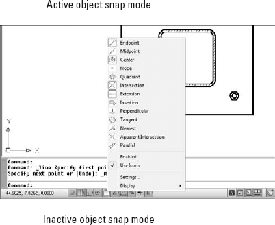
The Object Snap menu appears, as shown in Figure 7-4.
Note
In AutoCAD 2009, the Object Snaps button, together with the Snap Mode, Polar Tracking, and Object Snap Tracking buttons, display a shortcut menu when you right-click, as shown in Figure 7-4. (Object Snaps and Object Snap Tracking both display the menu of running object snaps.) Many settings, including all running object snap modes, can be set by clicking a menu item — you no longer need to open the Drafting Settings dialog box, make your settings, and then click OK to close the dialog box.
Click in the list to select one or more object snap modes.
Active running object snap modes show a highlighted square around the icon (refer to Figure 7-4).
You click the Object Snaps button on the status bar to toggle running object snap mode. After you turn on running object snap, AutoCAD hunts for points that correspond to the object snap modes you checked on the Object Snaps button's shortcut menu. As with object snap overrides, AutoCAD displays a special symbol — such as a square for an endpoint object snap — to indicate that it has found an object snap point. If you keep the crosshairs still, AutoCAD also displays a tooltip that lists the kind of object snap point.
Use object snap overrides or running object snaps to enforce precision by making sure that new points you pick coincide exactly with points on existing objects. In AutoCAD, it's not good enough for points to almost coincide or to look like they coincide. You lose points, both figuratively and literally, if you don't use object snaps or one of the other precision techniques covered in this chapter to enforce precision.
Note
Most, but not all, object snap overrides have running object snap equivalents. For example, Endpoint, Midpoint, and Center work as either overrides or running object snaps, but Mid Between 2 Points works only in override mode.
The following are some other AutoCAD precision techniques (refer to Table 7-1, earlier in this chapter):

Right-click the SNAP button on the status bar.
Choose Settings.
The Snap and Grid tab on the Drafting Settings dialog box appears.
Enter a snap spacing in the Snap X Spacing field and click OK.
Click the Snap Mode button on the status bar (labeled SNAP if your status bar buttons show text) or Press F9 to toggle snap mode off and on. To use snap effectively, change the snap spacing frequently — changing to a smaller spacing as you zoom in and work on smaller areas. You often need to toggle snap off and on because selecting objects and doing some editing tasks are easier with snap off.

Direct distance entry (DDE): This point-and-type technique is an easy and efficient way to draw with precision. You simply point the crosshairs in a particular direction, type a distance at the command line, and press Enter. You can use DDE any time the crosshairs are anchored to a point, and the command line or dynamic input tooltip prompts you for another point or a distance.
You'll usually use DDE with polar tracking turned on to specify distances in particular directions (for example, in angle increments of 45 degrees). You can also combine DDE with ortho mode to specify a distance in an orthogonal direction (0, 90, 180, or 270 degrees).


Note
Remember, you can set a predefined polar tracking angle by right-clicking the Polar Tracking button and choosing it from the menu. If you want to add an angle that's not on the list, you have to click Settings to open the Drafting Settings dialog box.
PolarSnap: You can force polar tracking to jump to specific incremental distances along the tracking angles by changing the snap type from grid snap to polar snap. For example, if you turn on polar tracking and set it to 45 degrees, then turn on polar snap and set it to 2 units, polar tracking jumps to points that are at angle increments of 45 degrees and distance increments of 2 units from the previous point. Polar snap has a similar effect on object snap tracking.
To activate polar snap, right-click the Snap Mode button and choose PolarSnap from the menu. To specify a polar snap distance follow these steps:
Right-click the SNAP button on the status bar.
Choose Settings.
The Snap and Grid tab on the Drafting Settings dialog box appears.
Click the PolarSnap radio button, type a distance in the Polar Distance text box, and then click OK.
When you want to return to ordinary rectangular snap, as described at the beginning of this list, right-click the Snap Mode button and choose Grid Snap from the menu.
Temporary overrides: Settings such as SNAP, ORTHO, and POLAR remain on until you turn them off. You can also use temporary overrides, which last only as long as you hold down their key or key combination. For example, with ortho turned off, holding down the Shift key puts AutoCAD into a temporary ortho mode for as long as you press Shift. For additional information, look up "temporary override keys" in the online help system.
Tip
If you're new to AutoCAD, its wide range of precision tools probably seems overwhelming at this point. Rest assured that there's more than one way to skin a cat precisely (with cats, accuracy is unimportant), and not everyone needs to understand all the ways. You can make perfectly precise drawings without using every single implement in AutoCAD's precision toolkit. I recommend these steps:
Get comfortable with typing coordinates, ortho mode, direct distance entry, and object snap overrides.
Become familiar with running object snaps and try snap mode.
After you have all these precision features under your belt, feel free to experiment with polar tracking, polar snap, and object snap tracking.
Note
It's easy to confuse the names of the snap and object snap (osnap) features. Remember that snap limits the crosshairs to locations whose coordinates are multiples of the current snap spacing. Snap works whether or not there are objects in the drawing. Object snap (osnap) enables you to grab points on existing objects, whether or not those points happen to correspond with the snap spacing.