
Managing layers
Managing other object properties: color, linetype, and lineweight
Copying layers and other named symbols with DesignCenter
CAD programs are different from other drawing programs. You have to pay attention to little details like object properties and the precision of the points that you specify when you draw and edit objects. If you ignore these details and just start drawing, you'll end up with a mess of sloppy geometry that's hard to edit, view, and plot.
This chapter introduces you to object properties, one set of AutoCAD tools and techniques that help you prevent CAD messes. Chapter 7 explains the most important precision drawing techniques that you need to observe in order to create useable AutoCAD drawings. The information in these two chapters is essential to know before you start drawing and editing objects, procedures that I describe in Chapters 8, 9, 10, and 11.
When you first start using AutoCAD, one of its most overwhelming features is the number of property settings and precision controls that you need to pay attention to — even when you draw a simple line. Unlike many other programs, it's not enough to draw a line in a more-or-less adequate location and then slap some color on it. But all those settings and controls can inspire the feeling that you have to find out how to drive a Formula 1 car to make a trip down the street. (The advantage is that, after you are comfortable in the driver's seat, AutoCAD will take you on the long-haul trips and get you there faster.)
Following are the three keys to good CAD drawing practice:
Pay attention to and manage the properties of every object that you draw — especially the layer that each object is on. I explain layers and other object properties in the next section.
Pay attention to and use the named symbols in every drawing — the layers, text styles, block definitions, and other non-graphical objects that serve to define the look of all the graphical objects in the drawing. I enlighten you in the "Using Named Symbols" section later in this chapter.
Pay attention to and control the precision of every point and distance that you use to draw and edit each object. I fill you in on AutoCAD's precision drawing techniques in Chapter 7.
These can seem like daunting tasks at first, but the following sections help you cut them down to size.
All the objects that you draw in AutoCAD are like good Monopoly players: They own properties. In AutoCAD, these properties aren't physical things; they're an object's characteristics, such as layer, color, linetype, lineweight, and plot style. You use properties to communicate information about the characteristics of the objects you draw, such as the kinds of real-world objects they represent, their materials, their relative location in space, or their relative importance. In AutoCAD, you also use properties to organize objects for editing and plotting purposes.
Note
You can view — and change — all of an object's properties in the Properties palette, and many of them in Quick Properties. In Figure 6-1, the Properties palette at the left, and the Quick Properties panel at the right show properties for the selected line object.

Figure 6-1. Comprehensive or quick? Sometimes you need lots of information, and sometimes you don't.
To toggle the full Properties palette on and off, click the Properties button on the View tab of the Ribbon (in the AutoCAD Classic workspace, it's on the Standard toolbar) or use the Ctrl+1 key combination. Before you select an object, the Properties palette displays the current properties — properties that AutoCAD applies to new objects when you draw them. After you select an object, AutoCAD displays the properties for that object. If you select more than one object, AutoCAD displays the properties that they have in common.
Tip
If the Quick Properties button is turned off in the status bar, you can double-click most object types, and the Properties palette will open, displaying information about that object. If Quick Properties is turned on, single- or double-clicking an object opens the Quick Properties panel.
Every object has a layer as one of its properties. You may be familiar with layers — independent drawing spaces that stack on top of each other to create an overall image — from using drawing programs. AutoCAD, like most CAD programs, uses layers as the primary organizing principle for all the objects that you draw. You use layers to organize objects into logical groups of things that belong together; for example, walls, furniture, and text notes usually belong on three separate layers, for a couple of reasons:
Layers give you a way to turn groups of objects on and off — both on the screen and on the plot.
Layers provide the most efficient way of controlling object color, linetype, lineweight, and plot style.
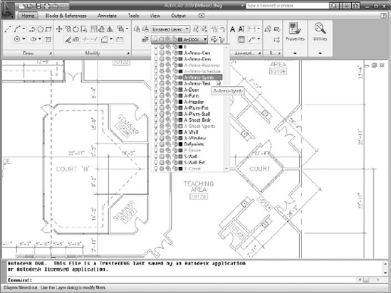
So, to work efficiently in AutoCAD, you create some layers, assigning them names and properties such as color and linetype. Then you draw objects on those layers. When you draw an object, AutoCAD automatically puts it on the current layer — the layer that you see in the Layer Control drop-down list when no objects are selected. If a layer already exists in your drawing, you can make it the current layer by choosing it in Layer Control, as shown in Figure 6-2. In the AutoCAD Classic workspace, the Layer Control drop-down is on the Layers toolbar.
Tip
It's not absolutely necessary to create all your layers before you draw anything, but it will save you some time if you start with a few basic layers and then add new layers as needed. Many experienced AutoCAD users draw things first and then create appropriate layers and change the objects to the new layers. You can easily change an object's layer by selecting it and then choosing the desired new layer name from the Layer Control drop-down list.
Warning
Make sure that no objects are selected before you use the Layer Control drop-down list to change the current layer. (Press the Esc key twice to be sure.) If objects are selected, the Layer drop-down list displays (and lets you change) those objects' layers. When no objects are selected, the Layer drop-down list displays (and lets you change) the current layer.
Besides layers, the remaining object properties that you're likely to want to use often are color, linetype, lineweight, and possibly plot style. Table 6-1 summarizes these four properties.
Table 6-1. Useful Object Properties
Property | Controls |
|---|---|
Color | Displayed color and plotted color or line width |
Linetype | Displayed and plotted dash-dot line pattern |
Lineweight | Displayed and plotted line width |
Plot style | Plotted characteristics (see Chapter 16) |
Warning
Long before AutoCAD was able to display lineweights on the screen and print those same lineweights on paper, object colors controlled the printed lineweight of objects. AutoCAD 2000 introduced a more logical system, where you could assign an actual plotted thickness to objects. As logical as that method seems, the older method, in which the color of objects determines their plotted lineweight, continues to dominate. You may find yourself working this way even in AutoCAD 2009, for compatibility with drawings (and coworkers) that use the old way.
AutoCAD gives you two different ways of controlling object properties:
By Layer: Each layer has a default color, linetype, lineweight, and plot style property. Unless you tell AutoCAD otherwise, objects inherit the properties of the layers on which they're created. When objects are selected in a drawing created using this system, the object properties are listed as ByLayer.
By Object: AutoCAD also enables you to override an object's layer's property setting and give the object a specific color, linetype, lineweight, or plot style that differs from the layer's.
Tip
If you've worked with other graphics programs, you may be used to assigning properties such as color to specific objects. If so, you may be tempted to do the same in AutoCAD. Resist the temptation. Did you catch that? One more time: Resist the temptation.
In almost all cases, it's better to create layers, assign properties to each layer, and let the objects on each layer inherit that layer's properties. Here are some benefits of using the ByLayer approach:
You can easily change the properties of a group of related objects that you put on one layer. You simply change the property for the layer, not for a bunch of separate objects.
Experienced drafters use the ByLayer approach, so if you work with drawings from other people, you'll be much more compatible with them if you do it the same way. You'll also avoid getting yelled at by irate CAD managers, whose job duties include haranguing any hapless newbie who assigns properties to individual objects.
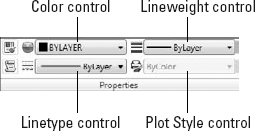
If you take my advice and assign properties ByLayer, all you have to do is set layer properties in the Layer Properties Manager palette (I tell you how in this section), as shown in Figure 6-3. Before you draw any objects, make sure the Color Control, Linetype Control, and Lineweight Control drop-down lists on the Ribbon's Properties panel (or the Properties toolbar in AutoCAD Classic) are set to ByLayer, as shown in Figure 6-4. If the drawing is set to use color-based plot styles instead of named plot styles (see Chapter 16), the Plot Style Control drop-down list will be inactive and will display ByColor.
Note
AutoCAD 2009 replaces the old-style Layer Properties Manager dialog box with a shiny new Layer Properties Manager palette. Like all palettes in AutoCAD, you can leave the Layer Properties Manager open while you do other things in the drawing — unlike the dialog box method of stopping what you're doing, opening the dialog box, making adjustments, closing the dialog box, and then resuming what you were doing. Also like other palettes, the Layer Properties Manager can be set to auto-hide itself to its title bar, to be either float or docked, or to be anchored (do you get the sense that there are some nautical types amongst the AutoCAD programmers?) to either side of the screen.

Tip
If the drawing is set to use named plot styles instead of color-based plot styles (see Chapter 16), the Plot Style control drop-down list should also display ByLayer.
Warning
If you want to avoid doing things the wrong way and getting yelled at by CAD managers, don't assign properties to objects in either of these ways:
Don't make the very common beginner's mistake of choosing a specific color, linetype, lineweight, or plot style from the appropriate drop-down list on the Properties Ribbon panel or toolbar, or from the Properties palette and then drawing the objects.
Don't make the also very common beginner's mistake of drawing the objects, selecting them, and then choosing a property from the same drop-down lists.
If you prefer to do things the right way (that is, my way!), assign these properties ByLayer, as I describe in this section.
Tip
AutoCAD's SETBYLAYER command lets you correct those non-ByLayer properties — from the Menu Browser or the menu bar, choose Modify
If a suitable layer doesn't exist, you need to create one in the Layer Properties Manager palette. Follow these steps:
Click the Layer Properties button on the Ribbon's Layers panel (it's on the Layers toolbar in the AutoCAD Classic workspace) or type LAYER (or LA ) at the command line and press Enter.
The Layer Properties Manager palette appears. A new drawing has only one layer: Layer 0. You need to add the layers necessary for your drawing.
Click the New Layer button (the little yellow explosion just above the Status column) to create a new layer.
A new layer appears. AutoCAD names it Layer1 but highlights the name in an edit box so you can type a new name to replace it easily, as shown in Figure 6-5.
Type a name for the new layer.
Tip
Type the layer name with initial caps (only the first letter of words in uppercase). Layer names written completely in uppercase are much wider, which means that they often get truncated in the Layer Control drop-down list.
On the same line as the new layer, click the color block or color name (White by default) of the new layer.
The Select Color dialog box appears, as shown in Figure 6-6.
The normal AutoCAD color scheme — AutoCAD Color Index (ACI) — provides 255 colors. So many choices are overkill for ordinary drafting.
Tip
For now, stick with the first nine colors — the ones that appear in a single, separate row to the left of the ByLayer and ByBlock buttons on the Index Color tab of the Select Color dialog box — for the following reasons:
These colors are easy to distinguish from one another.
Using a small number of colors makes configuring your plot parameters easier. (I describe the procedure in Chapter 16.)
Note
In the Select Color dialog box, the True Color tab offers a choice of more than 16 million colors, which you can specify by using HSL (Hue Saturation Luminance) or RGB (Red Green Blue) numbers. The Color Books tab enables you to use PANTONE and RAL color schemes, which are popular in publishing. If your work requires tons of colors or close color matching between the computer screen and printed output, you're probably familiar with the relevant color palette and how to use it. If you're using AutoCAD for ordinary drafting or design, stick with the AutoCAD Color Index palette.
Click a color to select it as the color for this layer and click OK.
The Layer Properties Manager palette reappears. In the Color column, the new layer color changes to either the name or the number of the color that you selected.
Note
AutoCAD's first seven colors have both numbers and standard names: 1 = red, 2 = yellow, 3 = green, 4 = cyan, 5 = blue, 6 = magenta, and 7 = white (which appears black when displayed on a white background). The remaining 248 colors have numbers only.
On the same line as the new layer, click the Linetype name of the new layer.
The Select Linetype dialog box appears, as shown in Figure 6-7.
The default AutoCAD linetype is Continuous, which means no gaps in the line.
If you already loaded the linetypes you need for your drawing or if the template file you started from has some linetypes loaded, the Select Linetype dialog box displays them in the Loaded Linetypes list. If not, click the Load button to open the Load or Reload Linetypes dialog box. By default, AutoCAD displays linetypes from the standard AutoCAD or AutoCAD LT linetype definition file —
acad.linfor imperial units drawings oracadiso.linfor metric units drawings (acadlt.linandacadltiso.linin AutoCAD LT). Load the desired linetype by selecting its name and clicking OK.Warning
Unless you have a really good reason (for example, your boss tells you so), avoid loading or using any linetypes labeled ACAD_ISO. These linetypes are normally used only in metric drawings and rarely even then. They overrule everything I'm trying to show you about printed lineweight in what follows, so if at all possible, just say NO to ACAD_ISO. I promise you'll find it easier to use the linetypes with the more descriptive names: CENTER, DASHED, and so on.
Click the desired linetype in the Loaded Linetypes list to select it as the linetype for the layer; say that really fast five times and then click OK.
The Select Linetype dialog box disappears, returning you to the Layer Properties Manager palette. In the Name list, the linetype for the selected layer changes to the linetype you just chose.
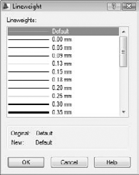
On the same line as the new layer, click the new layer's lineweight.
The Lineweight dialog box appears, as shown in Figure 6-8.
Select the lineweight you want from the scrolling list and click OK.
Tip
The lineweight 0.00 mm tells AutoCAD to use the thinnest possible lineweight on the screen and on the plot. I recommend that, for now, you leave lineweight set to Default and instead map screen color to plotted lineweight, as described in greater detail in Chapter 16.
The Plot style column's contents depend on whether the drawing uses named plot styles or the traditional color-based plotting. Drawings set up to use color-based plotting display an unchangeable plot style name based on the layer's color property. The grayed-out style name changes only when the layer color changes. If, on the other hand, your drawing uses named plot styles, you can assign a named plot style to the layer in this column. (Chapter 16 explains why you might not want to.)
The setting in the Plot column controls whether the layer's objects appear on plots. Click the little printer icon to toggle this setting off (the little printer gets a red bar through it) for any layer whose objects you want to see on the screen but hide on plots.
(Optional) If you want to add a description to the layer, scroll the layer list to the right to see the Description column, click in the Description box corresponding to your new layer, and type a description.
Tip
If you choose to use layer descriptions, stretch the Layer Properties Manager palette to the right so that you can see the descriptions without having to scroll the layer list.
Repeat Steps 2 through 10 to create any other layers that you want.
Select the new layer that you want to make current and click the Set Current button (the green check mark).
Changes you make in the Layer Properties Manager palette are instantaneous, unlike a dialog box in which you have to click OK to close the dialog box and apply the change.
The Layer Control drop-down now displays your new layer as the current layer — the one on which AutoCAD places new objects that you draw.


Note
Well . . . the command name is new anyway. If you're one of those new-trick-hating old dogs who are really attached to doing things in the time-honored fashion, you can enter CLASSICLAYER at the command line to open the . . . er, classic Layer Properties Manager dialog box.
After you create layers, you can set any one of them to be the current layer. Make sure that no objects are selected and then choose the layer name from the Layer Control drop-down list on the Layers panel in the Ribbon or the Layers toolbar.
After you create layers and draw objects on them, you can turn a layer off or on to hide or show the objects on that layer. In the Layer Properties Manager palette, the first three icons to the right of the layer name control AutoCAD's layer visibility modes:
Off/On: Click the light bulb icon to toggle visibility of all objects on the selected layer. AutoCAD does not regenerate the drawing when you turn layers back on. (I give you the lowdown on regenerations in Chapter 12.)
Freeze/Thaw: Click the sun icon to toggle off visibility of all objects on the selected layer. Click the snowflake icon to toggle visibility on. AutoCAD regenerates the drawing when you thaw layers.
Lock/Unlock: Click the padlock icon to lock and unlock layers. When a layer is locked, you can see but not edit objects on that layer.
You can rearrange column order by simply dragging and dropping the column label to a new place. And you can right-click any column label to display a menu from which you can turn columns off and on.
Off/On and Freeze/Thaw do almost the same thing — both settings let you make objects visible or invisible by layer. In the old days, turning layers off and on was often a faster process than thawing frozen layers because thawing layers always required regenerating the drawing. But modern computers, modern operating systems, and recent AutoCAD versions make regenerations much less of an issue on all but the largest drawings. You'll probably find it makes no appreciable difference whether you freeze and thaw layers or turn them off and on.
Tip
You can turn layers off and on, freeze and thaw them, and lock and unlock them by clicking the appropriate icons in the Layer Control drop-down list on the Ribbon (or the Layers toolbar in the AutoCAD Classic workspace).
A load of linetypes
When you load a linetype, AutoCAD copies its linetype definition — a formula for how to create the dashes, dots, and gaps in that particular linetype — from the acad.lin (imperial units) or acadiso.lin (metric units) file into the drawing. (The files are acadlt.lin and acadltiso.lin, respectively, in AutoCAD LT.) The definition doesn't automatically appear in other drawings; you have to load each linetype that you want to use into each drawing in which you want to use it. If you find yourself loading the same linetypes repeatedly into different drawings, consider adding them to your template drawings instead. (See Chapter 4 for information about templates and how to create them.) After you add linetypes to a template drawing, all new drawings that you create from that template will start with those linetypes loaded automatically.
Don't go overboard on loading linetypes. For example, you don't need to load all the linetypes in the acad.lin file on the off chance that you might use them all someday. The resulting linetype list would be long and unwieldy. Most drawings require only a few linetypes, and most industries and companies settle on a half dozen or so linetypes for common use. Your industry, office, or project may have guidelines about which linetypes to use for which purposes.
If you're the techno-dweeb type and don't mind editing a text file that contains linetype definitions, you can define your own linetypes or weed out the ones you'll never use. Choose Contents
Say you have a floor plan of a house that includes a layer showing the framing and another layer showing the wiring. You'd probably never show both of those elements on the same drawing, so you'd need to do some layer management when you showed your drawing to the framers or the electricians. Rather than turning a dozen layers off and a different dozen layers on when you want a different view into your drawing, you can save groups of layer settings as a named layer state. You can manage your layer states in the appropriately named Layer States Manager dialog box by clicking the Layer States Manager button in the Layer Properties Manager. Or you can access the Layer States Manager directly by choosing Format
Note
AutoCAD fades locked layers, giving you a really effective visual reference without confusing you about which layers might be locked or not. You can control the amount of fading by setting a non-zero value for the system variable LAYLOCKFADECTL. (See Chapter 22 for an explanation of system variables, and check out the online help for specific info on this one.) Turn off the fading altogether by setting this value to 0.
Note
If you find yourself using lots of layers, you can create layer filters to make viewing and managing the layer list easier. A group filter is simply a subset of layers that you choose (by dragging layer names into the group filter name or by selecting objects in the drawing). A property filter is a subset of layers that AutoCAD creates and updates automatically based on layer property criteria that you define (for example, all layers whose names contain the word Wall or whose color is green). To find out more, click the Help button on the Layer Properties Manager palette and read about the New Property Filter and New Group Filter buttons.
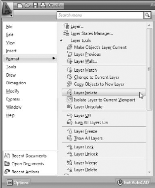
Both AutoCAD and AutoCAD LT include a set of layer tools that, in previous releases, were part of the Express tools that I mention in Chapter 1 (and therefore not available in LT). You can access these Layer tools through the Format menu (see Figure 6-9) on the Menu Browser or the classic menu bar. Layer Isolate and Layer Off are especially useful — you simply click an object to specify the layer to isolate (that is, fade all layers except the chosen one) or turn off altogether. For more information, open the online help system and choose User's Guide
The LAYISO command (Format
Hidden in the innards of every AutoCAD drawing file is a set of named symbols. Named symbols are organized into data tables, and the properties that are common to all AutoCAD objects are defined in these tables. For example, all the line objects in a drawing are stored on one or more layers, so a layer property is common to all lines and is defined in the layer table. But the coordinates that define the start and end points of a given line are unique to that line (or they should be!) — so the coordinate properties are not common to all lines.
Layers are one example of a named symbol. The layer table in a given drawing contains a list of the layers in the current drawing, along with the settings for each layer (color, linetype, on/off setting, and so on).
Named symbols don't appear as graphical objects in your drawing. They're like the hard-working pit crew that keeps the cars running smoothly behind the scenes. The named symbols include
Layers (covered in this chapter)
Linetypes (covered in this chapter)
Text styles (see Chapter 13)
Table styles (see Chapter 13)
Multileader styles (see Chapter 13)
Multiline styles (not covered; see the online help)
Dimension styles (see Chapter 14)
Block definitions and xrefs (see Chapters 17 and 18)
Layouts (see Chapter 5)
When you use commands such as LAYER, LINETYPE, and DIMSTYLE, you're creating and editing named symbols. After you've created named symbols in a drawing, AutoCAD DesignCenter gives you the tools to copy them to other drawings.
DesignCenter is a dumb name for a useful, if somewhat busy, palette. (At least they didn't call it DesignCenter Manager!) The DesignCenter palette is handy for borrowing data from all kinds of drawings. Whereas the Properties palette, described earlier in this chapter, is concerned with properties of graphical objects, the DesignCenter palette deals primarily with named symbols: layers, linetypes, block definitions, text styles, and other organizational objects in your drawings.
The DesignCenter palette (shown in Figure 6-10) consists of a toolbar at the top, a set of four tabs below that, a tree view pane on the left, and a content pane on the right. The tree view pane displays a Windows Explorer-like navigation panel, showing drawing files and the symbol tables contained in each drawing. The content pane usually displays the contents of the selected drawing or symbol table.

The four tabs just below the DesignCenter toolbar control what you see in the tree view and content panes:
Folders: This tab shows the folders on your local and network drives, just like the Windows Explorer Folders pane does. Use this tab if the drawing you want to copy from isn't currently open in AutoCAD.
Open Drawings: This tab (current in Figure 6-10) shows the drawings that are currently open in AutoCAD. Use this tab to copy named objects between open drawings.
History: This tab shows drawings that you've recently browsed in DesignCenter. Use this tab to jump quickly to drawings that you've used recently on the Folders tab.
DC Online: This tab shows parts libraries that are available on Autodesk's and other companies' Web sites. This tab is essentially an advertising vehicle for software companies offering to sell you symbol libraries and manufacturers encouraging you to specify their products. Browse the offerings on this tab to see whether any of the online libraries can be useful in your work.
The toolbar buttons further refine what you see in the tree view and content panes. A few of these buttons toggle different parts of the panes.
The following steps outline the procedure for using DesignCenter to copy named objects from one drawing to another. See the next section, "Copying layers between drawings," for a specific example.
If it isn't already open, use the Menu Browser or the classic menu bar and choose Tools

You can also press Ctrl+2; if you're in the AutoCAD Classic workspace, click DesignCenter on the Standard toolbar.
Select or load the drawing(s) whose content you want to view or use into the navigation pane on the left.
If the source drawing is already open, you can access its content from the Open Drawings tab. If the source drawing is not open but is stored on your hard drive or network, click Load on the DesignCenter toolbar and navigate to the file's location in the Folders tab.
In the Open Drawings tab (if the source drawing is currently open) or the Folders tab (if the source drawing is not open) of the tree view pane, click the + sign beside the source file to expand the list of named symbol categories.
The list of named symbol categories appears in a list in the tree view pane on the left and as icons in the content pane on the right.
In the tree view pane, select the category of named symbol you want to copy.
The content pane now displays the individual named symbols within the named symbol category. For example, in Figure 6-10 (shown previously), the Layers category is selected in the tree view pane, and icons for each named layer are shown in the content pane.
In the content pane, select the items you want to copy. Right-click and choose Add [Symbol] to Drawing or simply drag and drop them into the drawing area.
Use Shift or Ctrl to select multiple named symbols.
The previous set of steps outlines the general procedure for copying named objects from one drawing to another by using DesignCenter. The following steps show a specific example: copying layers from one drawing to another. You can use the same technique to copy dimension styles, layouts, linetypes, table styles, and text styles.
Open the drawing that contains the layers you want to copy (the source drawing).
Open the drawing to which you want to copy the layers (the destination drawing).
If you already had both drawings open, make sure that you can see the destination drawing. If you can't, either open the Window menu and choose the destination drawing in order to bring it to the foreground or tile the windows, as shown in Figure 6-11.
Click the DesignCenter button on the Palettes panel of the Ribbon's View tab or press Ctrl+2.
In the AutoCAD Classic workspace, the DesignCenter button is on the Standard toolbar. The DesignCenter palette appears.
In the DesignCenter palette, click the Open Drawings tab.
The DesignCenter tree view pane on the left side of the palette displays a list of drawings that you currently have open in AutoCAD.
Tip
You can also use the Folders tab, the Load button, or the Search button to load a drawing into DesignCenter without opening it in AutoCAD.
In the tree view pane of the DesignCenter palette, click the plus sign (+) next to the name of the source drawing that you opened in Step 1.
A list of symbol categories that you can copy, including layers, appears in the tree view pane.
Click Layers in the list in the tree view pane.
The display in the content pane at the right changes to show the individual layers that are stored in the source drawing.
Click and drag the desired layer or layers from the content pane of the DesignCenter palette into the window containing the destination drawing that you opened in Step 2, as shown in Figure 6-11.

Warning
If the current drawing contains a layer whose name matches the name of one of the layers you're copying, AutoCAD doesn't change the current drawing's layer definition. For example, if you add a layer named Doors whose color is red into a drawing that already includes a layer called Doors whose color is green, the destination drawing's Doors layer remains green. Named symbols from DesignCenter never overwrite objects with the same name in the destination drawing. AutoCAD always displays the message Duplicate definitions will be ignored even if there aren't any duplicates.
Tip
If you're repeatedly copying named symbols from the same drawings or folders, add them to your DesignCenter favorites list. On the Folders tab, right-click the drawing or folder and choose Add to Favorites from the menu. This procedure adds another shortcut to your list of favorites.
To see your favorites, click the DesignCenter toolbar's Favorites button.
To return to a favorite, double-click its shortcut in the content pane.