It used to be said that "a picture is worth a thousand words." (What with inflation and cost of living increases, a picture is now actually worth 3,780 words!) The opposite is often true as well: Adding a few words to your drawing can save you from having to draw thousands of lines and arcs. It's a lot easier to write Simpson A35 framing clip next to a simple, schematic representation of a clip than to draw one in microscopic detail and hope that the contractor can figure out what it is!
Most CAD drawings include some text in the form of explanatory notes, object labels, and titles. This chapter shows you how to add general drawing text and leaders (descriptive notes with arrows that point to specific drawing objects) to your drawings. I show you how to take advantage of AutoCAD's annotative text objects and text styles, as well as how to find specific text and check your drawing for spelling errors. Chapter 14 covers text that's connected with dimensions.
Tip
In most cases, adding text, dimensions, and other descriptive symbols is something that you should do later in the drafting process, after you've drawn at least some of the geometry. In CAD drawings, text and other annotations are usually intended to complement the geometry, not to stand alone. Thus, you generally need to have the geometry in place before you annotate it. Many drafters find that it's most efficient to first draw as much geometry as possible and then to add text annotations and dimensions to all the geometry at the same time. In this way, you develop a rhythm with the text and dimensioning commands instead of bouncing back and forth between drawing geometry and adding annotations.
As I mention in Chapter 4, AutoCAD's annotative objects present a streamlined way of adding notes, dimensions, and other annotations to your drawings. This chapter introduces annotative text, and subsequent chapters cover annotative dimensions and hatches. See the "Annotatively yours" sidebar, later in this chapter, for some background.
In AutoCAD, adding text to a drawing is only slightly more complicated than adding it to a word processing document. Here are the basic steps, which I explain in more detail in the following sections:
Create a new AutoCAD text style, or select an existing style, that includes the font and other text characteristics you want to use.
Just like a word processor, AutoCAD uses styles — collections of formatting properties — to control the appearance of drawing text. I explain text styles in the next section.
Make an appropriate layer current.
Tip
To make your AutoCAD drawing efficient and easy to edit for both you and others, create text on its own layer. Most drafting offices already have a set of CAD standards that establish specific layers for text and other object types.
Run one of these commands to draw text:
MTEXT draws paragraph (also called multiline) text.
DTEXT draws single-line text.
Specify the text alignment points, justification, and (if necessary) height.
Type the text.
(Optional) For annotative text, assign annotation scales to the text you just typed.
You're probably familiar with most of these steps already — especially if you've ever used a word processor. In the next few sections of this chapter, I review the particularities of AutoCAD text styles, the two kinds of AutoCAD text, and ways of controlling height and justification.
AutoCAD assigns text properties to individual lines or paragraphs of text based on text styles. These text styles are similar to the paragraph styles in a word processor; they contain font and other settings that determine the look and feel of text. An AutoCAD text style includes
The font
A text height, which you can set or leave at
0for later flexibilitySpecial effects (where available), such as italic
Really special effects, such as vertical and upside down, which almost nobody uses
Before you add text to a drawing, use the Text Style dialog box to select an existing style or create a new one with settings that are appropriate to your purpose.
Tip
You can assign the annotative property to text styles in old drawings by opening the Text Style dialog box in the drawing, selecting the individual text style you want to update, selecting the Annotative check box, and then saving the drawing in AutoCAD 2009.
Most drawings require very few text styles. You can create one style for all notes, object labels, and annotations and another text style for special titles. You may also want to create a unique text style for your dimensions (refer to Chapter 14 for more on dimension text). A title block may require one or two additional fonts, especially if you want to mimic the font used in a company logo or project logo.
Tip
As with layers, your office may have its own text style standards. If so, you'll make everyone happy by following those standards. One of the best ways to make your use of text styles efficient and consistent is to create them in a template drawing that you use to start new drawings. (If your office is well organized, it may already have a template drawing with the company-approved styles defined in it.) See Chapter 4 for information about creating and using templates. Another handy technique is to copy existing text styles from one drawing to another by using the DesignCenter palette. See Chapter 6 for instructions.
When you create a text style in AutoCAD, you have a choice of a huge number of fonts. AutoCAD can use two different kinds of fonts: native AutoCAD SHX (compiled shape) fonts and Windows TrueType fonts:
SHX: In the Text Style dialog box, SHX font names appear with a drafting compass to the left of the name and display the
.shxfile extension. SHX fonts usually provide better performance because they're optimized for AutoCAD's use.TrueType: In the Text Style dialog box, TrueType font names appear with a TT symbol to the left of name and no file extension. TrueType fonts give you more and fancier font options, but they can slow down AutoCAD when you zoom, pan, and select and snap to objects. TrueType fonts also can cause greater complications when you exchange drawings with other AutoCAD users.
It's okay to use a TrueType font sparingly for something like a title block logo, but in general, you should stick with standard AutoCAD SHX fonts whenever possible.
Tip
The most popular AutoCAD font is Romans.shx (Roman Simplex). (You may also run into Simplex.shx, an older version of Roman Simplex.) Romans.shx is a good, general-purpose font for drafting in AutoCAD. Avoid complicated, thick fonts. They can slow down AutoCAD, and they're usually more difficult to read than the simpler fonts. Remember, you're doing CAD here, not fancy graphic design or reproductions of medieval manuscripts!
Warning
Whenever possible, avoid custom fonts, which are font files that don't come with AutoCAD or AutoCAD LT (both programs come with the same fonts). AutoCAD installs its standard SHX fonts in the C:Program FilesAutoCAD 2009Fonts folder; as long as you haven't added any custom fonts to that folder, you can refer to it for a list of standard fonts. AutoCAD doesn't embed font files in drawings; instead, it must refer to the font files installed locally under either AutoCAD (for SHX fonts) or Windows (for TrueType fonts). If you use a custom font of either type, exchanging your drawings with other people will be more complicated. If you must use a custom font, make a note of it and remember either to send it whenever you send the DWG file (assuming that the font isn't copyrighted, which many custom fonts are) or to warn the recipients that the text will appear different on their systems. It's far less hassle to avoid custom fonts altogether. See Chapter 19 for additional information about how to deal with fonts when you send and receive drawings.
The following steps describe how to select an existing text style or create a new one before you enter text into a drawing. (If you want to experiment with an existing drawing that contains a variety of text styles, you can use C:Program FilesAutoCAD 2009SampleArchitectural – Annotation Scaling and Multileaders.dwg.) LT users have the same drawing file in LT's sample folder.

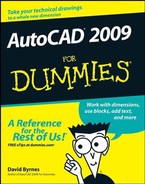
The Text Style dialog box appears, as shown in Figure 13-1.
In the Styles list, select each style in turn to examine the properties of the text styles that have been created in this drawing.
Note the font name and look at the Preview panel in the lower-left corner of the dialog box to get a feel for what the different fonts look like.
If you find a suitable text style, select it in the Styles list, click Set Current, and then skip to Step 9.
What makes a text style suitable depends on industry practices, office standards, and personal preferences about how the text should look. The information in preceding sections may help you decide. If not, ask an experienced drafter in your office or look at some printed drawings and try to match the text on those. If you're starting from scratch, I highly recommend that you use annotative styles — look for the triangular symbol beside the style name.
If you don't find a suitable text style or if you prefer to create your own text style, click New.
Warning
Pay attention to the style that's current when you click New. If it's an annotative style, your new style will automatically be annotative; if it's not annotative, it won't. It's easy enough to select or deselect the Annotative check box, but you may overlook this action at first.
The New Text Style dialog box appears, with a text box for you to type a name.
Type a name for your new text style and then click OK.
Your new text style is added to the Styles list and becomes the current style.
Choose a font from the Font Name list.
Romans.shxis the best all-purpose font for most drafting work. If you'd like to use a different font, review the font suggestions and warnings in the previous section.The font that you choose becomes the font that's assigned to your new text style.
To create an annotative text style, select the Annotative check box. Clear the check box for non-annotative text.
Click the little i icon next to the Annotative label to open AutoCAD's online help and find out more.
Adjust the remaining text style settings.
The text style shown in Figure 13-1 has the following setup:
A text style height of
0.0makes the style variable height, which means that you can specify the height separately for each text object. Assigning a fixed (that is, nonzero) height to a text style forces all text using the style to be the same height. Variable height styles are more flexible, but fixed height styles usually make it easier to draw text of consistent height. The decision to use variable height versus fixed height styles is another aspect of text that depends on office practice, so if you work with other AutoCAD users, ask around.Warning
Dimensions use text styles to format the appearance of the dimension text. When you create a text style that you think you might use for your dimensions, you must set a height of
0. Otherwise, the setting that controls the dimension text will not work, and your dimension text is likely to be either enormous or microscopic. This one should be a double warning because it's one of the most common mistakes made by new AutoCAD drafters!Click Apply and then click Close.
The Text Style dialog box closes, and the text style that you selected or created is now the current style for new text objects.
On the off chance that you're choosing not to use annotative text styles, this section shows you why you might want to change your mind.
In Chapter 4, I describe the importance of choosing an appropriate drawing scale when you set up a drawing. I warn you that you need to know the drawing scale factor for tasks described in other chapters of this book. This is one of those chapters, and I'm about to explain one of those tasks! And when I'm done, remember — you can avoid all the arithmetic by using annotative text — it's just a check box away!
Note
Drawing scale is the traditional way of describing a scale with an equal sign or colon — for example 1/4″ = 1′−0″, 1:20, or 2:1. The drawing scale factor represents the same relationship with a single number, such as 48, 20, or 0.5. The drawing scale factor is the multiplier that converts the first number in the drawing scale into the second number. Make it a point to determine the drawing scale factor of a drawing before you add non-annotative text to it.
Most industries have plotted text height standards (AutoCAD 2009 refers to paper text height, which means the same thing). A plotted text height of 1/8″ or 3 mm is common for notes. Some companies use slightly smaller heights (for example, 3/32″ or 2.5 mm) to squeeze more text into small spaces.
To calculate non-annotative text height, you need to know the drawing scale factor, the desired plotted text height, and the location of the multiplication button on your calculator. Use the following steps to figure out text height:
Determine the drawing scale factor.
If you set up the drawing, you should know its drawing scale, as described in Chapter 4. If someone else set up the drawing, and they're still around, ask them!
Tip
Other methods of figuring out a drawing's scale factor include searching the drawing for a bar scale or text note that indicates the drawing scale, or if a printout is available, measuring dimensioned distances on the hard copy with an architectural or engineering scale. Finally, if the drawing dimensions are in model space, you can check the value of the DIMSCALE variable (the system variable that controls dimension scale), as described in Chapter 14.
Determine the height that your notes should appear when you plot the drawing to scale.
See the preceding "Plotted text height" section for suggestions.
Multiply the numbers that you figured out in Steps 1 and 2.
After you know the AutoCAD text height, you can use it to define the height of a text style or of an individual text object.
If you assign a nonzero height to a text style (Step 8 in the "Get in style" section, earlier in this chapter), all text that you create with that style will use the fixed height. If you leave the text style's height set to 0, AutoCAD asks you for the text height when you draw single-line text objects.
Tip
This discussion of text height assumes that you're adding non-annotative text in model space. In addition to annotative text in model space, there's a third alternative. You can add annotative or non-annotative text to a paper space layout — for example, when you draw text in a title block or add a set of sheet notes that doesn't directly relate to the model space geometry. When you create text in paper space, you specify the actual, plotted paper height instead of the scaled-up height.
For historical reasons (namely, because the AutoCAD text capabilities used to be much more primitive than they are now), AutoCAD offers two different kinds of text objects and two corresponding text-drawing commands. Table 13-1 explains the two commands, with their aliases shown in parentheses.
Table 13-1. The Two Kinds of AutoCAD Text


Although you may be inclined to ignore the older single-line text option, it's worth knowing how to use both kinds of text. The DTEXT command is quite a bit simpler than the MTEXT command, and it's still useful for entering short, single-line pieces of text such as object labels and one-line notes. And it's the command of choice for CAD comedians who want to document their one-liners!
Both the DTEXT and MTEXT commands offer a bewildering array of text justification options — in other words, which way the text flows from the point or points that you pick in the drawing to locate it. For most purposes, the default Left justification for single-line text or Top Left justification for paragraph text works fine. Occasionally, you may want to use a different justification, such as Center for labels or titles. Both commands provide options for changing text justification. I point out these options when I demonstrate the commands later in this chapter.
Despite its limitations, the DTEXT command is useful for labels and other short notes for which MTEXT would be overkill. The following procedure shows you how to add text to your drawing by using AutoCAD's DTEXT command.
Tip
You can use DTEXT for multiple lines of text: Just keep pressing Enter after you type each line of text, and DTEXT puts the new line below the previous one. The problem with this approach is that DTEXT creates each line of text as a separate object. If you later want to add or remove words in the multiple lines, AutoCAD can't do any word-wrapping for you; you have to edit each line separately, cutting words from one line and adding them to the adjacent line.
Note
The DTEXT command doesn't use a dialog box or a fancy formatting toolbar like the MTEXT command's In-Place Text Editor. You set options by typing them into the command line or the dynamic input tooltip.
Here's how you add text with the DTEXT command:
Set an appropriate text style current, as described in the section "Simply stylish text," earlier in this chapter.
It's possible to set an already-created text style current at the DTEXT command prompt, but it's usually more straightforward to set the style before starting the command.
Tip
An alternative to opening the Text Style dialog box to make an existing style current is to click the text style drop-down list and choose the style there. Look for the text style drop-down list on the Annotate panel's slideout or the Text panel of the Annotate tab (in the AutoCAD Classic workspace, it's on the Styles toolbar).
(Optional) Use the OSNAP button on the status bar to enable or disable running object snap mode.
You may or may not want to snap text to existing objects. For example, you'd want to use a Middle object snap to locate a letter or number precisely at the center of a circle.

Don't click the Text button on the Annotation panel (or AutoCAD Classic's Draw toolbar) — that starts the multiline text command, MTEXT, which I cover in the next section.
If this is the first annotative object you're creating in this drawing session, AutoCAD displays a Select Annotation Scale dialog box advising you that you are indeed creating an annotative object and asking you to set the scale at which you want the annotation to appear.
AutoCAD tells you the current text style and height settings and prompts you to select a starting point for the text or to choose an option for changing the text justification or current text style first:
Current text style:  "Standard"  Text height:  0.2000
        Annotative:  Yes
Specify start point of text or [Justify/Style]:
If the text style is annotative, the text height displayed in the prompt is the model space height, not the ultimate plotted text height. For example, if the text style is created with a fixed paper text height of 0.2000, and the annotation scale is set to 1:2, the AutoCAD prompt will read
Text height: 0.4000.If you want to change justification from the default (Left), type J, press Enter, and choose one of the other justification options.
Look up "single-line text, aligning" in the online help system index if you need help with the justification options.
Specify the insertion point for the first text character.
You can enter the point's coordinates from the keyboard, use the mouse to click a point on-screen, or press Enter to locate new text immediately below the most recent single-line text object that you created.
AutoCAD prompts you for the text height (or the paper height if the text style is annotative):
Specify height <0.2000>:
Specify the height for the text.
Note
This prompt doesn't appear if you're using a text style with a fixed (that is, nonzero) height. See the "Simply stylish text" section, earlier in this chapter, for information about fixed versus variable text heights.
AutoCAD prompts you for the text rotation angle:
Specify rotation angle of text <0>:
Specify the text rotation angle by typing the rotation angle and pressing Enter or by rotating the line on-screen with the mouse.
AutoCAD prompts you to type the text.
Type the first line of text and press Enter.
Type additional lines of text, pressing Enter at the end of each line.
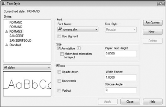
Figure 13-2 shows text appearing on-screen as you type it (or it would if this book had animated pages).
To stop entering text and return to the command prompt, press Enter at the start of a blank line.
AutoCAD adds the new single-line text object — or objects, if you typed more than one line — to the drawing.
Tip
To align lines of text exactly, make sure that you type all the lines in one instance of the DTEXT command, pressing Enter after each line to make the next line appear just after it. Otherwise, aligning different lines of text precisely is harder to do (unless you set your snap just right or use a complicated combination of object snaps and point filters). To edit single-line text after you've created it, select the text, right-click, and choose Edit to open the In-Place Text Editor. ("In-Place" simply means that you edit text at its exact size and location in the drawing.) I tell you more about in-place text editing later in this chapter.
An in-place editing box highlights the selected text object, enabling you to edit the contents of the text string. If you want to edit other text properties, such as text height, select the text, right-click, and choose Properties to display the Properties palette. Use the Properties palette to change parameters as needed.
As I describe in the "Annotatively yours" sidebar, earlier in the chapter, you have a couple of extra steps in the workflow in order to take advantage of single-line or multiline text you create using annotative styles. You have to assign the scales you're likely to use in your drawing to the text objects and then set the annotation scale accordingly. The following steps explain how to assign annotation scales to text that has been created using an annotative text style:
Make sure the text is annotative by hovering the crosshairs over it.
Text created with an annotative style but that has not had any annotation scales applied to it displays a single triangular symbol beside the crosshairs. (The symbol represents the end view of a triangular engineering scale.) If there's no symbol, the text isn't annotative.
Tip
If Quick Properties is enabled at the status bar, you can make individual text objects annotative even if they've been created using a non-annotative style by selecting the text and changing the Annotative property from No to Yes in the Quick Properties panel; you can do the same in the Properties palette by selecting the text and pressing Ctrl+1. There may be times when you would want to do this, but they're probably few and far between. Until you become very familiar with annotative objects and decide how you want to use them in both new and old drawings, I recommend that you stick to creating your annotative text by using annotative text styles rather than assigning the annotative property on individual text objects created with non-annotative styles.
Right-click over a text object and choose Annotative Object Scale

The Annotation Object Scale dialog box appears and shows a list of all annotative scales assigned to the selected object. In the case of a new text or other annotative object, the only scale listed will be whatever annotation scale is set current on the status bar.
In the Annotation Object Scale dialog box, click Add.
The Add Scales to Object dialog box appears, displaying a list of all drawing scale values stored in the drawing.
Select the desired scales from the list, holding down the Ctrl key to select more than one, and then click OK.
The Annotation Object Scale dialog box reappears, with the scales you added displayed in the list box.
Tip
AutoCAD will happily let you select all the scales in the box, but your drawings will be easier to manage if you select only the scales you're likely to use — you can always go back and add another scale later.
Tip
Most of the time, for most people, there are way too many scales listed in the Add Scales to Object dialog box. AutoCAD has a handy dandy Edit Scale List dialog box that lets you remove those imperial scales if you never work in feet and inches. And vice versa, for the metrically challenged. To run through your scales, choose Scale List on the Annotation Scaling panel of the Ribbon's Annotate tab (or Format
Click OK.
After you assign annotative scales to text (or any annotative object), you'll see a pair of triangular annotative object symbols. Don't worry — although you are seeing double, you've done it right!
Open the Annotation Scale list on the application or drawing status bar and select one of the scales you added to the object.
The annotative objects (text in this case) will change their size as you change the annotation scale. If you select a scale from the list that you did not assign to the object in Step 3, the annotative objects disappear unless you turn on the Annotation Visibility toggle on the status bar. There are a lot of options, a mess of settings, and a slew of system variables in this complex feature. To find out more about annotative objects, refer to the New Features Workshop: Select AutoCAD 2008 (the version in which annotative objects were introduced) from the drop-down list and then choose Scale Annotations.
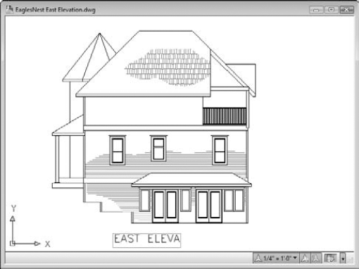
Figure 13-3 shows two versions of the same drawing, with the same text objects (the bulleted notes and windows sizes) displaying at the different annotation scales specified in the two status bars. The non-annotative text (the room label) remains unchanged.
When you just can't shoehorn your creative genius into one or more one-line pieces of text, AutoCAD's multiline text object gives you room to go on and on and on. The following procedure shows you how to create multiline text with the MTEXT command.
Warning
The first part of the MTEXT command prompts you for various points and options. The order is a bit confusing, so read these steps and the prompts carefully.
Here's how you use the MTEXT command:
Set an appropriate text style current and (optionally) turn off running object snap mode, as described in Steps 1 and 2 in the earlier "Using the Same Old Line" section.
If you're doing real drafting, you should also set an appropriate layer current.

The command line displays the current text style and height settings and prompts you to select the first corner of an imaginary rectangle that will determine the word-wrapping width for the text object:
Current text style:  "S-NOTES"  Text height:  0.2000
        Annotative:  Yes
Specify first corner:
Pick a point in the drawing.
The command line prompts you for the opposite corner of the text rectangle that will determine the word-wrapping width and gives you the option of changing settings first:
Specify opposite corner or [Height/Justify/Line
        spacing/Rotation/Style/Width/Columns]:
Type H and press Enter to change the default text height.
The command line prompts you for a new default text height:
Specify height <0.2000>:
Type an appropriate text height.
See the "Taking your text to new heights" section, earlier in this chapter, for information. If you're adding text in model space, I highly recommend that you use annotative text.
The prompt for the opposite corner of the Mtext rectangle reappears. The command line shows
Specify opposite corner or [Height/Justify/Line
        spacing/Rotation/Style/Width/Columns]:
If you want to change justification from the default (top left), type J, press Enter, and choose one of the other justification options.
Look up "multiline text, aligning, Justify Multiline Text" in the index of the online help system if you want an explanation of the other justification options.
Pick another point in the drawing.
Tip
Don't worry about the height of the rectangle that you create by choosing the second point; the width of the rectangle is all that matters. AutoCAD adjusts the height of the text rectangle to accommodate the number of lines of word-wrapped text. Don't worry too much about the width, either; you can adjust it later.
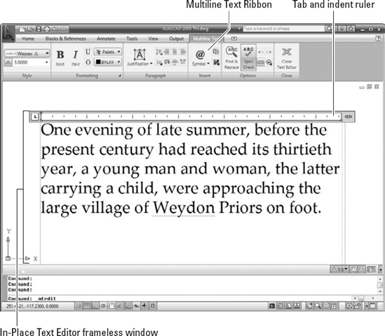
The In-Place Text Editor frameless window appears with the tab and indent ruler above it and — if you're working in the AutoCAD Classic workspace — the Text Formatting toolbar above that.
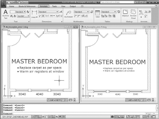
Note
Unless you're toiling away in the AutoCAD Classic workspace, a previously hidden Ribbon tab labeled Multiline Text appears, as shown in Figure 13-4. This new tab is a convenient alternative to the classic Text Formatting toolbar and the In-Place Text Editor's right-click menu.
Note
If you mostly like the 2D Drafting & Annotation workspace but think you'd prefer the classic Text Formatting toolbar instead of the Ribbon's Multiline Text tab, change the value of the new system variable MTEXTTOOLBAR. The default value (2) displays the Multiline Text tab only; setting it to 1 displays both the tab and the toolbar. I don't recommend setting this variable to 0 — that gives you neither option. For more about system variables, see Chapter 22.
Verify the text font and height.
The text font and height should be right if you correctly performed Steps 1, 4, and 5. If not, you can change these settings in the Font drop-down list and the Text Height text box on the Multiline Text tab (or the classic Text Formatting toolbar).
Type text into the text area of the In-Place Text Editor.
AutoCAD word-wraps multiline text automatically. If you want to force a line break at a particular location, press Enter.
Tip
By convention in most industries, text in drawings is always uppercase. How many times have you forgotten to press the Caps Lock key before entering drawing text? How many times have you forgotten to turn Caps Lock off again when it's time to type your e-mail? To save yourself some agony, right-click in the In-Place Text Editor and choose AutoCAPS from the menu.
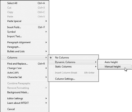
If you want other formatting options, select text, right-click, and make an appropriate choice from the menu (as shown in Figure 13-5).
Click Close Text Editor (or OK in the classic Text Formatting toolbar).
The In-Place Text Editor window closes, and AutoCAD adds your text to the drawing.
Add annotation scales to the new multiline text object.
The steps are the same for multiline text as for single-line text. Refer to the "Turning On Your Annotative Objects" section, earlier in this chapter, if you need a refresher.
As you can tell by looking at the Multiline Text tab and multiline text right-click menu, the MTEXT command gives you plenty of other options. You can show or hide the toolbar, the ruler, or the Options buttons, and you can give the In-Place Text Editor an opaque background. Other panel tool buttons give you access to columns and numbered or bulleted lists (both are covered later in the chapter) and right-clicking presents a shortcut to the New Features Workshop entry on multiline text (choose "Learn about MTEXT").
Between them, the Multiline Text tab and the right-click menu also include a Stack/Unstack feature for fractions, a Find and Replace utility, tools for changing between lowercase and uppercase, options for applying background masks and inserting fields, a special Symbol submenu, and an Import Text option for importing text from a TXT (ASCII text) file or RTF (Rich Text Format) file. I discuss background masks and fields in the next section. If you think you may have a use for any of these other features, choose Contents
Two more useful options on the multiline text right-click menu are Background Mask and Insert Field.
When you turn on background masking, AutoCAD hides the portions of any objects that lie underneath the multiline text. Use these steps to turn on and control this feature:
Right-click in the In-Place Text Editor and choose Background Mask from the menu.
The Background Mask dialog box appears.
Click the Use Background Mask check box so that this option is turned on.
Either click Use Drawing Background Color (to make the mask the same color as the drawing area's background color) or choose a color from the drop-down list (to make the text appear in a solid rectangle of the specified color).
Click OK to return to the In-Place Text Editor.
The Insert Field option on the In-Line Text Editor's right-click menu creates a text field that updates automatically every time you open, save, plot, or regenerate the drawing. Fields can contain data such as the date, filename, or author. Fields draw information from the operating system settings, Drawing Properties dialog box, sheet sets feature (not in AutoCAD LT), and AutoCAD system variables. (For more information about system variables, see Chapter 22.) Use the following procedure to add a field while you're creating multiline text:
On the Annotate tab's Text panel, open the slideout and choose Insert field. In any workspace, right-click in the In-Place Text Editor and choose Insert Field from the menu.
Choose a Field Name in the left column.
Choose a Format in the right column, or for date fields, type a format in the Date Format box.
Click OK.
AutoCAD adds the field to the Mtext object that you're creating or editing.
Tip
If you see four dashes instead of a valid field value, you probably need to do one of the following things:
Regenerate the drawing (see Chapter 12).
Save the drawing.
Fill in Drawing Properties dialog box values (see Chapter 4) and then regenerate the drawing.
Configure sheet sets (see Chapter 16).
Another advantage of Mtext is that it supports bulleted and numbered lists. This feature is especially useful for creating general drawing notes, as shown in Figure 13-6. AutoCAD automates the process of creating numbered lists almost completely. Here's how:
Follow Steps 1 through 8 in the earlier section, "Making it with Mtext," to open the In-Place Text Editor.
Type a title — for example, DESIGN CRITERIA.
If you'd like to have your title underlined, click Underline on the Formatting panel (or the classic Text Formatting toolbar) before you type the title; click Underline again to turn it off. Press Enter to go to the next line and Enter again to leave a little more space.
On the Paragraph panel of the Multiline Text tab, click Numbering; verify that Allow Auto-List, Use Tab Delimiter Only, and Allow Bullets and Lists are selected; and then click Numbered, as shown in Figure 13-6.
The number
1followed by a period appears on the current line, and the cursor jumps to the tab stop visible in the ruler at the top of the In-Place Text Editor window.Note
Enabling Numbered places numerals followed by periods in front of items in a list. (Bulleted places bullet characters in front of items in a list.) Auto-list enables automatic numbering — each time you press Enter to move to a new line, AutoCAD increments the number.
Type the text corresponding to the current number or bullet.
As AutoCAD wraps the text, the second and subsequent lines align with the tab stop, and the text is automatically indented.
Press Enter at the end of the paragraph to move to the next line.
Just like creating numbered lists in your favorite word processor, AutoCAD automatically inserts the next number at the beginning of the new paragraph, with everything perfectly aligned (refer to Figure 13-6).
Tip
To create nested numbered or bulleted items as seen in Figure 13-6, simply press Tab at the start of the line. If you change your mind, you can bump a nested text item up a level by selecting the item in the In-Place Text Editor and pressing Shift+Tab.
Repeat Steps 4 and 5 for each subsequent numbered or bulleted item.
Tip
For legibility, you sometimes want to add spaces between the notes. If you press Enter twice to give yourself a blank line, AutoCAD — like every good word processor — thinks you're finished with your list and turns numbering off. AutoCAD is smart, so you need to be smarter. If you put the cursor at the end of the first note and press Enter, you get a blank line. The problem is, the blank line is now numbered, and your intended Note 2 is now Note 3. Just press the Backspace key. The number on the blank line disappears, and Note 2 is back to being Note 2 again. When you delete a numbered item, the remaining numbers automatically adjust.
If you don't like the horizontal spacing of the numbers or the alignment of subsequent lines, you can adjust them easily by manipulating the tab and indent markers in the In-Place Text Editor's ruler.
In the ruler, drag the upper slider (the triangle pointing down) to the right a short distance. Drag the lower slider (the triangle pointing up) to the right a slightly greater distance.
The upper slider controls the indentation of the first line in each paragraph. The lower slider controls the indentation of the second and subsequent lines. An indent of one to two of the short, vertical tick marks usually works well for the first line. An indent of two to four tick marks works well for the second and subsequent lines.
Click in the ruler just above the lower slider.
A small triangle (pointing right) appears above the lower slider. This triangle shows the tab stop.
Make sure that the corner of the tab stop (right-pointing) triangle aligns horizontally with the point of the lower slider triangle. If not, click and drag the tab stop until it aligns.

Tip
If you prefer to type tab and indent distances, not adjust them with the cursor, open the Paragraph dialog box from the Paragraph panel or the Mtext right-click menu. Whichever way you do it, if you select text first, the tab and indent changes apply to the selected text. If you don't select text first, the changes apply to new text from that point in the multiline text object forward.
AutoCAD is getting more word processor-like with every release! A few versions back, it was simple indents, then came numbered and bulleted lists. The latest addition is columns in multiline text.
Columns come in two flavors: static and dynamic.
With static columns, you specify the number of columns into which to flow your text. Columns are always the same height, and text is allowed to overflow the final column if there's too much of it.
Dynamic columns, as you might expect, are friendlier and more flexible. Column heights can be individually adjusted, and new columns are added automatically to accommodate the text.
Selecting either column type also offers you a Column Settings dialog box where you can specify values numerically instead of by dragging grips.
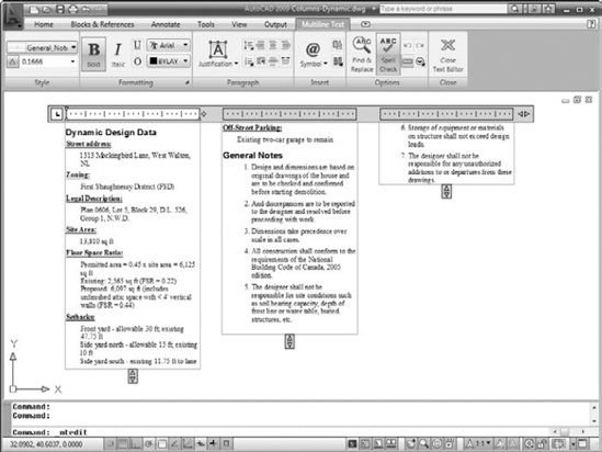
Figure 13-7 shows a block of multiline text imported as an RTF file from a word processor and then formatted in dynamic columns with the Manual Height option.
Setting up columns is pretty straightforward — the following steps explain how:
Open a drawing that contains a large multiline text object, or create a large multitext object in a new drawing.
Tip
If you already have drawing specifications or general notes in a word processor document, or even a text file, you can right-click inside the MTEXT command's In-Place Text Editor and choose Import Text. The Select File dialog box opens, giving you the choice of Rich Text Format (RTF) or ASCII text (TXT) files.
If the In-Place Text Editor is not already open, double-click the text, or right-click it and choose Mtext Edit.
Click Columns in the Insert panel (or the classic Text Formatting toolbar) and choose either Dynamic Columns or Static Columns.
If you choose Dynamic Columns, select either Automatic Height or Manual Height. Selecting Manual Height puts grips on each column so you can adjust their height individually (refer to Figure 13-7). Automatic height displays a single grip, so the heights of all columns remain the same, but new columns are still added as required by the amount of text.
If you choose Static Columns, select the number of columns you want from the menu. Clicking 2, for example, creates two columns regardless of the length of your text — you may end up with overflowing text or empty columns.
Click Close Text Editor (or OK in the Text Formatting toolbar) when you're satisfied with the column arrangement.
You can revert to a non-columnar arrangement by clicking the Columns button in the Insert panel and choosing No Columns.
After you create a multiline text object, you can edit it like in the same ways as a single-line text object: Select the object, right-click, and choose Mtext Edit or Properties.
The Mtext Edit option opens the In-Place Text Editor window so that you can change the text contents and formatting.
The Properties option opens the Properties palette, where you can change overall properties for the text object.
The easiest way to change the word-wrapping width of a paragraph text object is to grip edit it. Select the text object, click one of the corner grips, release the mouse button, move the crosshairs, and click again. Chapter 10 describes grip editing in detail.

You don't know the meaning of the word tedious unless you've tried to create a column-and-row data table in older versions of AutoCAD using the LINE and DTEXT commands. AutoCAD's table object and the TABLESTYLE and TABLE commands for creating it make the job almost fun.
Note
Table objects in AutoCAD 2009 are not annotative, so you have just two methods of adding them to drawings. You can create them in model space, scaling them up by the drawing scale factor (see Chapter 4 for a refresher), or — and this seems more sensible to me — you can create them in a layout, in paper space, defining them by their actual plotted (paper) dimensions.
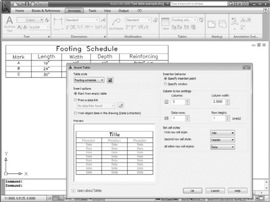
You control the appearance of tables — both the text and the gridlines — with table styles (just as you control the appearance of standalone text with text styles). Use the TABLESTYLE command to create and modify table styles. Follow these steps to create a table:

In the Styles list, select the existing table style whose settings you want to use as the starting point for the settings of your new style.
For example, select the default table style named Standard.
Click the New button to create a new table style that's a copy of the existing style.
The Create New Table Style dialog box appears.
Enter a New Style Name and click Continue.
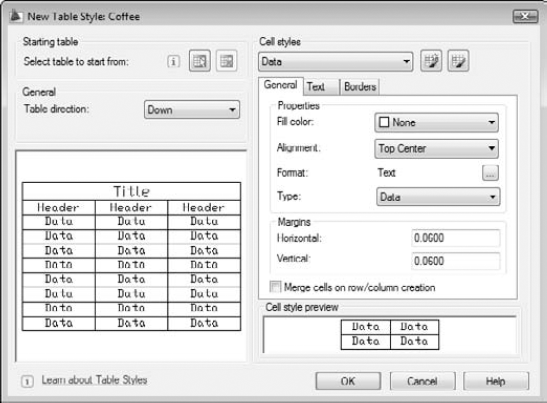
The New Table Style dialog box appears, as shown in Figure 13-8.
In the Cell Styles area, with "Data" showing in the list box, specify settings for the data alignment, margins, text, and borders.
The settings you are likely to want to change are Text Style, Text Height, and perhaps either Text Color (all three are on the Text tab) or Grid Color (on the Borders tab). If you leave colors set to ByBlock, then the text and grid lines will inherit the color that's current when you create the table. That color will be the current layer's color, if you follow my advice in Chapter 6.
In the Cell Styles area, open the drop-down list and repeat Step 5 for the Headers (that is, the column headings) and the Title.
Click OK to close the New Table Style dialog box.
The Table Style dialog box reappears.
(Optional) Select your new table style from the Styles list and then click Set Current.
Your new table style becomes the current table style that AutoCAD uses for future tables in this drawing.
Click Close.
The Table Style dialog box closes. Now you're ready to create a table, as described in the next section.
Tip
You can access the Table Cell Format dialog box directly from the Title, Column Head, or Data pages of the New Table Style dialog box. The Table Cell Format dialog box provides a number of additional options for formatting cells by data type.
AutoCAD stores table styles in the DWG file, so a style that you create in one drawing isn't immediately available in others. You can copy a table style from one drawing to another with DesignCenter. (Use the procedure for borrowing dimension styles outlined in Chapter 6, but substitute Table Styles for Layers.)
After you create a suitable table style, adding a table to your drawing is easy with the TABLE command. Here's how:
Set an appropriate layer current.
Assuming that you leave the current color, linetype, and lineweight set to ByLayer, as I recommend in Chapter 6, the current layer's properties will control the properties of any parts of the table that you left set to ByBlock when you defined the table style. (See Step 5 in the preceding section, "Tables have style, too.")

Choose a table style from the Table Style Name drop-down list.
Choose an Insertion Behavior:
Specify Insertion Point is the easiest method and means that you pick the location of the table's upper-left corner (or lower-left corner if you set Table Direction to Up in the table style). With this method, you specify the default column width and number of rows in the Insert Table dialog box.
Specify Window means that you pick the upper-left corner and then the lower-right corner. With this method, AutoCAD automatically scales the column widths and determines how many rows to include.
Specify Column & Row Settings.
If you chose Specify Window in Step 4, AutoCAD sets the Column Width and number of Data Rows to Auto, which means that AutoCAD will figure them out based on the overall size of the table that you specify in Steps 7 and 8.
Click OK.
AutoCAD prompts you to specify the insertion point of the table.
Click a point or type coordinates.
If you chose Specify Insertion Point in Step 4, AutoCAD draws the table grid lines, places the cursor in the title cell, and displays the Multiline Text tab on the Ribbon (or the Text Formatting toolbar in the AutoCAD Classic workspace).
If you chose Specify Window in Step 4, specify the diagonally opposite corner of the table.
AutoCAD draws the table. Based on the table size that you indicated, AutoCAD chooses the column width and number of rows.
Type a title for the table.
Type values in each cell, using the arrow keys or Tab key to move among cells.
The cell right-click menu offers many other options, including copying contents from one cell to another, merging cells, inserting rows and columns, changing formatting, and inserting a block (that is, a graphical symbol — see Chapter 17 for information about blocks).
Tip
The fields feature described earlier in this chapter works for table text, too — you can insert a field into a table cell. For example, you might use this feature to create part of a title block, with fields serving as the "date" and "drawn by" data.
Click Close Text Editor on the Ribbon or click OK on the Text Formatting toolbar.
Figure 13-9 shows a completed table, along with the Insert Table dialog box.
You can edit cell values later simply by double-clicking in a cell. To change column width or row height, click on the table grid and then click and move the blue grips. (To change the width of one column without altering the overall width of the table, hold down the Ctrl key while you move the grip.) If you want to change other aspects of a table or individual cells in it, select the table or cell and use the Quick Properties panel or the Properties palette to make changes.
Note
You can import tables from Microsoft Excel instead of using the Insert Table dialog box. To import Excel data, in Excel, select the desired cells and choose Edit
You can go the other direction — from AutoCAD to Excel or another program — via a CSV (Comma Separated Value) file. Look up "TABLEEXPORT command" in AutoCAD's online help index.
Tip
You can extract attribute data to tables. See Chapter 17 for information about blocks and attributes. You can also perform simple calculations in tables by using predefined functions or your own arithmetical expressions. Look up "Use Formulas in Table Cells" in AutoCAD's online help Search page.
Don't worry; I'm not going to give you a sales pitch about office politics or personal growth opportunities! No, I'm talking about those notes with arrows that point to drawing objects that you need to embellish with some verbiage.
Multileaders — mleaders for short — are a vast improvement over old-style leaders available prior to AutoCAD 2008. In fact, they're so good, they should be running the United Nations! Mleaders, unlike the old-style leaders, are single objects. They are also able to point in multiple directions at once (just don't ask them which way is the bus station). Finally, multileaders — just like text, dimensions, hatching, and other objects you use to document your drawing — can be annotative.
Warning
There are two older style leaders stored in AutoCAD's attic (Autodesk hates to throw anything away). These semi-retired leaders are no longer accessible on menus or toolbars, but they're still lurking up there waiting to . . . er, lead you astray. If you've become attached to typing commands, you may be inclined to type either LEADER or LE to create those pointy-headed thingies. If you do, be aware that LEADER runs the positively ancient command for creating notes-with-arrows. There are no options, so only straight leader lines and infinitely long text strings are what you get. LE (the alias for the QLEADER command) runs the merely elderly command for creating notes-with-arrows; this one has a Settings dialog box where you can set some options, and it does ask you to specify a width for your Mtext note. However, unlike multileaders, both LEADER and LE create the leader lines and the text as two separate objects.
You can draw multileader objects that consist of leader lines and multiline text at the same time by using the MLEADER command, as described in the following steps:
Set a multileader style — one that's appropriate for your needs — current.


The command line prompts you to select the location for the pointy end of the leader arrowhead:
Specify leader arrowhead location or [leader Landing
first/Content first/Options] <Options>:
The initial default method is to locate the arrowhead followed by the leader landing (that is, the short horizontal line between the leader line and the text), at which point AutoCAD displays the In-Place Text Editor, and you enter the text of your note. If you'd rather place the leader landing first, type L and press Enter. If you'd rather type the content first, type C and press Enter.
If you want to draw spline-curved rather than straight leader lines, specify the number of pick points for the leader lines and press Enter to display multileader options at the command line or the dynamic input tooltip. Refer to the online help for more information on the command options.
Pick a location in the drawing that you want the leader to point to.
If you use an object snap mode, such as Nearest or Midpoint, to pick a point on an object, AutoCAD associates the leader with the object. If you later move the object, AutoCAD updates the leader so that it points to the new location.
The command line prompts you for the next point.
Pick a second point.
AutoCAD draws a shaft from the arrowhead to this point.
Warning
If you pick a second point that's too close to the arrowhead point, and AutoCAD doesn't have enough room to draw the arrowhead, it omits the arrowhead.
By default, AutoCAD lets you pick two points for the leader line: the first point locates the arrowhead, and the second point locates the start of the short horizontal leader landing. If you need more points than that, restart the command and choose Options, Maxpoints and set a new value.
After you pick the point for the leader landing, AutoCAD opens the In-Place Text Editor.
Enter your comment.
You're now in the same In-Place Text Editor I describe earlier in this chapter, with the same Text Formatting toolbar and all the options described in that chapter.
Click OK.
The In-Place Text Editor window closes and adds your comment to the drawing, next to the leader.
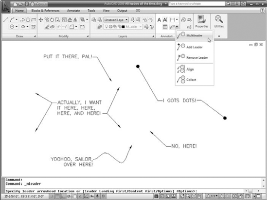
Figure 13-10 shows several different leaders with notes.
In addition to the MLEADER command itself, which I walk you through in the preceding steps, multileaders come with a slew of formatting, drawing, and editing commands:
MLEADEREDIT: Use this command to add or remove leader lines from multileader objects. You'll find each of those functions on the Multileader drop-down menu (refer to Figure 13-10). In the AutoCAD Classic work-space, choose Modify
MLEADERSTYLE: Multileaders, like text, tables, and dimensions, are formatted according to named styles. To display the Multileader Style Manager dialog box (which looks a lot like a simplified version of the Dimension Style Manager) click Multileader Style on the Home tab's Annotation slideout, (or choose Format
MLEADERALIGN: A tedious chore in earlier AutoCAD versions was getting all the leaders to line up; it usually involved drawing a construction line and then using object snaps to move common points on the leaders to the construction line. To line up mleaders, choose Align from the Multileader drop-down menu (or choose Align Multileaders from the classic Multileaders toolbar).
MLEADERCOLLECT: Multileaders can contain blocks as well as text (I cover blocks in Chapter 17). Choose Collect from the Multileader drop-down menu to gather a group of leaders containing blocks; they'll rearrange themselves as a single multileader containing the multiple blocks.
For more information on any of these commands, look them up by name in the Command Reference section of the online help.
Note
Multileaders and multileader styles can be annotative or non-annotative. Making them annotative and assigning appropriate annotation scales is a huge time saver for detail views that you might want to plot at different scales.