Setting up a simple drawing
Drawing some objects
Zooming and panning in your drawing
Editing some objects
Plotting your drawing
The previous two chapters introduce you to the AutoCAD world and the AutoCAD interface. The chapters that follow present the techniques that underlie good drafting practice. By now, you're probably eager to start moving the crosshairs around and draw something! This chapter takes you on a gentle tour of the most common CAD drafting functions:
Setting up a new drawing
Drawing some objects
Editing those objects
Zooming and panning so that you can view those objects better
Plotting (printing) the drawing
Much of the stuff in this chapter may be mysterious to you. Don't worry — I tell you where to look for more information on specific topics. In this chapter, you're simply taking AutoCAD out for a test drive to get a feel for what it can do. Go ahead and kick the tires — and don't worry about putting a dent in the fender!
In this chapter, you create a drawing of an architectural detail — a base plate and column, shown in Figure 3-1. Even if you don't work in architecture or building construction, this exercise gives you some simple shapes to work with and demonstrates commands you can use in most drafting disciplines. And who knows — if the CAD thing doesn't work out, at the very least you'll know how to put your best footing forward.
The figures in this chapter and throughout the book show AutoCAD running in the new Ribbon-based 2D Drafting & Annotation workspace that's present in both the full version of AutoCAD and AutoCAD LT. In the exercise steps in this chapter I emphasize ribbon input, but also point out alternative ways of executing commands using the traditional AutoCAD Classic workspace. I suggest that you try the different input methods described in this chapter. Then, as I explain in Chapter 2, you should feel free to choose whichever interface seems more useful to you.
Although the drafting example in this chapter is simple, the procedures that it demonstrates are real, honest-to-CADness, proper drafting practice. I emphasize from the beginning the importance of proper drawing setup, putting objects on appropriate layers, and drawing and editing with due concern for precision. Some of the steps in this chapter may seem a bit complicated at first, but they reflect the way that experienced AutoCAD users work. My goal is to help you develop good CAD habits and do things the right way from the very start.
Tip
The step-by-step procedures in this chapter, unlike those in most chapters of this book, form a sequence. You must do the steps in order. It's like learning to drive, except that here you're free to stop in the middle of the street and take a break.

Note
If you find that object selection or editing functions work differently from how I describe them in this chapter, you or someone else probably changed the configuration settings on the Option dialog box's Selection tab. Chapter 10 describes these settings and how to restore the AutoCAD defaults.
In this chapter, I walk you through creating, editing, viewing, and plotting a new drawing — refer to Figure 3-1 if you want to get an idea of what the finished product looks like. You can follow these steps using either imperial or metric units; I show metric values in brackets after the imperial ones, like this: Type 1.5 [38] and press Enter.
Note
Pay attention to AutoCAD's feedback. Glance at the messages AutoCAD sends after each step via the dynamic input tooltip, and especially the command window, so that you begin to get familiar with the names of commands and their options. (If you don't see any messages next to the crosshairs, click the DYN button on the status bar.)
In this first set of steps, you create a new drawing from a template, change some settings to establish a 1:10 (that is, 1 inch or 1 millimeter on the drawing is equivalent to 10 inches or 10 millimeters on the real object) scale, and save the drawing. As I describe in Chapter 4, drawing setup is not a simple task in AutoCAD. Nonetheless, drawing setup is an important part of the job, and if you don't get in the habit of doing it right, you run into endless problems later on — especially when you try to plot. (See Chapter 16 for the lowdown on plotting your drawings.)
Start AutoCAD by double-clicking its shortcut on the Windows desktop.
If you don't have an AutoCAD shortcut on your desktop, choose Start

The three workspaces in AutoCAD 2009 look very similar to one another. To make sure you're in the same workspace that I am, click the big red A to open the Menu Browser and then choose Tools
Open the Menu Browser and choose File
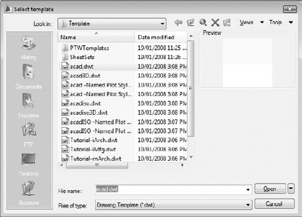
Don't click the New button — use the menu. I explain why in Chapter 4, but just humor me for now. The Select Template dialog box appears with a list of drawing templates (DWT files), which you can use as the starting point for new drawings. Chapter 4 describes how to create and use drawing templates.
Select the
acad.dwt(acadiso.dwt) template, as shown in Figure 3-2, and click Open. (For AutoCAD LT, selectacadlt.dwt[acadltiso.dwt].)AutoCAD creates a new, blank drawing with the settings in
acad.dwtoracadiso.dwt. acad.dwt (acadlt.dwtin AutoCAD LT) is AutoCAD's default, plain-Jane drawing template for drawings in imperial units (that is, units expressed in inches and/or feet).acadiso.dwt (acadltiso.dwtin AutoCAD LT) is the corresponding drawing template for drawings created in metric units. Chapter 4 contains additional information about these and other templates.Click all the buttons on the left side of the status bar except DYN until they look like they're turned off.
Some of these settings can make selecting points difficult. It's best to start with them all turned off and then toggle them on and off as needed. I tell you which ones to use in the steps that follow. I start you off with Dynamic Input enabled, but you're going to turn it off before you actually draw anything.
In the Menu Browser, choose Format
Drawing limits define your working area. AutoCAD prompts you to reset the model space limits. For now, ignore the dynamic input tooltip next to the crosshairs and look at the command window. The command line reads:
Specify lower left corner or [ON/OFF] <0.0000,0.0000>:
Press Enter to keep 0,0 as the lower-left corner value.
AutoCAD prompts for the upper-right corner. The command line reads:
Specify upper right corner <12.0000,9.0000>
        [<420.0000,297.0000>]:
Type 100,75 [2750,1850] (no spaces) and press Enter.
AutoCAD echoes the values you enter at the command line.
100 × 75 corresponds to 10 inches by 7.5 inches (a little smaller than an 8.5-x-11-inch piece of paper turned on its long side) times a drawing scale factor of 10 (because you're eventually going to plot at 1:10 scale). If you're a metric maven, 2750 × 1850 corresponds to 275 mm by 185mm (slightly smaller than an ISO A4 sheet turned lengthways) times a drawing scale factor of 10 (because you, too, are eventually going to plot at 1:10 scale). See Chapter 4 for more information about drawing scales.
Right-click the SNAP button on the AutoCAD status bar and choose Settings. If your status bar displays button icons rather than text labels, right-click the button with the Snap Mode tooltip.
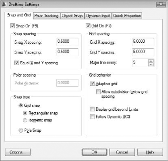
The Snap and Grid tab of the Drafting Settings dialog box appears, as shown in Figure 3-3. (In AutoCAD LT's dialog box there is no Follow Dynamic UCS option.)
Change the values in the dialog box, as shown in Figure 3-3:
Snap On: Selected
Snap constrains your crosshairs to moving in an invisible grid of equally spaced points (0.5 [10] units apart in this case).
Grid On: Selected
Grid displays a visible grid of little dots on the screen (5 [100] units apart in this case), which you can use as reference points. The grid doesn't appear on printed drawings.
Snap X Spacing: 0.5 [10]
Snap Y Spacing: 0.5 [10]
Grid X Spacing: 5 [100]
Grid Y Spacing: 5 [100]
Click OK.
You see some grid dots, 5 [100] units apart, in the drawing area. If you move your mouse around and watch the coordinate display area on the status bar, you notice that it moves in 0.5-unit [10-unit] increments.
In the Menu Browser, choose View
AutoCAD zooms out so that the entire area defined by the limits — as indicated by the grid dots — is visible.
Click the Save button on the Quick Access toolbar or press Ctrl+S.
Because you haven't saved the drawing yet, AutoCAD opens the Save Drawing As dialog box.
Navigate to a suitable folder by choosing from the Save In drop-down list and/or double-clicking folders in the list of folders below it.
Remember where you save the file so you can go back to it later.
Type a name in the File Name box and click Save.
For example, type Detail or My Plate is Base.
Depending on your Windows Explorer settings, you may or may not see the
.dwgextension in the File Name edit box. In any case, you don't need to type it. AutoCAD adds it for you.AutoCAD saves the new DWG file to the folder you specified.
Whew — that was more work than digging a post hole — and all just to set up a simple drawing! Chapter 4 goes into more detail about drawing setup and describes why all these gyrations are necessary.
With a properly set up drawing, you're ready to draw some objects. In this example, you use the RECTANG command to draw a steel base plate and column, the CIRCLE command to draw an anchor bolt, and the POLYGON command to draw a hexagonal nut. (Both the RECTANG and POLYGON commands create polylines — objects that contain a series of straight-line segments and/or arc segments.)
AutoCAD, like most CAD programs, uses layers as an organizing principle for all the objects that you draw. Chapter 6 describes layers and other object properties in detail. In this example, you create separate layers for the base plate, column, anchor bolts, and nuts. This might seem like layer madness, but when you're doing complex drawings, you need to use a lot of layers just to keep things organized.
The following steps demonstrate how to create and use layers, as well as how to draw rectangles. You also see how to apply fillets to objects and offset them. (Chapter 6 describes layers in detail, and Chapter 8 covers the RECTANG command. Chapter 11 explains the FILLET and OFFSET commands.) Start by creating a Column layer and a Plate layer and then drawing a rectangular column on the Column layer and a square base plate on the Plate layer:
Make sure that you complete the drawing setup in the previous section of this chapter and have the drawing open in AutoCAD.
Click the Home tab on the Ribbon.
You'll find the most frequently used commands for 2D drafting tasks on the Ribbon's Home tab. (For a refresher on the contents of the other tabs, refer to the "Unraveling the Ribbon" section in Chapter 2.) Unless I direct you otherwise, look on the Home tab for the panels and buttons I specify in the following steps.
On the Layers panel, click the Layer Properties button.
The Layer Properties button is at the left side of the Layers panel and may be larger than the other buttons, depending on your screen resolution. The LAYER command starts, and AutoCAD displays the Layer Properties Manager palette.
Click the New Layer button.
AutoCAD adds a new layer to the list and gives it the default name Layer1 (see Figure 3-4).
Type a more suitable name for the layer on which you'll draw the column and press Enter.
For this example, type Column.
Click the color swatch or name (white) in the Column layer row.
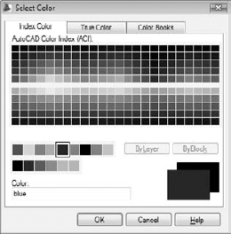
The Select Color dialog box appears (see Figure 3-5).
Click color 5 (blue) in the single, separate row to the left of the ByLayer and ByBlock buttons and click OK.
The Select Color dialog box closes, and AutoCAD changes the color of the Column layer to blue.
Repeat Steps 3 through 6 to create a new layer named Plate and set its color to 4 (cyan).
With layer Plate still highlighted, click the Set Current button (the green check mark).
Plate becomes the current layer, and everything you draw is placed on that layer until you set a different layer current.
Click Close (the 'X' at the top left corner of the palette) to close the Layer Properties Manager palette.
The Layer drop-down list on the Home tab's Layers panel displays Plate as the current layer. Now you can draw a rectangular plate on the Plate layer.
You probably already know that the RECTANG command will draw a rectangular plate for you, but for the next step, let's pretend you don't.
Open the Menu Browser, then click inside the Search menu edit box at the top of the browser and start typing RECT...
As you type into the Search box, AutoCAD starts guessing what you might be looking for. When you've typed enough letters, the command you're probably looking for appears in the main Menu Browser panel.
When "Rectangle" appears at the top of the list in the Menu Browser, simply click the command entry.
The RECTANG command starts, and AutoCAD prompts you to specify the first corner point. The command line shows:
Specify first corner point or
        [Chamfer/Elevation/Fillet/Thickness/Width]:
Click in the drawing area at the point 20,20 [500,500].
By watching the coordinate display on the dynamic input tooltip, you can see the coordinates of the current crosshairs location. Because snap is set to 0.5 [10] units, you can land right on the point 20,20 [500,500]. Picking the first corner in this location gives you enough room to work.
AutoCAD prompts:
Specify other corner point or
        [Area/Dimensions/Rotation]:
Type 36,36 [900,900] (without any spaces) and press Enter.
Make sure that the DYN button is on for this step. If it's not, AutoCAD treats an input of 36,36 as absolute coordinates — that is, 36 units above and 36 units to the right of the origin. When DYN is on, an input of 36,36 is treated as 36 units above and 36 units to the right of the last point. See Chapter 7 for more information about typing absolute and relative coordinates.
AutoCAD draws the 36 × 36 [900 × 900] rectangle, as shown in Figure 3-6. It's on the Plate layer and inherits that layer's cyan color.
You draw the column next, but first you have to change layers.
On the Layers panel click the Layer drop-down list to display the list of layers. Click Column to set it as the current layer.
Using the Layer drop-down list saves you having to open the Layer Properties Manager, select the layer, click the Set Current button, and click Close. Becoming an AutoCAD master is all about efficiency!
Press Enter to repeat the RECTANG command.
Tip
You can repeat the last command at any time by pressing Enter.
In the next steps, you create a hollow steel column.
At the
Specify first corner pointprompt, type 32,29 [800,725] and press Enter.At the
Specify other corner pointprompt, type 12,18 [300,450] and press Enter.A second rectangle is drawn in the middle of the base plate.
Next, you round the corners of the column with the FILLET command and then use OFFSET to give it some thickness.
On the Modify panel, click the Fillet button.
The FILLET command starts, and AutoCAD prompts you to select the first object. Look at the command line to see the options for this command. Apply a 2-inch [50 mm] radius fillet to all four corners as follows.
Type R and press Enter to set a new fillet radius. Type 2 [50] and press Enter.
AutoCAD again prompts you to select the first object. You could pick each of the eight lines that need to be filleted, but because the column is a continuous polyline, in this case a more efficient method is to use the FILLET command's Polyline option to fillet all four corners in one fell swoop.
Type P to choose the Polyline option, and then press Enter.
AutoCAD prompts you to select a 2D polyline.
Select the rectangle you drew in Steps 14 to 16.
All four corners of the column are rounded with a 2-inch [50 mm] radius fillet.
Next, offset the polyline to create a 3/4-inch [19 mm] thick steel column.
On the Modify panel, click the Offset button.
At the Specify Offset Distance prompt, type .75 [19] and press Enter.
At the Select Object to Offset prompt, click the rounded rectangle. At the Specify Point on Side to Offset prompt, click anywhere inside the rounded rectangle. Press Enter to complete the command.
AutoCAD offsets the selected object toward the inside of the rounded rectangle (see Figure 3-7).
Press Ctrl+S to save the drawing.
AutoCAD saves the drawing and renames the previously saved version
drawingname.bak— for example,My Plate is Base.bak. .bakis AutoCAD's extension for a backup file.


You can use the CIRCLE command to draw a 1 1/2-inch diameter anchor bolt on an Anchor Bolts layer by following these steps:
Repeat Steps 2 through 6 in the previous section to create a new layer for the anchor bolts. Give the layer the name Anchor Bolts, assign it the color 3 (green), and set it as the current layer.
The Layer drop-down on the Layers panel displays Anchor Bolts as the current layer.
On the Draw panel click the Circle button.
The CIRCLE command starts, and AutoCAD prompts you to specify the center point. The command line shows:
Specify center point for circle or [3P/2P/Ttr (tan tan
radius)]:
Click in the drawing area at point 26,26 [650,650].
AutoCAD asks you to specify the size of the circle. The command line shows:
Specify radius of circle or [Diameter]:
You decide that you want 1 1/2-inch [38 mm] diameter anchor bolts. AutoCAD is asking for a radius. Although you probably can figure out the radius of a 1 1/2-inch [38 mm] diameter circle, specify the Diameter option and let AutoCAD do the hard work.
Type D and press Enter to select the Diameter option.
AutoCAD prompts you at the command line:
Specify diameter of circle:
Type 1.5 [38] and press Enter.
AutoCAD draws the 1 1/2-inch [38 mm] diameter circle. It's on the Anchor Bolts layer and inherits that layer's green color (see Figure 3-8).

Every good bolt deserves a nut. Use the POLYGON command to draw a hexagonal shape on a Nuts layer (well, what else would you call it?). Besides showing you how to draw polygons, these steps introduce you to a couple of AutoCAD's more useful precision techniques: object snaps and ortho mode.
Repeat Steps 2 through 6 in the previous section to create a new layer for the nuts and set it as the current layer. Give the layer the name Nuts and assign it the color 1 (red).
The Layer drop-down list displays Nuts as the current layer.
Tip
You don't have to create a separate layer for every type of object that you draw. For example, you could draw both the anchor bolts and nuts on a layer called Hardware. Layer names and usage depend on industry and office practices in addition to a certain amount of individual judgment. Having too many layers is better than having too few because lumping two or more layers together is much easier than dividing the objects on one layer into two or more layers.
On the Draw panel click the Polygon button — the one that looks like a plan of the Pentagon.
The POLYGON command starts, and AutoCAD prompts you to:
Enter number of sides <4>:
Peek ahead to Figure 3-9 in order to get an idea of how the nut will look after you draw it. Four-sided nuts can be a little difficult to adjust in the real world, so I stick with the conventional hexagonal sort.
Type 6 and press Enter.
AutoCAD next prompts you for the center of the polygon:
Specify center of polygon or [Edge]:
As you move the crosshairs around near the anchor bolt, notice that AutoCAD tends to grab certain points briefly, especially on existing objects. This behavior is the result of running object snaps and tracking, which I discuss in Chapter 5. (If AutoCAD doesn't seem grabby, click the OSNAP button on the status bar until the command line shows
<Osnap on>.)Move the crosshairs over the anchor bolt you just drew.
A tooltip should show Center and pull the crosshairs to the center of the anchor bolt circle. You may also see tracking vectors across the screen from this point — you can ignore those.
Click when the tooltip reads Center — not Center-Intersection or something similar — just Center.
The POLYGON command draws regular closed polygons based on an imaginary circle; the center of this circle is the point you just picked.
AutoCAD prompts:
Enter an option [Inscribed in circle/Circumscribed
about circle] <I>:
Press Enter to accept the default Inscribed in Circle option.
Note
The Inscribed option draws a polygon whose corners touch the circumference of the imaginary circle. The Circumscribed option draws a polygon whose sides are tangent to the circumference of the circle.
AutoCAD then asks you to:
Specify radius of circle:
Turn on ortho mode by clicking the ORTHO button on the status bar until you see
<Ortho on>on the command line.Click and drag the mouse to the right so the top and bottom sides of the polygon are horizontal, but don't click yet.
Type 1.5 [38] and press Enter.
AutoCAD draws the nut, as shown in Figure 3-9. It's on the Nuts layer and inherits that layer's red color.
Occasionally, ortho and running object snaps interfere with drafting in AutoCAD. You can disable both features by clicking their status bar buttons.
Turn off ortho mode and running object snaps by clicking the ORTHO and OSNAP buttons on the status bar until they look dimmed and you see
<Ortho off>and<Osnap off>on the command line.Occasionally, ortho and running object snaps interfere with drafting in AutoCAD. Disabling them as you do in this step keeps them from being a problem.
Press Ctrl+S to save the drawing.

Not much of a base plate yet, is it? But don't worry — I cover creating more nuts and bolts with editing commands later in this chapter. If your brain is feeling full, now is a good time to take a break and go look out the window. If you exit AutoCAD, just restart the program and reopen your drawing when you're ready to continue.
The example drawing in this chapter is pretty uncluttered and small, but most real CAD drawings are neither of those. Technical drawings are usually jam-packed with lines, text, and dimensions. CAD drawings often get plotted on sheets of paper that measure two to three feet on a side — that's in the hundreds of millimeters, if you're a metric maven. Anyone who owns a monitor that large probably can afford to hire a whole room of drafters and, therefore, isn't reading this book. You need to zoom and pan in your drawings — a lot. I cover zooming and panning in detail in Chapter 12. Quick definitions should suffice for now:
Zoom means changing the magnification of the display. When you zoom in, you move closer to the drawing objects so you can see detail, and when you zoom out, you move farther away so you can see more of the drawing area.
Pan means moving from one area to another without changing the magnification. If you've used the scroll bars in any application, you've panned the display.
Zooming and panning frequently lets you see the details better, draw more confidently (because you can see what you're doing), and edit more quickly (because object selection is easier when a zillion objects aren't on the screen).
Fortunately, zooming and panning in AutoCAD is as simple as it is necessary. The following steps describe how to use AutoCAD's Zoom and Pan Realtime feature, which is pretty easy to operate and provides a lot of flexibility. Chapter 12 covers additional zoom and pan options.
To zoom and pan in your drawing, follow these steps:
Right-click in a blank area of the drawing and choose Zoom from the shortcut (right-click) menu.
The Realtime option of the ZOOM command starts. The crosshairs change to a magnifying glass, and AutoCAD prompts you at the command line:
Press ESC or ENTER to exit, or right-click to display
shortcut menu.
Move the crosshairs near the middle of the screen, press and hold the left mouse button, and drag the crosshairs up and down until the base plate almost fills the screen.
As you can see, dragging up increases the zoom magnification, and dragging down decreases it.
Right-click in the drawing area to display the Zoom/Pan Realtime menu, shown in Figure 3-10, and choose Pan from the menu.
The magnifying glass cursor changes to a hand.
Click and drag to pan the drawing until the plate is more or less centered in the drawing area.
Tip
You can use the right-click menu to toggle back and forth between Zoom and Pan as many times as you like. If you get lost, choose Zoom Original or Zoom Extents to return to a recognizable view.
Right-click in the drawing area and choose Exit from the Zoom/Pan Realtime menu.
The hand cursor returns to the normal AutoCAD crosshairs.

When you have a better view of your base plate, you can edit the objects on it more easily. In the following sections, you use the ARRAY command to add more anchor bolts, the STRETCH command to change the shape of the plate, and the HATCH command to add crosshatching to the column.
Using the ARRAY command is a great way to generate a bunch of new objects from existing objects at regular angles or spacings. The array pattern can be either rectangular (that is, columns and rows of objects) or polar (in a circle around a center point, like the spokes of a wheel around its hub). In this example, you use a rectangular array to create three additional anchor bolts:
On the Modify panel click the Array button — the one with four squares.
You may need to expand the Modify panel to find Array; click the label at the bottom of the panel to open the slideout section. The ARRAY command starts, and AutoCAD displays the Array dialog box.
Select the Rectangular Array radio button.
Click the Select Objects button.
The Array dialog box temporarily disappears, and AutoCAD prompts you to select objects.
Turn off Snap mode by clicking the SNAP button on the status bar until it looks dimmed and you see
<Snap off>on the command line.Turning off Snap mode temporarily makes selecting objects easier.
Click the anchor bolt and then click the nut.
Tip
If you encounter any problems while trying to select objects, press the Esc key a couple of times to cancel the command; then restart the ARRAY command and try again.
AutoCAD continues to prompt you at the command line:
Select objects: 1 found, 2 total
Press Enter to end object selection.
The Array dialog box reappears.
Click inside the Rows text box and set the value to 2. Press Tab to move to the Columns text box and set the value to 2.
The source object is included in AutoCAD arrays. The preview shows that you've set up a rectangular array of four evenly spaced objects (see Figure 3-11).
In the Row Offset text box, type 24 [600]. Click inside the Column Offset text box and type 24 [600].
A rectangular array creates regularly spaced rows and columns. The Row Offset is the vertical distance separating the rows; Column Offset is the horizontal distance separating columns.
Click the Preview button.
Note
AutoCAD shows you what the array will look like if you accept the current settings. In AutoCAD 2009, you can pan or zoom within preview mode if you need a bigger or a more detailed view.
If anything looks wrong, click the Esc key, make changes, and preview again. When everything looks good, right-click to accept the array.
AutoCAD adds the additional objects to the drawing, as shown in Figure 3-12.
Press Ctrl+S to save the drawing.

Perfect! Except that nutbar engineer has decided the column needs to be 18 × 18 inches [450 × 450 mm] instead of 12 × 18 inches [300 × 450mm — unfortunately, there are just as many metric nutbars as imperial ones]. And that means the base plate is too small, and the anchor bolts are in the wrong place, too. If you were working on the drawing board, you'd be getting out an eraser and rubbing out all your efforts. AutoCAD to the rescue!

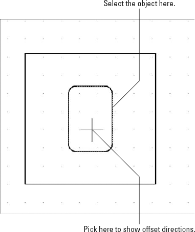
The STRETCH command is powerful but a little complicated — it can stretch or move objects, depending on how you select them. The key to using Stretch is specifying a crossing selection box properly. (Chapter 10 gives you more details about crossing boxes and how to use them with the STRETCH command.)
Follow these steps to stretch the column and base plate:
Click the Stretch button — the one with the corner of a rectangle being stretched.
The STRETCH command starts, and AutoCAD prompts you to select objects. This is one of those times (and one of those commands) that really does require you to look at the command line:
Select objects to stretch by crossing-window or
        crossing-polygon...
Select objects:
Click a point above and to the right of the upper-right corner of the plate (Point 1 in Figure 3-13).
Move the crosshairs to the left.
The pointer changes to a dashed rectangle enclosing a rectangular green area, which indicates that you're specifying a crossing box. AutoCAD prompts you at the command line:
Select objects: Specify opposite corner:
Click a point below the plate, roughly under the center of the column (Point 2 in Figure 3-13).
The crossing box must cut through the plate and column in order for the STRETCH command to work (refer to Figure 3-13).
AutoCAD prompts you at the command line:
Select objects: Specify opposite corner: 7 found
Select objects:
Press Enter to end object selection.
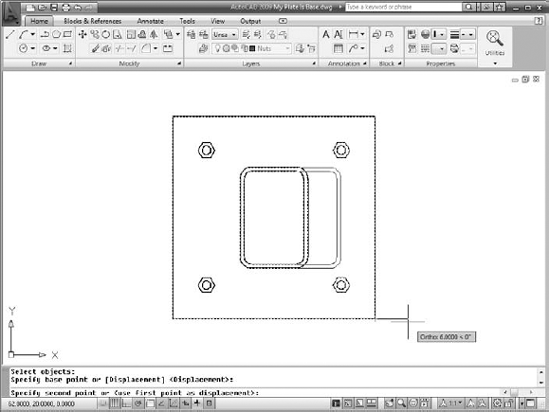
AutoCAD prompts you to specify the base point.
Turn on Snap mode, ortho mode, and running object snap mode by clicking the SNAP, ORTHO, and OSNAP buttons on the status bar until they appear highlighted.
Click the lower-right corner of the plate.
This point serves as the base point for the stretch operation. Chapter 11 describes base points and displacements in greater detail.
AutoCAD prompts you at the command line:
Specify second point or <use first point as
displacement>:
Move the crosshairs to the right until the tooltip shows a displacement of 6 [150] units to the right and then click in the drawing space (see Figure 3-14).
AutoCAD stretches the column and plate by the distance that you indicate and moves the anchor bolts that were completely inside the crossing window rectangle, as shown in Figure 3-14.
Tip
If your first stretch didn't work right, hold down the Ctrl key, type Z, and try again. Stretch is an immensely useful command — one that makes you wonder how drafters used to do it all with erasers and pencils — but it does take some practice to get the hang of those crossing boxes.
Press Ctrl+S to save the drawing.

Your final editing task is to add some crosshatching to the space between the inside and outside edges of the column to indicate that the drawing shows a section of the column. To do so, follow these steps:
Turn off Snap, Ortho, and running object snaps by clicking the SNAP, ORTHO, and OSNAP buttons on the status bar until they look dimmed.
Repeat Steps 2 through 6 from the "Drawing rectangles on the right layers" section to create a new layer named Hatch. Set its color to 2 (yellow) and make it the current layer.
On the Draw panel click the Hatch button — the one that shows the fine crosshatching inside a square.
The Hatch and Gradient dialog box appears. (If you're using AutoCAD LT, you'll notice that the box is simply called Hatch.) For more information on this dialog box, and hatching in general, refer to Chapter 12.
In the Hatch tab's Hatch and Pattern area, click the Pattern drop-down list and select ANSI31.
The ANSI31 pattern fills the selected area with an arrangement of parallel angled lines.
On the right side of the dialog box, click Add: Pick Points.
The dialog box temporarily closes.
At the Pick Internal Point prompt, pick a point between the inside and outside edges of the column. Zoom in if you need to get closer.
AutoCAD selects the two filleted polylines.
Press Enter to end object selection.
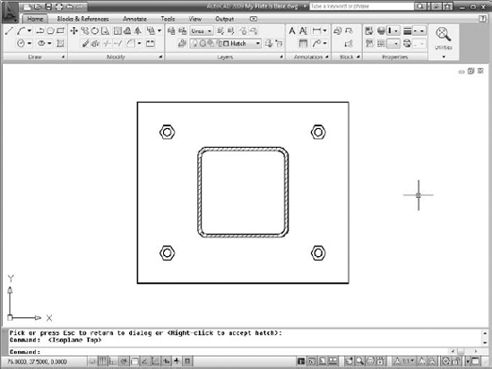
The Hatch and Gradient dialog box reappears. To check if the hatch parameters are correct, click the Preview button. It looks like the hatch pattern may be too fine.
Press Esc to return to the Hatch and Gradient dialog box.
In the Scale box, set the value to 5 and click Preview again. If it looks okay, right-click to accept the hatch pattern.
Your finished column and base plate should look like Figure 3-15.
Click the Menu Browser button and choose View
AutoCAD zooms out so that the entire area defined by the limits is visible.
Press Ctrl+S to save the drawing.
Tip
After some drawing and editing, you may wonder how you're supposed to know when to turn off or on the various status bar modes (Snap, Grid, Ortho, Osnap, and so on). You'll start to get an instinctive sense of when each mode is useful and when it gets in the way. In subsequent chapters of this book, I give you some more specific guidelines.
Looking at drawings on a computer screen and exchanging them with others via e-mail or Web sites is all well and good. But sooner or later, someone — maybe you! — will want to see a printed version. Printing drawings — or plotting, as CAD geeks like to call it — is much more complicated than printing a word processing document or a spreadsheet. That's because you have to worry about things such as drawing scale, lineweights, title blocks, and weird paper sizes. I get deeper into plotting in Chapter 16, but here's an abbreviated procedure that helps you generate a recognizable printed drawing.
Warning
The following steps show you how to plot the model space portion of the drawing. As Chapter 5 describes, AutoCAD includes a sophisticated feature called paper space layouts for creating arrangements of your drawing that you plot. These arrangements usually include a title block. Because I promised you a gentle tour of AutoCAD drafting functions, I left the paper space layout and title block issues until a bit later. When you're ready for the whole plotting enchilada, turn to Chapter 6 for information about how to set up paper space layouts and see Chapter 16 for full plotting instructions.
Follow these steps to plot a drawing:
Click the Plot button on the Quick Access toolbar.
The Quick Access toolbar is at the left end of the program's title bar, just to the right of the Menu Browser button.
AutoCAD opens the Plot dialog box.
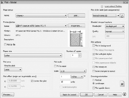
Click the More Options button (in the bottom-right corner of the dialog box, next to the Help button).
The Plot dialog box reveals additional settings, as shown in Figure 3-16.
In the Printer/Plotter area, select a printer from the Name list.
In the Paper Size area, use the drop-down list to select a paper size that's loaded in your printer or plotter.
Anything Letter size (8 1/2 × 11 inches) [A4 (210 × 297 mm)] or larger works for this example.
In the Plot Area, select Limits from the drop-down list.
This is the entire drawing area, which you specified when you set up the drawing earlier in this chapter.
In the Plot Offset area, select the Center the Plot option.
Alternatively, you can specify offsets of 0 or other amounts in order to position the plot at a specific location on the paper.
In the Plot Scale area, deselect the Fit to Paper check box and choose 1:10 from the Scale drop-down list.
1:10 is the scale used to set up the drawing (in the earlier section, "A Simple Setup"). No prizes for guessing the metric equivalent of 1:10!
In the Plot Style Table (pen assignments) area, click the drop-down list and choose
monochrome.ctb.The
monochrome.ctbplot style table ensures that all your lines appear solid black, rather than as weird shades of gray. See Chapter 16 for information about plot style tables and monochrome and color plotting.Click Yes when a question dialog box appears, asking Assign This Plotstyle Table to All Layouts?
You can leave the remaining settings at their default values (refer to Figure 3-16).
Tip
Some printers let you print closer to the edges of the sheet than others. To find out the actual printable area of your own printer, move the mouse pointer to the postage stamp–sized partial preview in the middle of the Plot dialog box and pause. A tooltip appears, listing the Paper Size and Printable Area for the printer and paper size that you selected.
Click the Preview button.
If the plot scale you entered in the Plot dialog box is out of sync with the drawing's annotation scale, a Plot Scale Confirm dialog box appears, advising you that the annotation scale is not equal to the plot scale. This drawing doesn't contain any text or dimensions, and I didn't bother making the hatch annotative, so it's fine to click Continue and generate the plot.
Note
Annotative scaling controls the printed size of text, dimensions, hatching, and other types of annotation object at plot time — as long as the drawing's annotation scale matches the plot scale. I explain annotative objects in Chapter 13.
The Plot dialog box disappears temporarily, and AutoCAD shows how the plot will look on paper. In addition, AutoCAD prompts you on the status bar:
Press pick button and drag vertically to zoom, ESC or
ENTER to exit, or right-click to display shortcut
menu.
Right-click in the preview area and choose Exit.
If the preview doesn't look right, adjust the settings in the Plot dialog box and look at the preview again until it looks right.
Click OK.
The Plot Scale Confirm dialog box pops up again. You may be tempted to click Always Continue Under These Conditions, but I recommend against that until you've gained a little familiarity with annotative objects.
The Plot dialog box closes. AutoCAD generates the plot and sends it to the printer. After generating the plot, AutoCAD displays a Plot and Publish Job Complete balloon notification from the right end of the status bar. (A Click to View Plot and Publish Details link displays more information about the plot job.)
Click the X (close) button in the Plot and Publish Job Complete balloon notification.
The balloon notification disappears.
Tip
If you're not happy with the lineweights of the lines on your plot at this point, fear not. You can use the lineweights feature (Chapter 6) or plot styles (Chapter 16) to control plotted lineweights.
Press Ctrl+S to save the drawing.
Congratulations! You successfully executed your first plot in AutoCAD. Chapter 16 tells you more — much more — about AutoCAD's highly flexible but occasionally perplexing plotting system.