
Rounding the curves with circles, arcs, splines, and clouds
Dabbling in ellipses
Dunking for donuts
Making your points
Although straight-line segments predominate in many CAD drawings, even the most humdrum, rectilinear design is likely to have a few curves. And if you're drawing Audi car bodies or Gaudí buildings, your drawings are going to contain a lot of curves! Your drawings may also have a point; in fact, they may have several points, so at the end of this chapter I fill you in on creating point objects in AutoCAD. But to begin, I show you how to use the following AutoCAD curve-drawing commands:
CIRCLE: Draws circles. (You were expecting hyperbolic paraboloids, maybe?)
ARC: Draws circular arcs — arcs with center points and fixed radii, not arcs cut from ellipses, parabolas, or some other complex curve.
ELLIPSE: Draws ellipses and elliptical arcs.
SPLINE: Draws smoothly flowing curves of a variety of shapes.
DONUT: Draws filled-in rings and circles.
REVCLOUD: Draws freeform "clouds," the most common application of which is to indicate revised areas in the drawing.
Table 9-1 lists AutoCAD's commands for drawing curvy things. It shows you the tool icons found on the Ribbon, toolbars, and menus, and gives the command name with alias (where one exists) if you like to type. It also tells you where to find or how to enter the commands using both the Ribbon in the 2D Drafting & Annotation workspace and the Draw toolbar and Draw menu in the AutoCAD Classic environment.
Table 9-1. AutoCAD Drawing Commands for Curved Objects
Button | Command | Draw Panel Button | Draw Toolbar Button | Draw Menu |
|---|---|---|---|---|
 | ARC (A) | Arc | Arc | Arc + submenu |
 | CIRCLE (C) | Circle | Circle | Circle + submenu |
 | REVCLOUD | Revision Cloud | Revision Cloud | Revision Cloud |
 | DONUT (DO) | Donut (on slideout panel) | None | Donut |
 | SPLINE (SPL) | Spline (on slideout panel) | Spline | Spline |
 | ELLIPSE (EL) | Ellipse | Ellipse | Ellipse + submenu |
 | ELLIPSE (EL), A | Ellipse Arc (on flyout button) | Ellipse Arc | Ellipse + submenu |
Note
Slideout panels are part of the Ribbon interface in AutoCAD 2009's 2D Drafting & Annotation and 3D Modeling workspaces. Slideouts are present in panels that show a small black triangle at the right end of the panel title bar. To open a slideout, you click the panel title bar (for example, Draw). The panel expands and its title bar moves to the bottom of the slideout with the small black arrow replaced by a pushpin icon. After you click a tool button, the panel closes. Click the pushpin in the title bar to pin the panel — that is, force it to stay open.
Not all drawing commands are available with every input method. For example, a few drawing commands, such as RAY, MLINE, and DONUT aren't on the classic Draw toolbar; you have to type those or choose them from the Draw menu.
Note
If you're familiar with an earlier version of AutoCAD, you may suspect that the Draw panel in AutoCAD 2009's new Ribbon interface is also missing some commands. Well, as they used to say in the '90s, the paradigm has shifted! Those commands are still there, they've just shifted around to reflect the new task-based layout. For example, block creation and insertion is still on the classic Draw menu and Draw toolbar, but those tools have moved to the Ribbon's Blocks & References panel. Similarly, the text commands are on the Ribbon's Annotate panel but are still located in their old Draw menu and Draw toolbar homes in the classic interface.
AutoCAD offers an easy and intuitive way to draw circles, and it also offers . . .other ways. The easy way is to define the center point of the circle and then to specify the radius (the default option) or diameter. You can also define a circle by choosing one of the following options of the command (for those other ways):
2-Point (2P): Draws a circle where the distance between two specified points is equal to the diameter of the circle. If you're keyboarding, you enter 2P at the command prompt to choose this option; it's spelled out as 2-Point on tooltips or 2 Points on the classic Draw menu.
3-Point (3P): Draws a circle through any three specified points.
Tangent-Tangent-Radius (Ttr): Draws a circle tangent to two existing drawing objects and a specified radius.
Tangent-Tangent-Tangent: Draws a circle tangent to three valid existing drawing objects. (By valid, I mean it's mathematically possible to construct a circle tangent to the three selected objects.) Note that you can't create this kind of circle by typing a command option at the command line, since there is no such option. This method is actually a macro and must be chosen from the Ribbon panel's tool button or from the classic Draw menu.
Figure 9-1 illustrates these six different ways of drawing circles. Whether these additional methods are useful or not depends on the kinds of drawings that you make and how geometry is defined in your industry. Get familiar with the default center point/radius method and then try the other methods to see whether they may be helpful to you. If you find yourself going around in circles, you can always draw them the default way and move them into position with other geometry.

Follow these steps to use the CIRCLE command:

The most frequently used commands in AutoCAD are found on the Ribbon's Home tab.
Set an appropriate layer current, and set other object properties that you want applied to the circles that you'll draw.
Click the Circle button on the Ribbon's Draw panel or the AutoCAD Classic Draw toolbar, or type C and press Enter.
AutoCAD starts the CIRCLE command and prompts you to specify the center point of the circle. If dynamic input is toggled on, press the down arrow on your keyboard to see the options at the crosshairs. The command line shows
Specify center point for circle or [3P/2P/Ttr (tan tan
        radius)]:
The prompts show the methods other than "center point plus radius" that you can use to draw circles in AutoCAD. (No,
tan tan radiusis not a mathematician's dance.) Look up "CIRCLE command" in the online help if you think you may have a use for these less common circle-drawing techniques.Specify the center point by clicking a point or typing coordinates.
Note
Use one of the precision techniques described in Chapter 7 if you're doing real drafting. Object snap, snap, and typing coordinates all work well for specifying the center point.
AutoCAD then prompts you to specify the circle's radius.
Specify radius of circle or [Diameter]:
Tip
Type D and press Enter if you prefer to enter the diameter rather than the radius and you've forgotten your two-times tables — or, more seriously, if the diameter is easier to type exactly than the radius is.
Specify the radius by typing a distance or clicking a point.
The first point you picked is the center. The command prompt doesn't tell you so, but if you pick a second point instead of entering a number (or typing D to invoke the Diameter option), AutoCAD interprets the distance between the first and second points as the radius value.
Arcs in AutoCAD are, quite simply, pieces of circles. As with circles, AutoCAD offers you an easy way to define arcs. Just specify three points on-screen to define the arc, easy as one-two-three. These points tell AutoCAD where to start the arc, how much to curve it, and where to end it.
Sounds pretty easy, right? So where's the problem? The trouble is that you nearly always have to specify arcs more exactly than is possible by using this method. AutoCAD helps you specify such arcs, too, but the procedure ain't easy.
You can start your arc by specifying the center of the arc or the start point. If you choose the Center option, AutoCAD prompts you for the center point first and the start point second. AutoCAD defines arcs counterclockwise, so pick a start point in a clockwise direction from the endpoint. After you specify the center and start point, AutoCAD presents several options you can choose, including the following:
Angle: This option specifies the included angle that the arc sweeps out. A 180-degree angle, for example, is a semicircle.
Length of chord: This option specifies the length of an imaginary straight line connecting the endpoints of the arc. Most people seldom or never use this option.
Endpoint: This option specifies where the arc ends. It's the default option and is often the easiest to use.
If you specify the start point as the first option, you can choose among the following three command options as well:
Center: This option prompts you for the arc's center point and then finishes with the three options listed previously.
End: This option specifies the endpoint of the arc. You then need to define the angle that the arc covers, its direction, its radius, or its center point.
Second point: This is the default option. The second point you choose isn't the endpoint; instead, it's a point on the arc that, along with the start and end points, defines how much the arc curves. After you enter the second point, you must enter an endpoint to complete the arc.
Tip
To get a feel for how these permutations can be strung together to create different arc-drawing methods, press the down arrow beside the Arc tool button on the Ribbon's Draw panel, or choose Draw

The following example shows how you draw an arc with the default start point/second point/endpoint method:

Set an appropriate layer current, and set other object properties that you want applied to the arcs that you'll draw.
Click the Arc button on the Ribbon's Draw panel (or the AutoCAD Classic Draw toolbar) or type A and press Enter.
AutoCAD starts the ARC command and prompts you to specify the first endpoint of the arc. The command line shows
Specify start point of arc or [Center]:
Specify the start point by clicking a point or typing coordinates.
AutoCAD prompts you to specify a second point on the arc.
Specify a second point on the arc by clicking a point or typing coordinates.
Tip
The second point lies somewhere along the curve of the arc. AutoCAD determines the exact curvature of the arc after you choose the final endpoint in the following step. To align the second point with an existing object, use an object snap mode.
AutoCAD prompts you to specify the other endpoint of the arc; as you move the crosshairs around, AutoCAD shows how the arc will look.
Specify the other endpoint of the arc by clicking a point or typing coordinates.
AutoCAD draws the arc, as shown previously in Figure 9-2.
Warning
As you may recall, pressing Enter repeats the last command. What often throws new AutoCAD users is that Enter does not repeat the options of the last command. If you go through the command prompts or the Draw menu to draw an arc using the Center, Start, End option, for example, pressing Enter isn't going to repeat that method — it's going to repeat the ARC command in its default form, and the three points you pick probably won't give you the arc you meant to draw. Bottom line: Watch the command line!
In case you've forgotten your ninth-grade math, an ellipse is like a squished circle. Mathematically, an ellipse is defined by a major (long) axis and a minor (short) axis. These axes determine the ellipse's length, width, and degree of curvature. An elliptical arc is an arc cut from an ellipse.
The AutoCAD ELLIPSE command provides a straightforward way of drawing an ellipse: You specify the two endpoints of one of its axes and then specify an endpoint on the other axis. But like the ARC command, the ELLIPSE command offers a bunch of other options:
Arc: This option generates an elliptical arc, not a full ellipse. You define an elliptical arc just as you do a full ellipse. The following methods for creating an ellipse apply to either.
Center: This option requires that you define the center of the ellipse and then the endpoint of an axis. You can then either enter the distance of the other axis or specify that a rotation around the major axis defines the ellipse. If you choose the latter, you can enter (or drag the ellipse to) a specific rotation for the second axis that, in turn, completely defines the ellipse.
Rotation: With this option, you specify an angle which defines the curvature of the ellipse — small angles make fat ellipses (0 degrees creates a circle, in fact), and large angles make skinny ellipses. The name of the option, Rotation, has something to do with rotating an imaginary circle around the first axis. If you can figure out the imaginary circle business, you have a better imagination than I do.
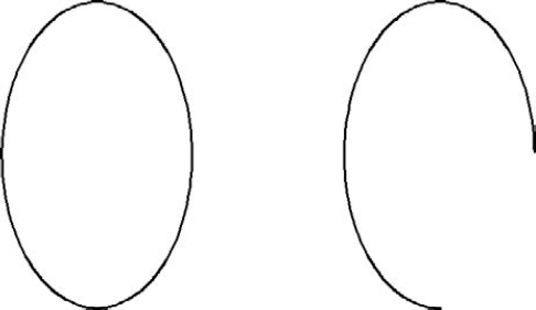
The following command line example creates an ellipse by using the default endpoints of the axes method. Figure 9-3 shows an ellipse and an elliptical arc.
Command: ELLIPSE
Specify axis endpoint of ellipse or [Arc/Center]: pick or
          type the first endpoint of one axis
Specify other endpoint of axis: pick or type the other
          endpoint of one axis
Specify distance to other axis or [Rotation]: pick or type
          the endpoint of the other axis
Tip
You can create elliptical arcs (as opposed to the circular arcs that the AutoCAD ARC command draws) by using the Arc option of the ELLIPSE command; it's perfect for drawing those cannonball trajectories! Alternatively, you can draw a full ellipse and use the TRIM or BREAK command to cut a piece out of it.
Most people use CAD programs for precision drawing tasks: straight lines, carefully defined curves, precisely specified points, and so on. AutoCAD is not the program to free your inner artist — unless your inner artist is Mondrian. Nonetheless, even meticulously created CAD drawings sometimes need freeform curves. The AutoCAD spline object is just the thing for the job.
You can use AutoCAD splines in two ways:
Eyeball the location and shape of the curve and don't worry too much about getting it just so. That's the freeform, sketchy, not-too-precise approach that I describe here.
Specify their control points and curvature characteristics precisely.
Note
Beneath their easygoing, informal exterior, AutoCAD splines are really highly precise, mathematically-defined entities called NURBS curves (NonUniform Rational B-Spline curves). Mathematicians and some mechanical and industrial designers care a lot about the precise characteristics of the curves they work with. For those people, the AutoCAD SPLINE and SPLINEDIT commands include a number of advanced options. Look up "spline curves" in the AutoCAD online help if you need precision in your splines.
Drawing splines is straightforward, if you ignore the advanced options. The following procedure draws a freeform curve with the SPLINE command:

Set an appropriate layer current, and set other object properties that you want applied to the spline segments that you'll draw.
Click the Spline button on the Ribbon's Draw panel (or the AutoCAD Classic Draw toolbar) or type SPL and press Enter.
AutoCAD starts the SPLINE command and prompts you to specify the first endpoint of the spline. The command line shows:
Specify first point or [Object]:
Specify the start point by clicking a point or typing coordinates.
AutoCAD prompts you to specify additional points:
Specify next point:
Specify additional points by clicking or typing coordinates.
After you pick the second point, press the down-arrow key to display additional options at the dynamic input tooltip. (Enable dynamic input at the status bar if you need to.) The command line shows
Specify next point or [Close/Fit tolerance] <start
        tangent>:
Tip
Because you're drawing a freeform curve, you usually don't need to use object snaps or other precision techniques when picking spline points.
Press Enter after you've chosen the final endpoint of your spline.
AutoCAD prompts you to specify tangent lines for each end of the spline:
Specify start tangent:
Specify end tangent:
Note
The
Specify start tangentandSpecify end tangentprompts can control the curvature of the start points and endpoints of the spline. In most cases, just pressing Enter at both prompts to accept the default tangents works fine.Press Enter twice to accept the default tangent directions.
AutoCAD draws the spline.
Figure 9-4 shows some examples of splines.

Tip
After you've drawn a spline, you can grip edit it to adjust its shape. See Chapter 10 for information about grip editing. If you need finer control over spline editing, look up the SPLINEDIT command in the AutoCAD online help.
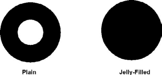
A donut in AutoCAD is another special type of polyline object that you create with (what else?) the DONUT command. (The rectangles and regular polygons I show you in Chapter 8 are also polyline objects.) Creating a donut is a simple way to define a single object that consists of two concentric circles with the space between them filled.
When you start the DONUT command, AutoCAD prompts you for the inside diameter and the outside diameter — the size of the hole and the size of the donut — as measured across their widest points. After you've entered these values, AutoCAD prompts you for the center point of the donut. But one donut is rarely enough, so AutoCAD keeps prompting you for additional center points until you press Enter (the AutoCAD equivalent of saying, "no, really, I'm full now!").
The following example draws a regulation-size donut, with a 1.5-inch hole and 3.5-inch outside diameter.
Command:DONUTSpecify inside diameter of donut <0.5000>:1.5Specify outside diameter of donut <1.0000>:3.5Specify center of donut or <exit>: pick or type the center point of one or more donuts
Tip
You can use the DONUT command to create a filled circle — also known as a jelly-filled donut. Just specify an inside diameter of 0. Figure 9-5 shows both kinds of donuts.
It's customary in many industries to submit a set of drawings at different project milestones or stages of completion and then submit them again later with revisions — corrections, clarifications, and requested changes. Usually, the recipients like to locate changed stuff easily, and a common drafting convention in many industries is to call attention to revised items by drawing freeform clouds around them. The REVCLOUD command makes quick work of drawing such clouds.
Drawing revision clouds is easy, after you understand that you click only once in the drawing area. That one click defines the starting point for the cloud's perimeter. After that, you simply move the crosshairs around, and the cloud takes shape. When you return to near the point that you clicked in the beginning, AutoCAD automatically closes the cloud.
The following command line example shows you how to draw a revision cloud. Figure 9-6 shows what revision clouds look like.
Command:REVCLOUDMinimum arc length: 0.5000 Maximum arc length: 0.5000 Style: Normal Specify start point or [Arc length/Object/Style] <Object>:pick a point along the perimeter of your future cloudGuide crosshairs along cloud path...sweep the crosshairs around to define the cloud's perimeter
You don't need to click again. Simply move the crosshairs around without clicking. AutoCAD draws the next arc segment of the cloud when your crosshairs reach the minimum arc length distance from the end of the previous arc segment.
Continue moving the crosshairs around until you return to the point where you clicked first.

It's a good idea to put revision clouds on their own layer so that you can choose to plot with or without the clouds visible.
You'll probably find it easier to control the shape of revision clouds if you turn off ortho mode before you start the command.
You may need to add a triangle and number, as shown in Figure 9-6, to indicate the revision number. A block with an attribute is a good way to handle this requirement: Chapter 17 covers blocks and attributes.
Note
If the revision cloud's arcs are too small or too large, erase the cloud, restart the REVCLOUD command, and use the command's Arc Length option to change the minimum and maximum arc lengths. The default minimum and maximum lengths are 0.5 (or 15 in metric drawings) multiplied by the DIMSCALE (DIMension SCALE) system variable setting. If you make the minimum and maximum lengths equal (which is the default), the lobes will be approximately equal in size. If you make them unequal, there will be more variation in lobe size — you'll get fluffier clouds. Fortunately, all of these options are more than most non-meteorologists will need. If you set DIMSCALE equal to the drawing scale factor (see Chapter 4), REVCLOUD should do a pretty good job of guessing reasonable default arc lengths.
I thought about not covering points in this book, but I didn't want you complaining that AutoCAD 2009 For Dummies is pointless.
Warning
The word point describes two different things in AutoCAD:
A location in the drawing that you specify (by typing coordinates or clicking with the mouse)
An object that you draw with the POINT command
Throughout this chapter and most of the book, I tell you to specify points — that's the location meaning. This section tells you how to draw point objects.
A point object in AutoCAD can serve two purposes:
Points often identify specific locations in your drawing to other people who look at the drawing. A point can be something that displays on the screen, either as a tiny dot or as another symbol, such as a cross with a circle around it.
You can use points as precise object snap locations. Think of them as construction points. For example, when you're laying out a new building, you might draw point objects at some of the engineering survey points and then snap to those points as you sketch the building's shape with the PLINE command. You use the Node object snap mode to snap to AutoCAD point objects.
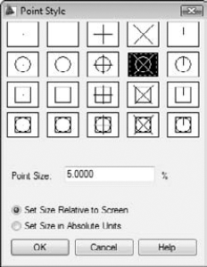
What makes AutoCAD point objects complicated is their almost limitless range of display options, provided to accommodate the two different kinds of purposes just described (and possibly some others that I haven't figured out yet). You use the Point Style dialog box, shown in Figure 9-7, to specify how points should look in the current drawing.
You can access the Point Style dialog box from the Menu Browser (2D Drafting & Annotation workspace) or the classic menu bar (AutoCAD Classic) by choosing Format
Warning
The first choice, a single-pixel dot, is hard to see on the screen, and the second choice, invisible (a stealth point?), is impossible to see. Avoid these choices if you want your point objects to show up on the screen and on plots. The single-pixel dot, which is the default display style, works well if you use point objects as object snap locations and don't want obtrusive points on plots.
The remaining settings in the Point Style dialog box control the size at which points appear on the screen at different zoom resolutions. The default settings often work fine, but if you're not satisfied with them, click the Help button in the dialog box to find out how to change them.
After you specify the point style, placing points on-screen is easy; the following example shows you how.
Command: POINT
Current point modes: PDMODE=0 PDSIZE=0.0000
Specify a point: pick or type the coordinates of a
           location in the drawing
Note
The PDMODE and PDSIZE items listed in the command window are system variables that correspond to the point display mode and display size options in the Point Style dialog box. If you want to know exactly how the system variables correspond to the dialog box choices, you have all the makings of a successful CAD nerd. Click the Help button in the Point Style dialog box to find out more (about the system variables — not about yourself).
Tip
How many points you make depends on how you start the command. If you type POINT (or its alias PO) and press Enter, AutoCAD creates a single point object and returns to the command prompt. Choosing Point from the classic Draw toolbar keeps drawing points everywhere you pick on-screen; you must press Esc to stop. Finally, starting the command from the Ribbon's Draw panel or the classic Draw menu gives you choices of single or multiple points, as well as two commands that do their work by creating point objects: DIVIDE and MEASURE. Those two useful commands can help you in laying out drawing objects — look them up in the index of the online help for more information.