Internetworking Basics
Before I explore internetworking models and the specifications of the OSI reference model, you have to understand the big picture and learn the answer to this key question: why is it so important to learn Cisco internetworking?
Networks and networking have grown exponentially over the past 15 years—understandably so. They've had to evolve at light speed just to keep up with huge increases in basic, mission-critical user needs, such as sharing data and printers, as well as more advanced demands, such as videoconferencing. Unless everyone who needs to share network resources is located in the same office area (an increasingly uncommon situation), the challenge is to connect the relevant networks so all users can share the networks' wealth.
Addressing
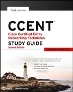
Starting with a look at Figure 1.1, you get a picture of a basic local area network (LAN) that's connected using a hub. This network is actually one collision domain and one broadcast domain—but no worries if you have no idea what this means because I'm going to talk about both collision and broadcast domains so much throughout this whole chapter that you'll probably even dream about them!
FIGURE 1.1 The basic network
Okay, about Figure 1.1—how would you say the PC named Bob communicates with the PC named Sally? Well, they're both on the same LAN connected with a multiport repeater (a hub). Does Bob just send out a data message, “Hey Sally, you there?” or does Bob use Sally's Internet Protocol (IP) address and put things more like, “Hey 192.168.0.3, are you there?” I hope you picked the IP address option, but even if you did, the news is still bad—both answers are wrong! Why? Because Bob is actually going to use Sally's Media Access Control (MAC) address (known as a hardware address), which is burned right into the network card of Sally's PC, to get ahold of her.
Great, but how does Bob get Sally's MAC address since Bob knows only Sally's name and doesn't even have her IP address yet? Bob is going to start with name resolution (hostname to IP address resolution), something that's usually accomplished using Domain Name Service (DNS). And of note, if these two are on the same LAN, Bob can just broadcast to Sally asking her for the information (no DNS needed)—welcome to Microsoft Windows!
Here's an output from a network analyzer depicting a simple name resolution process from Bob to Sally:
    Source   Destination    Protocol    Info
192.168.0.2  192.168.0.255 NBNS Name   query  NB SALLY<00>
As I already mentioned, since the two hosts are on a local LAN, Windows (Bob) will just broadcast to resolve the name Sally (the destination 192.168.0.255 is a broadcast address), and Sally will let Bob know her address was 192.16.0.3 (analyzer output not shown). Let's take a look at the rest of the information:
EthernetII,Src:192.168.0.2(00:14:22:be:18:3b),Dst:Broadcast
 (ff:ff:ff:ff:ff:ff)
What this output shows is that Bob knows his own MAC address and source IP address but not Sally's IP address or MAC address, so Bob sends a broadcast address of all fs for the MAC address (a Data Link layer broadcast) and an IP LAN broadcast of 192.168.0.255. Again, don't freak—you're going to learn all about broadcasts in Chapter 3, “IP Subnetting, Troubleshooting IP, and Introduction to NAT.”
Now Bob has to broadcast on the LAN to get Sally's MAC address so he can finally communicate to her PC and send data:
Source     Destination Protocol Info
192.168.0.2 Broadcast  ARP Who has 192.168.0.3? Tell 192.168.0.2
Next, check out Sally's response:
Source      Destination   Protocol Info
192.168.0.3 192.168.0.2   ARP 192.168.0.3 is at 00:0b:db:99:d3:5e
192.168.0.3 192.168.0.2  NBNS Name query response NB 192.168.0.3
Sweet—Bob now has both Sally's IP address and her MAC address! Both are listed as the source address at this point because this information was sent from Sally back to Bob. So, finally, Bob has all the goods he needs to communicate with Sally. And just so you know, I'm going to tell you all about Address Resolution Protocol (ARP) and show you exactly how Sally's IP address was resolved to a MAC address a little later in Chapter 6, “IP Routing.”
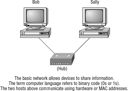
To complicate things further, it's also likely that at some point you'll have to break up one large network into a bunch of smaller ones because user response times will have dwindled to a slow crawl as the network grew and grew. And with all that growth, your LAN's traffic congestion will have reached epic proportions. The answer to this problem is breaking up that really big network into a number of smaller ones—something called network segmentation. You do this by using devices like routers, switches, and bridges. Figure 1.2 shows a network that's been segmented with a switch so each network segment connected to the switch is now a separate collision domain. But make note of the fact that this network is still one broadcast domain.
FIGURE 1.2 A switch can replace the hub, breaking up collision domains.
Keep in mind that the hub used in Figure 1.2 just extended the one collision domain from the switch port. Here's a list of some of the things that commonly cause LAN traffic congestion:
- Too many hosts in a collision or broadcast domain
- Broadcast storms
- Too much multicast traffic
- Low bandwidth
- Adding hubs for connectivity to the network
- A bunch of ARP broadcasts
Take another look at Figure 1.2. Did you notice that I replaced the main hub from Figure 1.1 with a switch? Whether you did or didn't, I did that because hubs don't segment a network; they just connect network segments. Basically, it's an inexpensive way to connect a couple of PCs, which is great for home use and troubleshooting, but that's about it!
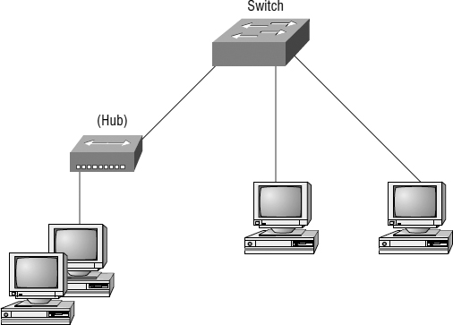
Now, routers are used to connect networks and route packets of data from one network to another. Cisco became the de facto standard of routers because of its high-quality router products, great selection, and fantastic service. Routers, by default, break up a broadcast domain—the set of all devices on a network segment that hear all the broadcasts sent on that segment. Figure 1.3 shows a router in our little network that creates an internetwork and breaks up broadcast domains.
FIGURE 1.3 Routers create an internetwork.
The network in Figure 1.3 is a pretty cool network. Each host is connected to its own collision domain, and the router has created two broadcast domains. And don't forget that the router provides connections to wide area network (WAN) services as well! The router uses something called a serial interface for WAN connections, specifically, a V.35 physical interface on a Cisco router.
Breaking up a broadcast domain is important because when a host or server sends a network broadcast, every device on the network must read and process that broadcast—unless you have a router. When the router's interface receives this broadcast, it can respond by basically saying, “Thanks, but no thanks,” and discard the broadcast without forwarding it on to other networks. Even though routers are known for breaking up broadcast domains by default, it's important to remember that they break up collision domains as well.
There are two advantages of using routers in your network.
- They don't forward broadcasts by default.
- They can filter the network based on layer 3 (Network layer) information (like the IP address).
Four router functions in your network can be listed as follows:
- Packet switching
- Packet filtering
- Internetwork communication
- Path selection
Remember, basically, that routers are really switches; they're actually what are called layer 3 switches (I'll talk about layers later in this chapter). Unlike layer 2 switches, which forward or filter frames, routers (layer 3 switches) use logical addressing and provide what is called packet switching. Routers can also provide packet filtering by using access lists, and when routers connect two or more networks together and use logical addressing (IP or IPv6), you have what is called an internetwork. Finally, routers use a routing table (map of the internetwork) to make path selections and to forward packets to remote networks.
 In this book, I'll just talk about IP addressing. If you'd like to know more about IPv6, pick up a copy of Sybex's CCNA: Cisco Certified Network Associate Study Guide, 7th Edition. There's a whole chapter on IPv6.
Conversely, layer 2 switches, the ones we usually call just plain switches, aren't used to create internetworks because they do not break up broadcast domains by default; they're employed to add functionality to a network LAN. The main purpose of these switches is to make a LAN work better—to optimize its performance—providing more bandwidth for the LAN's users. And these switches don't forward packets to other networks, as routers do. Instead, they only “switch” frames from one port to another within the switched network. Okay, you may be thinking, “Wait a minute, what are frames and packets?” I'll tell you all about them later in this chapter, I promise!
By default, switches break up collision domains. Collision domain is an Ethernet term used to describe a network scenario in which one device sends a packet on a network segment and every other device on the same segment is forced to pay attention to it. If, at the same time, a different device tries to transmit, a collision occurs, and both devices must retransmit—one at a time. Not very efficient! This situation is typically found in a hub environment, where each host segment connects to a hub that represents only one collision domain and only one broadcast domain. By contrast, each and every port on a switch represents its own collision domain.
Switches create separate collision domains within a single broadcast domain. Routers provide a separate broadcast domain for each interface.
The term bridging was introduced before routers and hubs were implemented, so it's pretty common to hear people referring to switches as bridges. That's because bridges and switches basically do the same thing—break up collision domains on a LAN (in reality, you cannot buy a physical bridge these days, only LAN switches, but they use bridging technologies, so Cisco still calls them multiport bridges at times).
So, what this means is that a switch is basically just a multiple-port bridge with more brainpower, right? Well, pretty much, but there are differences. Switches do provide a bridging function, but they do so with greatly enhanced management ability and features. Plus, most of the time, bridges had only 2 or 4 ports. Yes, you could get your hands on a bridge with up to 16 ports, but that's nothing compared to the hundreds of ports available on some switches!
You would use a bridge in a network to reduce collisions within broadcast domains and to increase the number of collision domains in your network. Doing this provides more bandwidth for users. And keep in mind that using hubs in your Ethernet network can contribute to congestion. As always, plan your network design carefully!
Figure 1.4 shows how a network would look with all these internetwork devices in place. Remember that not only will the router break up broadcast domains for every LAN interface, it will break up collision domains as well.
FIGURE 1.4 Internetworking devices
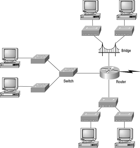
When you looked at Figure 1.4, did you notice that the router is found at center stage and that it connects each physical network together? I have to use this layout because of the older technologies involved—bridges and hubs.
On the top internetwork in Figure 1.4, you'll notice that a bridge was used to connect the hubs to a router. The bridge breaks up collision domains, but all the hosts connected to both hubs are still crammed into the same broadcast domain. Also, the bridge created only two collision domains, so each device connected to a hub is in the same collision domain as every other device connected to that same hub. This is actually pretty lame, but it's still better than having one collision domain for all hosts.
Notice something else: the three interconnected hubs at the bottom of the figure also connect to the router. This setup creates one collision domain and one broadcast domain and makes the bridged network, with its two collision domains, look much better indeed!
Although bridges/switches are used to segment networks, they will not isolate broadcast or multicast packets.
The best network connected to the router is the LAN switch network on the left. Why? Because each port on that switch breaks up collision domains. But it's not all good—all devices are still in the same broadcast domain. Do you remember why this can be a really bad thing? Because all devices must listen to all broadcasts transmitted, that's why. And if your broadcast domains are too large, the users have less bandwidth and are required to process more broadcasts. Network response time eventually will slow to a level that could cause office riots.
Once I have only switches in the example network, things change a lot! Figure 1.5 shows the network that is typically found today.
FIGURE 1.5 Switched networks creating an internetwork

Here I've placed the LAN switches at the center of the network world, and the routers are connecting the logical networks. If I implemented this kind of setup, I've created Virtual LANs (VLANs), something that you don't have to worry about in the ICND1 objectives. VLANs are covered in depth in CCNA: Cisco Certified Network Associate Study Guide, Seventh Edition (Sybex, 2011). But it is really important to understand that even in a switched network, you still need a router to provide your inter-VLAN communication, or internetworking. Don't forget that!
Obviously, the best network is one that's correctly configured to meet the business requirements of the company it serves. The best network design is one in which LAN switches with routers are used and correctly placed in the network. This book will help you understand the basics of routers and switches so you can make good, informed decisions on a case-by-case basis.
Let's go back to Figure 1.4 again. Look at the figure. How many collision domains and broadcast domains are in this internetwork? I hope you answered nine collision domains and three broadcast domains! The broadcast domains are definitely the easiest to see because only routers break up broadcast domains by default. And since there are three connections, that gives you three broadcast domains. But do you see the nine collision domains? Just in case that's a no, I'll explain. The all-hub network is one collision domain; the bridge network equals three collision domains. Add in the switch network of five collision domains—one for each switch port—and you have a total of nine.
Now, in Figure 1.5, each port on the switch is a separate collision domain, and each VLAN is a separate broadcast domain. But you still need a router for routing between VLANs. How many collision domains do you see here? I'm counting 10—remember that connections between the switches are considered a collision domain!
So, now that you've gotten an introduction to internetworking and the various devices that live in an internetwork, it's time to head into internetworking models.
![]() Real World Scenario
Real World Scenario
Should I Replace my Existing 10/100mbps switches?
You're a network administrator at a large company in San Jose. The boss comes to you and says that he got your requisition to buy all new switches and is not sure about approving the expense; do you really need it?
Well, if you can, absolutely! The newest switches really add a lot of functionality to a network that older 10/100 Mbps switches just don't have (yes, five-year-old switches are considered just plain old today). But most of us don't have an unlimited budget to buy all new gigabit switches. 10/100 Mbps switches can still create a nice network–that is, of course, if you design and implement the network correctly–but you'll still have to replace these switches eventually.
So, do you need 1Gbps or better switch ports for all your users, servers, and other devices? Yes, you absolutely need new higher-end switches! With the new Windows networking stack and the IPv6 revolution shortly ahead of us, the server and hosts are no longer the bottlenecks of our internetworks–our routers and switches are! We need at a minimum gigabit to the desktop and on every router interface; 10Gbps would be better, or even higher if you can afford it.
So, go ahead! Put that requisition in to buy all new switches.
Now that you've gotten an introduction to internetworking and the various devices that live in an internetwork, it's time to head into internetworking models.