The IP Routing Process
The IP routing process is fairly simple and doesn't change, regardless of the size of your network. For an example, I'll use Figure 6.2 to describe step-by-step what happens when Host_A wants to communicate with Host_B on a different network.
FIGURE 6.2 IP routing example using two hosts and one router

In this example, a user on Host_A pings Host_B's IP address. Routing doesn't get simpler than this, but it still involves a lot of steps. Let's work through them.
- Internet Control Message Protocol (ICMP) creates an echo request payload (which is just the alphabet in the data field).
- ICMP hands that payload to Internet Protocol (IP), which then creates a packet.
At a minimum, this packet contains an IP source address, an IP destination address, and a Protocol field with 01h. (Remember that Cisco likes to use 0x in front of hex characters, so this could look like 0x01.) That tells the receiving host to whom it should hand the payload when the destination is reached—in this example, ICMP.
- Once the packet is created, IP determines whether the destination IP address is on the local network or a remote one.
Since IP determines that this is a remote request, the packet needs to be sent to the default gateway so it can be routed to the remote network.
- The Registry in Windows is parsed to find the configured default gateway.
- The default gateway of host 172.16.10.2 (Host_A) is configured to 172.16.10.1.
For this packet to be sent to the default gateway, the hardware address of the router's interface Ethernet 0 (configured with the IP address of 172.16.10.1) must be known. Why? So, the packet can be handed down to the Data Link layer, framed, and sent to the router's interface that's connected to the 172.16.10.0 network. Because hosts communicate only via hardware addresses on the local LAN, it's important to recognize that for Host_A to communicate to Host_B, it has to send packets to the Media Access Control (MAC) address of the default gateway on the local network.
 MAC addresses are always local on the LAN and never go through and past a router.
6. Next, the Address Resolution Protocol (ARP) cache of the host is checked to see whether the IP address of the default gateway has already been resolved to a hardware address.
- If it has, the packet is then free to be handed to the Data Link layer for framing. (The hardware destination address is also handed down with that packet.) To view the ARP cache on your host, use the following command:
C:>arp -a Interface: 172.16.10.2 -- 0×3 Internet Address Physical Address Type 172.16.10.1 00-15-05-06-31-b0 dynamic - If the hardware address isn't already in the ARP cache of the host, an ARP broadcast is sent out onto the local network to search for the hardware address of 172.16.10.1. The router responds to the request and provides the hardware address of Ethernet 0, and the host caches this address.
7. Once the packet and destination hardware address are handed to the Data Link layer, the LAN driver is used to provide media access via the type of LAN being used (in this example, Ethernet).
A frame is then generated, encapsulating the packet with control information. Within that frame are the hardware destination and source addresses plus, in this case, an Ether-Type field that describes the Network layer protocol that handed the packet to the Data Link layer—in this instance, IP. At the end of the frame is something called a Frame Check Sequence (FCS) field that houses the result of the cyclic redundancy check (CRC). The frame would look something like what I've detailed in Figure 6.3. It contains Host_A's hardware (MAC) address and the destination hardware address of the default gateway. It does not include the remote host's MAC address—remember that!
FIGURE 6.3 Frame used from Host_A to the Lab_A router when Host_B is pinged
8. Once the frame is completed, it's handed down to the Physical layer to be put on the physical medium (in this example, twisted-pair wire) one bit at a time.
9. Every device in the collision domain receives these bits and builds the frame. They each run a CRC and check the answer in the FCS field. If the answers don't match, the frame is discarded.
- If the CRC matches, then the hardware destination address is checked to see whether it matches too (which, in this example, is the router's interface Ethernet 0).
- If it's a match, then the Ether-Type field is checked to find the protocol used at the Network layer.
10. The packet is pulled from the frame, and what is left of the frame is discarded. The packet is handed to the protocol listed in the Ether-Type field—it's given to IP.
11. IP receives the packet and checks the IP destination address. Since the packet's destination address doesn't match any of the addresses configured on the receiving router itself, the router will look up the destination IP network address in its routing table.
12. The routing table must have an entry for the network 172.16.20.0 or the packet will be discarded immediately and an ICMP message will be sent back to the originating device with a destination network unreachable message.
13. If the router does find an entry for the destination network in its table, the packet is switched to the exit interface—in this example, interface Ethernet 1.
The following output displays the Lab_A router's routing table. The C means “directly connected.” No routing protocols are needed in this network since all networks (all two of them) are directly connected.
Lab_A>sh ip route
Codes:C - connected,S - static,I - IGRP,R - RIP,M - mobile,B -
[output cut]
Gateway of last resort is not set
      172.16.0.0/24 is subnetted, 2 subnets
C        172.16.10.0 is directly connected, Ethernet0
C        172.16.20.0 is directly connected, Ethernet1
14. The router packet-switches the packet to the Ethernet 1 buffer.
15. The Ethernet 1 buffer needs to know the hardware address of the destination host and first checks the ARP cache.
- If the hardware address of Host_B has already been resolved and is in the router's ARP cache, then the packet and the hardware address are handed down to the Data Link layer to be framed. Let's take a look at the ARP cache on the Lab_A router by using the show ip arp command.
Lab_A#sh ip arp
Protocol  Address     Age(min) Hardware Addr Type   Interface
Internet  172.16.20.1   -     00d0.58ad.05f4 ARPA   Ethernet1
Internet  172.16.20.2   3     0030.9492.a5dd ARPA   Ethernet1
Internet  172.16.10.1   -     00d0.58ad.06aa ARPA   Ethernet0
Internet  172.16.10.2  12     0030.9492.a4ac ARPA   Ethernet0
The dash (-) means that this is the physical interface on the router. From the previous output, you can see that the router knows the 172.16.10.2 (Host_A) and 172.16.20.2 (Host_B) hardware addresses. Cisco routers will keep an entry in the ARP table for four hours.
If the hardware address has not already been resolved, the router will send an ARP request out E1 looking for the hardware address of 172.16.20.2. Host_B responds with its hardware address, and the packet and destination hardware addresses are both sent to the Data Link layer for framing.
16. The Data Link layer creates a frame with the destination and source hardware address, Ether-Type field, and FCS field at the end. The frame is handed to the Physical layer to be sent out on the physical medium one bit at a time.
17. Host_B receives the frame and immediately runs a CRC. If the result matches what's in the FCS field, the hardware destination address is then checked. If the host finds a match, the Ether-Type field is then checked to determine the protocol that the packet should be handed to at the Network layer—IP in this example.
18. At the Network layer, IP receives the packet and runs a CRC on the IP header. If that passes, IP then checks the destination address. Since there's finally a match made, the Protocol field is checked to find out to whom the payload should be given.
19. The payload is handed to ICMP, which understands that this is an echo request. ICMP responds to this by immediately discarding the packet and generating a new payload as an echo reply.
20. A packet is then created including the source and destination addresses, Protocol field, and payload. The destination device is now Host_A.
21. IP then checks to see whether the destination IP address is a device on the local LAN or on a remote network. Since the destination device is on a remote network, the packet needs to be sent to the default gateway.
22. The default gateway IP address is found in the Registry of the Windows device, and the ARP cache is checked to see whether the hardware address has already been resolved from an IP address.
23. Once the hardware address of the default gateway is found, the packet and destination hardware addresses are handed down to the Data Link layer for framing.
24. The Data Link layer frames the packet of information and includes the following in the header:
- The destination and source hardware addresses
- The Ether-Type field with 0x0800 (IP) in it
- The FCS field with the CRC result in tow
25. The frame is now handed down to the Physical layer to be sent out over the network medium one bit at a time.
26. The router's Ethernet 1 interface receives the bits and builds a frame. The CRC is run, and the FCS field is checked to make sure the answers match.
27. Once the CRC is found to be okay, the hardware destination address is checked. Since the router's interface is a match, the packet is pulled from the frame, and the Ether-Type field is checked to see what protocol at the Network layer the packet should be delivered to.
28. The protocol is determined to be IP, so it gets the packet. IP runs a CRC check on the IP header first and then checks the destination IP address.
IP does not run a complete CRC as the Data Link layer does—it only checks the header for errors.
Since the IP destination address doesn't match any of the router's interfaces, the routing table is checked to see whether it has a route to 172.16.10.0. If it doesn't have a route over to the destination network, the packet will be discarded immediately.
This is the source point of confusion for a lot of administrators—when a ping fails, most people think the packet never reached the destination host. But as you see here, that's not always the case. All it takes is for just one of the remote routers to be lacking a route back to the originating host's network and—poof!—the packet is dropped on the return trip, not on its way to the host.
 Just a quick note to mention that when (if) the packet is lost on the way back to the originating host, you will typically see a request timed out message because it is an unknown error.
If the error occurs because of a known issue, such as if a route is not in the routing table on the way to the destination device, you will see a destination unreachable message. This should help you determine whether the problem occurred on the way to the destination or on the way back.
29. In this case, the router does know how to get to network 172.16.10.0—the exit interface is Ethernet 0—so the packet is switched to interface Ethernet 0.
30. The router checks the ARP cache to determine whether the hardware address for 172.16.10.2 has already been resolved.
31. Since the hardware address to 172.16.10.2 is already cached from the originating trip to Host_B, the hardware address and packet are handed to the Data Link layer.
32. The Data Link layer builds a frame with the destination hardware address and source hardware address and then puts IP in the Ether-Type field. A CRC is run on the frame, and the result is placed in the FCS field.
33. The frame is then handed to the Physical layer to be sent out onto the local network one bit at a time.
34. The destination host receives the frame, runs a CRC, checks the destination hardware address, and looks in the Ether-Type field to find out whom to hand the packet to.
35. IP is the designated receiver, and after the packet is handed to IP at the Network layer, it checks the Protocol field for further direction. IP finds instructions to give the pay-load to ICMP, and ICMP determines the packet to be an ICMP echo reply.
36. ICMP acknowledges that it has received the reply by sending an exclamation point (!) to the user interface. ICMP then attempts to send four more echo requests to the destination host.
You've just experienced Todd's 36 easy steps to understanding IP routing. The key point to understand here is that if you had a much larger network, the process would be the same. In a really big internetwork, the packet just goes through more hops before it finds the destination host.
It's super-important to remember that when Host_A sends a packet to Host_B, the destination hardware address used is the default gateway's Ethernet interface. Why? Because frames can't be placed on remote networks—only local networks. So, packets destined for remote networks must go through the default gateway.
Let's take a look at Host_A's ARP cache now.
C: >arp -a
Interface: 172.16.10.2 -- 0×3
  Internet Address      Physical Address    Type
  172.16.10.1           00-15-05-06-31-b0   dynamic
  172.16.20.1           00-15-05-06-31-b0   dynamic
Did you notice that the hardware (MAC) address that Host_A uses to get to Host_B is the Lab_A E0 interface? Hardware addresses are always local, and they never pass a router's interface. Understanding this process is as important as air to you, so carve this into your memory!
Testing Your IP Routing Understanding
I really want to make sure you understand IP routing because it's super-important. So, I'm going to use this section to test your understanding of the IP routing process by having you look at a couple of figures and answer some very basic IP routing questions.
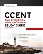
Figure 6.4 shows a LAN connected to RouterA, which is, in turn, connected via a WAN link to RouterB. RouterB has a LAN connected with an HTTP server attached.
FIGURE 6.4 IP routing example 1
The critical information you need to glean from this figure is exactly how IP routing will occur in this example. Okay—you can cheat a bit. I'll give you the answer, but then you should go back over the figure and see whether you can answer example 2 without looking at my answers.
- The destination MAC address of a frame, from HostA, will be the MAC address of the Fa0/0 interface of the RouterA router.
- The destination IP address of a packet will be the IP address of the network interface card (NIC) of the HTTP server.
- The destination port number in the segment header will have a value of 80.
That example was a pretty simple one, and it was also very to the point. One thing to remember is that if multiple hosts are communicating to the server using HTTP, they must all use a different source port number. That is how the server keeps the data separated at the Transport layer.
Let's mix it up a little and add another internetworking device into the network and then see whether you can find the answers. Figure 6.5 shows a network with only one router but two switches.
FIGURE 6.5 IP routing example 2

What you want to understand about the IP routing process here is what happens when HostA sends data to the HTTPS server.
- The destination MAC address of a frame, from HostA, will be the MAC address of the Fa0/0 interface of the RouterA router.
- The destination IP address of a packet will be the IP address of the network interface card (NIC) of the HTTPS server.
- The destination port number in the segment header will have a value of 443.
Notice that the switches weren't used as either a default gateway or another destination. That's because switches have nothing to do with routing. I wonder how many of you chose the switch as the default gateway (destination) MAC address for HostA? If you did, don't feel bad—just take another look with that fact in mind. It's very important to remember that the destination MAC address will always be the router's interface—if your packets are destined for outside the LAN, as they were in these last two examples.
Before I move into some of the more advanced aspects of IP routing, I'll discuss ICMP in more detail, as well as how ICMP is used in an internetwork. Take a look at the network shown in Figure 6.6. Ask yourself, “What will happen if the LAN interface of Lab_C is down and Host A pings Host B?”
FIGURE 6.6 ICMP error example

Lab_C will use ICMP to inform Host A that Host B can't be reached, and it will do this by sending an ICMP destination unreachable message. The point of this figure is to help you visualize how ICMP data is routed via IP back to the originating station.
Let's look at another problem. Here's the output of a corporate router's routing table:
Corp#sh ip route
[output cut]
R    192.168.215.0 [120/2] via 192.168.20.2, 00:00:23, Serial0/0
R    192.168.115.0 [120/1] via 192.168.20.2, 00:00:23, Serial0/0
R    192.168.30.0 [120/1] via 192.168.20.2, 00:00:23, Serial0/0
C    192.168.20.0 is directly connected, Serial0/0
C    192.168.214.0 is directly connected, FastEthernet0/0
What do you see here? If I were to tell you that the corporate router received an IP packet with a source IP address of 192.168.214.20 and a destination address of 192.168.22.3, what do you think the Corp router will do with this packet?
If you said, “The packet came in on the FastEthernet 0/0 interface, but since the routing table doesn't show a route to network 192.168.22.0 (or a default route), the router will discard the packet and send an ICMP destination unreachable message back out interface FastEthernet 0/0,” you're a genius! The reason it does this is because that's the source LAN where the packet originated from.
Now, let's check out another figure and talk about the frames and packets in detail. Really, I'm not exactly chatting about anything new; I'm just making sure that you totally, completely, fully understand basic IP routing. That's because this book, and the exam objectives it's geared toward, are all about IP routing, which means you need to be all over this stuff! I'll use Figure 6.7 for the next few questions.
FIGURE 6.7 Basic IP routing using MAC and IP addresses

Referring to Figure 6.7, here's a list of all the questions you need the answers to emblazoned in your brain:
- In order to begin communicating with the Sales server, Host 4 sends out an ARP request. How will the devices exhibited in the topology respond to this request?
- Host 4 has received an ARP reply. Host 4 will now build a packet and then place this packet in the frame. What information will be placed in the header of the packet that leaves Host 4 if Host 4 is going to communicate to the Sales server?
- At last, the Lab_A router has received the packet and will send it out Fa0/0 onto the LAN toward the server. What will the frame have in the header as the source and destination addresses?
- Host 4 is displaying two web documents from the Sales server in two browser windows at the same time. How did the data find its way to the correct browser windows?
I probably should write the following in a teensy font and put them upside down in another part of the book so it would be really hard for you to cheat and peek, but since it's actually you who's going to lose out if you peek, here are your answers:
- To begin communicating with the server, Host 4 determines that this is a remote request and sends out an ARP request for the default gateway hardware address. The Lab_B router will respond with the MAC address of the Fa0/0 interface, and Host 4 will send all frames to the MAC address of the Lab_B Fa0/0 interface when sending packets to the Sales server.
- Host 4 has received an ARP reply. Host 4 will now build a packet and then place this packet in the frame. What information will be placed in the header of the packet that leaves Host 4 if Host 4 is going to communicate to the Sales server? Since I'm now talking about packets, not frames, the source address will be the IP address of Host 4, and the destination address will be the IP address of the Sales server.
- Finally, the Lab_A router has received the packet and will send it out Fa0/0 onto the LAN toward the server. What will the frame have in the header as the source and destination addresses? The source MAC address will be the Lab_A router's Fa0/0 interface, and the destination MAC address will be the Sales server's MAC address. (All MAC addresses must be local on the LAN.)
- Host 4 is displaying two web documents from the Sales server in two different browser windows at the same time. How did the data find its way to the correct browser windows? TCP port numbers are used to direct the data to the correct application window.
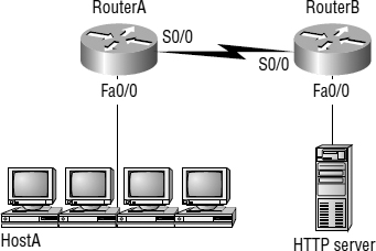
Great! But you're not quite done yet. I've got a few more questions for you before you actually get to configure routing in a real network. Ready? Figure 6.8 shows a basic network, and Host 4 needs to get email. Which address will be placed in the destination address field of the frame when it leaves Host 4?
FIGURE 6.8 Testing basic routing knowledge
The answer is that Host 4 will use the destination MAC address of the Fa0/0 interface of the Lab_B router—which I'm so sure you knew, right? Look at Figure 6.8 again: Host 4 needs to communicate with Host 1. Which OSI layer 3 source address will be placed in the packet header when it reaches Host 1?
I hope you know this. At layer 3, the source IP address will be Host 4, and the destination address in the packet will be the IP address of Host 1. Of course, the destination MAC address from Host 4 will always be the Fa0/0 address of the Lab_B router if the destination is remote, right? And since there is more than one router, you'll need a routing protocol that communicates between both of them so that traffic can be forwarded in the right direction to reach the network in which Host 1 is attached.
Okay—one more question, and you're on your way to being an IP routing genius! Again, look at Figure 6.8; Host 4 is transferring a file to the email server connected to the Lab_A router. What would be the layer 2 destination address leaving Host 4? Yes, I've asked this question more than once. But not this one: what will be the source MAC address when the frame is received at the email server?
Ideally, you answered that the layer 2 destination address leaving Host 4 will be the MAC address of the Fa0/0 interface of the Lab_B router and that the source layer 2 address that the email server will receive will be the Fa0/0 interface of the Lab_A router.
If you did, you're all set to get the skinny on how IP routing is handled in a larger network.
Configuring IP Routing
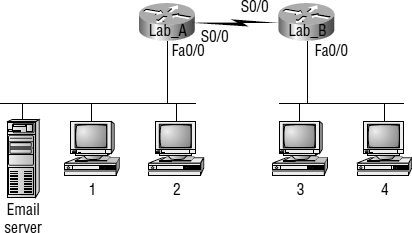
It's time to get serious and configure a real network! Figure 6.9 shows four routers: Corp, Remote1, Remote2, and Remote3. Remember that, by default, these routers know only about networks that are directly connected to them. I'll continue to use this figure and network throughout the rest of the chapters in this book.
FIGURE 6.9 Configuring IP routing
As you might guess, I've got quite a nice collection of routers for us to play with. The Corp router is a 2811 with four serial interfaces and a switch module, and remote routers 1 and 2 are 1841 routers. Remote 3 is another 2811 with a wireless interface card. I'm simply going to call the remote routers R1, R2, and R3. (Understand that you can still perform most of the commands I use in this book with older routers or with a router simulator.)
The first step for this project is to correctly configure each router with an IP address on each interface. Table 6.1 shows the IP address scheme I'm going to use to configure the network. After I go over how the network is configured, I'll cover how to configure IP routing. Each network in the table has a 24-bit subnet mask (255.255.255.0), which makes the interesting (subnet) octet the third one.
TABLE 6.1 Network addressing for the IP network
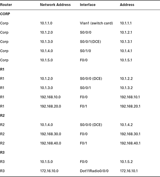
The router configuration is really a pretty straightforward process since you just need to add IP addresses to your interfaces and then perform a no shutdown on those same interfaces. It gets a tad more complex later, but for right now, let's configure the IP addresses in the network.
Corp Configuration
I need to configure five interfaces to configure the Corp router. And configuring the host-names of each router will make identification much easier. While I'm at it, why not set the interface descriptions, banner, and router passwords too? It's a really good idea to make a habit of configuring these commands on every router.
To get started, I performed an erase startup-config on the router and reloaded, so I'll start in setup mode. I choose no to entering setup mode, which will get me straight to the username prompt of the console. I'm going to configure all my routers this same way.
I need to mention one small issue before I configure the Corp router, and that is the switch card configuration. The IP address is configured on a logical interface on a switch, not a physical interface, and that interface by default is named vlan 1. Also, unlike with standalone switches, the interfaces on my switch card installed in the router are not enabled by default, so you'll see that I enable the ports I am using in this lab.
Here's how I did all that:
        -- System Configuration Dialog --


Would you like to enter the initial configuration dialog? [yes/no]: n


Press RETURN to get started!
Router>en
Router#config t
Enter configuration commands, one per line. End with CNTL/Z.
Router(config)#hostname Corp
Corp(config)#enable secret todd
Corp(config)#interface vlan 1
Corp(config-if)#description Switch Card to Core Network
Corp(config-if)#ip address 10.1.1.1 255.255.255.0
Corp(config-if)#no shutdown
Corp(config-if)#int f1/0
Corp(config-if)#description Switch Port connection to WWW Server
Corp(config-if)#no shutdown
Corp(config-if)#int f1/1
Corp(config-if)#description Switch port connection to Email Server
Corp(config-if)#no shut
Corp(config-if)#int f1/2
Corp(config-if)#description Switch port connection to DNS Server
Corp(config-if)#no shut
Corp(config-if)#int s0/0/0
Corp(config-if)#description 1st Connection to R1
Corp(config-if)#ip address 10.1.2.1 255.255.255.0
Corp(config-if)#no shut
Corp(config-if)#int s0/0/1
Corp(config-if)#description 2nd Connection to R1
Corp(config-if)#ip address 10.1.3.1 255.255.255.0
Corp(config-if)#no shut
Corp(config-if)#int s0/1/0
Corp(config-if)#description Connection to R2
Corp(config-if)#ip address 10.1.4.1 255.255.255.0
Corp(config-if)#no shut
Corp(config-if)#int fa0/0
Corp(config-if)# description Connection to R3
Corp(config-if)# ip address 10.1.5.1 255.255.255.0
Corp(config-if)#no shut
Corp(config-if)#line con 0
Corp(config-line)#password console
Corp(config-line)#login
Corp(config-line)#logging synchronous
Corp(config-line)#exec-timeout 0 0
Corp(config-line)#line aux 0
Corp(config-line)#password aux
Corp(config-line)#login
Corp(config-line)#exit
Corp(config)#line vty 0 ?
  <1-15> Last Line number
  <cr>
Corp(config)#line vty 0 15
Corp(config-line)#password telnet
Corp(config-line)#login
Corp(config-line)#exit
Corp(config)#no ip domain lookup
Corp(config)#banner motd # This is my Corp 2811 ISR Router #
Corp(config-if)#^Z
Corp#copy running-config startup-config
Destination filename [startup-config]?[enter]
Building configuration…
[OK]
Corp#
If you have a hard time understanding this configuration process, refer to Chapter 4, “Cisco's Internetworking Operating System (IOS).”
To view the IP routing tables created on a Cisco router, use the command show ip route. The command output is as follows:
Corp#sh ip route
Codes: C - connected, S - static, R - RIP, M - mobile, B - BGP
       D - EIGRP, EX - EIGRP external, O - OSPF, IA - OSPF inter area
       N1 - OSPF NSSA external type 1, N2 - OSPF NSSA external type 2
       E1 - OSPF external type 1, E2 - OSPF external type 2
       i - IS-IS, su - IS-IS summary, L1 - IS-IS level-1, L2 - IS-IS
   level-2, ia - IS-IS inter area, * - candidate default, U - per-user
   static route, o - ODR, P - periodic downloaded static route


Gateway of last resort is not set


      10.0.0.0/24 is subnetted, 1 subnets
C        10.1.1.0 is directly connected, Vlan1
Corp#
It's important to remember that only configured, directly connected networks are going to show up in the routing table. So, why is it that I see only the Vlan1 interface in the routing table? No worries—that's just because you won't see the serial interfaces come up until the other side of the links are operational. As soon as I configure the R1, R2, and R3 routers, all those interfaces should pop right up.
But did you notice the C on the left side of the output of the routing table? When you see that there, it means that the network is directly connected. The codes for each type of connection are listed at the top of the show ip route command, along with their descriptions.
In the interest of brevity, the codes will be cut in the rest of this chapter.
R1 Configuration
Now I'm ready to configure the next router—R1. To make that happen correctly, keep in mind that I have four interfaces to deal with: serial 0/0/0, serial 0/0/1, FastEthernet 0/0, and FastEthernet 0/1. So, let's make sure I don't forget to add the hostname, passwords, interface descriptions, and banner to the router configuration. As I did with the Corp router, I erased the configuration and reloaded.
Here's the configuration I used:
R1#erase start
% Incomplete command.
R1#erase startup-config
Erasing the nvram filesystem will remove all configuration files!
   Continue? [confirm][enter]
[OK]
Erase of nvram: complete
R1#reload
Proceed with reload? [confirm][enter]
[output cut]
%Error opening tftp://255.255.255.255/network-confg (Timed out)
%Error opening tftp://255.255.255.255/cisconet.cfg (Timed out)


         -- System Configuration Dialog --


Would you like to enter the initial configuration dialog? [yes/no]: n
Before moving on, I really want to discuss the preceding output with you. First, notice that the new 12.4 ISR routers will no longer take the command erase start. The router has only one command after erase that starts with s, as shown here:
Router#erase s?
startup-config
I know, you'd think that the IOS would continue to accept the command, but nope—sorry! The second thing I want to point out is that the output tells you the router is looking for a TFTP host to see whether it can download a configuration. When that fails, it goes straight into setup mode. This gives you a great picture of the Cisco router default boot sequence I talked about in Chapter 5, “Managing a Cisco Internetwork.”
Okay, let's get back to configuring the router.
Press RETURN to get started!
Router>en
Router#config t
Router(config)#hostname R1
R1(config)#enable secret todd
R1(config)#int s0/0/0
R1(config-if)#ip address 10.1.2.2 255.255.255.0
R1(config-if)#Description 1st Connection to Corp Router
R1(config-if)#no shut
R1(config-if)#int s0/0/1
R1(config-if)#ip address 10.1.3.2 255.255.255.0
R1(config-if)#no shut
R1(config-if)#description 2nd connection to Corp Router
R1(config-if)#int f0/0
R1(config-if)#ip address 192.168.10.1 255.255.255.0
R1(config-if)#description Connection to Finance PC
R1(config-if)#no shut
R1(config-if)#int f0/1
R1(config-if)#ip address 192.168.20.1 255.255.255.0
R1(config-if)#description Connection to Marketing PC
R1(config-if)#no shut
R1(config-if)#line con 0
R1(config-line)#password console
R1(config-line)#login
R1(config-line)#logging synchronous
R1(config-line)#exec-timeout 0 0
R1(config-line)#line aux 0
R1(config-line)#password aux
R1(config-line)#login
R1(config-line)#exit
R1(config)#line vty 0 ?
  <1-807> Last Line number
  <cr>
R1(config)#line vty 0 807
R1(config-line)#password telnet
R1(config-line)#login
R1(config-line)#banner motd # This is my R1 Router #
R1(config)#no ip domain-lookup
R1(config)#exit
R1#copy run start
Destination filename [startup-config]?[enter]
Building configuration…
[OK]
R1#
Let's take a look at the configuration of the interfaces.
R1#sh run | begin interface
interface FastEthernet0/0
 description Connection to Finance PC
 ip address 192.168.10.1 255.255.255.0
 duplex auto
 speed auto
!
interface FastEthernet0/1
 description Connection to Marketing PC
 ip address 192.168.20.1 255.255.255.0
 duplex auto
 speed auto
!
interface Serial0/0/0
 description 1st Connection to Corp Router
 ip address 10.1.2.2 255.255.255.0
!
interface Serial0/0/1
 description 2nd connection to Corp Router
 ip address 10.1.3.2 255.255.255.0
!
The show ip route command displays the following:
R1#show ip route
     10.0.0.0/24 is subnetted, 4 subnets
C       10.1.3.0 is directly connected, Serial0/0/1
C       10.1.2.0 is directly connected, Serial0/0/0
C       192.168.20.0 is directly connected, FastEthernet0/1
C       192.168.10.0 is directly connected, FastEthernet0/0
R1#
Notice that router R1 knows how to get to networks 10.1.3.0, 10.1.2.0, 192.168.20.0, and 192.168.10.0. I can now ping to the Corp router from R1.
R1#10.1.2.1


Type escape sequence to abort.
Sending 5, 100-byte ICMP Echos to 10.1.2.1, timeout is 2 seconds:
!!!!!
Success rate is 100 percent (5/5), round-trip min/avg/max = 1/2/4 ms
R1#
Now let's go back to the Corp router and look at the routing table.
Corp#sh ip route
[output cut]
     10.0.0.0/24 is subnetted, 4 subnets
C       10.1.3.0 is directly connected, Serial0/0/1
C       10.1.2.0 is directly connected, Serial0/0/0
C       10.1.1.0 is directly connected, Vlan1
Corp#
The R1 serial interface 0/0/0 and 0/0/1 are DCE connections, which means a clock rate needs to be set on the interface. Remember that you don't need to use the clock rate command in production. Even though this is very true, it's still imperative that you know how/when you can use it and that you understand it really well when studying for your CCNA exam!
You can see the clocking with the show controllers command.
R1#sh controllers s0/0/1
Interface Serial0/0/1
Hardware is GT96K
DCE V.35, clock rate 2000000
One last thing before I get into configuring the other remote routers: did you notice the clock rate is 2000000 under the serial interfaces of the R1 router? That's important because if you think back to when I was configuring the R1 router, you'll recall that I didn't set the clock rate. The reason I didn't is because ISR routers will autodetect a DCE-type cable and automatically configure the clock rate—a really sweet feature!
Since the serial links are showing up, you can now see three networks in the Corp routing table. And once I configure R2 and R3, you'll see two more networks in the routing table of the Corp router. The Corp router can't see either the 192.168.10.0 or 192.168.20.0 network because I don't have any routing configured yet—routers see only directly connected networks by default.
R2 Configuration
To configure R2, I'm going to do pretty much the same thing I did with the other two routers. There are three interfaces (serial 0/0/0, FastEthernet 0/0, and FastEthernet 0/1) to deal with, and again, I'll be sure to add the hostname, passwords, interface descriptions, and a banner to the router configuration.
Router>en
Router#config t
Router(config)#hostname R2
R2(config)#enable secret todd
R2(config)#int s0/0/0
R2(config-if)#ip address 10.1.4.2 255.255.255.0
R2(config-if)#description Connection to Corp Router
R2(config-if)#no shut
R2(config-if)#int f0/0
R2(config-if)#ip address 192.168.30.1 255.255.255.0
R2(config-if)#description Connection to Sales PC
R2(config-if)#no shut
R2(config-if)#int f0/1
R2(config-if)#ip address 192.168.40.1 255.255.255.0
R2(config-if)#description Connection to HR PC
R2(config-if)#no shut
R2(config-if)#line con 0
R2(config-line)#password console
R2(config-line)#login
R2(config-line)#logging sync
R2(config-line)#exec-timeout 0 0
R2(config-line)#line aux 0
R2(config-line)#password aux
R2(config-line)#login
R2(config-line)#exit
R2(config)#line vty 0 ?
  <1-807> Last Line number
  <cr>
R2(config)#line vty 0 807
R2(config-line)#password telnet
R2(config-line)#login
R2(config-line)#exit
R2(config)#banner motd # This is my R2 Router #
R2(config)#no ip domain-lookup
R2(config)#^Z
R2#copy run start
Destination filename [startup-config]?[enter]
Building configuration…
[OK]
R2#
Nice—everything was pretty straightforward. The output of the following show ip route command displays the directly connected networks of 192.168.30.0, and 192.168.40.0 and 10.1.4.0, as you can see here:
R2#sh ip route
     10.0.0.0/24 is subnetted, 3 subnets
C       192.168.30.0 is directly connected, FastEthernet0/0
C       192.168.40.0 is directly connected, FastEthernet0/1
C       10.1.4.0 is directly connected, Serial0/0/0
R2#
The Corp, R1, and R2 routers now have all their directly connected links up. But I still need to configure the R3 router.
R3 Configuration
To configure R3, I'm going to do pretty much the same thing I did with the other routers. However, there are only two interfaces (FastEthernet 0/0 and Dot11Radio0/0/0) to deal with, and again, I'll be sure to add the hostname, passwords, interface descriptions, and a banner to the router configuration.
Router>en
Router#config t
Router(config)#hostname R3
R3(config)#enable secret todd
R3(config)#int f0/0
R3(config-if)#ip address 10.1.5.2 255.255.255.0
R3(config-if)#description Connection to Corp Router
R3(config-if)#no shut
R3(config-if)#int dot11radio0/0/0
R3(config-if)#ip address 172.16.10.1 255.255.255.0
R3(config-if)#description WLAN for Mobile User
R3(config-if)#no shut
R3(config-if)#ssid ADMIN
R3(config-if-ssid)#guest-mode
R3(config-if-ssid)#authentication open
R3(config-if-ssid)#infrastructure-ssid
R3(config-if-ssid)#exit
R3(config-line)#line con 0
R3(config-line)#password console
R3(config-line)#login
R3(config-line)#logging sync
R3(config-line)#exec-timeout 0 0
R3(config-line)#line aux 0
R3(config-line)#password aux
R3(config-line)#login
R3(config-line)#exit
R3(config)#line vty 0 ?
  <1-807> Last Line number
  <cr>
R3(config)#line vty 0 807
R3(config-line)#password telnet
R3(config-line)#login
R3(config-line)#exit
R3(config)#banner motd # This is my R3 Router #
R3(config)#no ip domain-lookup
R3(config)#^Z
R3#copy run start
Destination filename [startup-config]?[enter]
Building configuration…
[OK]
R3#
Nice—everything again was pretty straightforward…except for that wireless interface. It's true, the wireless interface is really just another interface on a router, and it looks just like that in the routing table as well. But, to bring up the wireless interface, more configurations are needed than for a simple FastEthernet interface. So, check out the following output, and then I'll tell you about the special configuration needs for this wireless interface:
R3(config-if)#int dot11radio0/0/0
R3(config-if)#ip address 172.16.10.1 255.255.255.0
R3(config-if)# description WLAN for Mobile User
R3(config-if)#no shut
R3(config-if)#ssid ADMIN
R3(config-if-ssid)#guest-mode
R3(config-if-ssid)#authentication open
R3(config-if-ssid)#infrastructure-ssid
So, what you see here is that everything is pretty commonplace until you get to the SSID configuration. This is the Service Set Identifier that creates a wireless network that hosts can connect to. Unlike access points, the interface on the R3 router is actually a routed interface, which is the reason the IP address is placed under the physical interface—typically, if this was an access point only and not a router, the IP address would be placed under the Bridge-Group Virtual Interface (BVI), which is a logical management interface.
That guest-mode line means that the interface will broadcast the SSID so wireless hosts will understand that they can connect to this interface. Authentication open means just that…no authentication. (Even so, you still have to type that command in at a minimum to make the wireless interface work.) Last, the infrastructure-ssid indicates that this interface can be used to communicate to other access points, or other devices on the infrastructure, to the actual wired network itself.
Configuring DHCP on the Router
But wait, I'm not done yet—I still need to configure the DHCP pool for the wireless clients connecting to the Dot11Radio0/0/0 interface, so let's do that now.
R3#config t
R3(config)#ip dhcp pool Admin
R3(dhcp-config)#network 172.16.10.0 255.255.255.0
R3(dhcp-config)#default-router 172.16.10.1
R3(dhcp-config)#dns-server 172.16.10.2
R3(dhcp-config)#exit
R3(config)#ip dhcp excluded-address 172.16.10.1 172.16.10.10
R3(config)#
Creating DHCP pools on a router is actually a pretty simple process, and this would be the same configuration for any router you need to add a DHCP pool to. To create the DHCP server on a router, follow these steps:
- Just create the pool name.
- Add the network/subnet and the default gateway.
- Exclude any addresses you don't want handed out (like the default gateway address).
- You'd usually add a DNS server as well.
Don't forget to add your exclusions, which are addresses you don't want the DHCP server handing out as valid host IPs. These exclusions are configured from global config mode, not within the DHCP pool config. Notice, also, that you can exclude a range of addresses on one line—very convenient. In the preceding example, I excluded 172.16.10.1 through 172.16.10.10 from being assigned by the DHCP server as valid IP address to DHCP clients. You can verify the DHCP pool with the show ip dhcp binding command.
R3#sh ip dhcp binding
IP address       Client-ID/           Lease expiration        Type
                 Hardware address
172.16.10.11     0001.96AB.8538       --                      Automatic
R3#
And of course, you can verify the client with the ipconfig command on the Mobile User laptop.
PC>ipconfig /all


Physical Address................: 0001.96AB.8538
IP Address......................: 172.16.10.11
Subnet Mask.....................: 255.255.255.0
Default Gateway.................: 172.16.10.1
DNS Servers.....................: 172.16.10.2
Now that I did a basic WLAN configuration, the mobile user is connected to the wireless network. The user just can't get anywhere else yet in the internetwork! Let's fix that.
Wireless networks will be discussed in detail in Chapter 8, “Wireless Technologies.”