Ethernet Networking
Ethernet is a contention-based media access method that allows all hosts on a network to share the same bandwidth of a link. Ethernet is popular because it's readily scalable, meaning that it's comparatively easy to integrate new technologies, such as upgrading from Fast Ethernet to Gigabit Ethernet, into an existing network infrastructure. It's also relatively simple to implement in the first place, and with it, troubleshooting is reasonably straightforward. Ethernet uses both Data Link and Physical layer specifications, and this chapter will give you both the Data Link layer and Physical layer information you need to effectively implement, troubleshoot, and maintain an Ethernet network.
Collision Domain
The term collision domain is an Ethernet term that refers to a particular network scenario wherein one device sends a packet out on a network segment, thereby forcing every other device on that same physical network segment to pay attention to it. This can be bad because if two devices on one physical segment transmit at the same time, a collision event—a situation where each device's digital signals interfere with another on the wire—occurs and forces the devices to retransmit later. Collisions can have a dramatically negative effect on network performance, so they're definitely something you want to avoid!
The situation I just described is typically found in a hub environment where each host segment connects to a hub that represents only one collision domain and one broadcast domain.
Broadcast Domain
Here's the written definition: a broadcast domain refers to the set of all devices on a network segment that hear all the broadcasts sent on that segment.
Even though a broadcast domain is typically a boundary delimited by physical media like switches and routers, it can also reference a logical division of a network segment where all hosts can reach each other via a Data Link layer (hardware address) broadcast.
That's the basic story, so now let's take a look at a collision detection mechanism used in half-duplex Ethernet.
CSMA/CD
Ethernet networking uses Carrier Sense Multiple Access with Collision Detection (CSMA/CD), a protocol that helps devices share the bandwidth evenly without having two devices transmit at the same time on the network medium. CSMA/CD was created to overcome the problem of those collisions that occur when packets are transmitted simultaneously from different nodes. And trust me—good collision management is crucial, because when a node transmits in a CSMA/CD network, all the other nodes on the network receive and examine that transmission. Only bridges and routers can effectively prevent a transmission from propagating throughout the entire network!
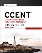
So, how does the CSMA/CD protocol work? Let's start by taking a look at Figure 1.18.
When a host wants to transmit over the network, it first checks for the presence of a digital signal on the wire. If all is clear (no other host is transmitting), the host will then proceed with its transmission. But it doesn't stop there. The transmitting host constantly monitors the wire to make sure no other hosts begin transmitting. If the host detects another signal on the wire, it sends out an extended jam signal that causes all nodes on the segment to stop sending data (think busy signal). The nodes respond to that jam signal by waiting a while before attempting to transmit again. Backoff algorithms determine when the colliding stations can retransmit. If collisions keep occurring after 15 tries, the nodes attempting to transmit will then timeout. Pretty clean!
When a collision occurs on an Ethernet LAN, the following happens:
- A jam signal informs all devices that a collision occurred.
- The collision invokes a random backoff algorithm.
- Each device on the Ethernet segment stops transmitting for a short time until their backoff timers expire.
- All hosts have equal priority to transmit after the timers have expired.
The following are the effects of having a CSMA/CD network sustaining heavy collisions:
- Delay
- Low throughput
- Congestion
 Backoff on an Ethernetnetwork is the retransmission delay that's enforced when a collision occurs. When a collision occurs, a host will resume transmission after the forced time delay has expired. After this backoff delay period has expired, all stations have equal priority to transmit data.
In the following sections, I am going to cover Ethernet in detail at both the Data Link layer (layer 2) and the Physical layer (layer 1).
Half- and Full-Duplex Ethernet
Half-duplex Ethernet is defined in the original IEEE 802.3 Ethernet; Cisco says it uses only one wire pair with a digital signal running in both directions on the wire. Certainly, the IEEE specifications discuss the process of half-duplex somewhat differently, but what Cisco is talking about is a general sense of what is happening here with Ethernet.
It also uses the CSMA/CD protocol to help prevent collisions and to permit retransmitting if a collision does occur. If a hub is attached to a switch, it must operate in half-duplex mode because the end stations must be able to detect collisions. Half-duplex Ethernet is only about 30 to 40 percent efficient as Cisco sees it because a large 100BaseT network will usually give you only 30Mbps to 40Mbps under heavy load, at most.
But full-duplex Ethernet uses two pairs of wires at the same time instead of one wire pair like half-duplex. And full duplex uses a point-to-point connection between the transmitter of the transmitting device and the receiver of the receiving device. This means that with full-duplex data transfer, you get a faster data transfer compared to half-duplex. And because the transmitted data is sent on a different set of wires than the received data, no collisions will occur.
The reason you don't need to worry about collisions is because now it's like a freeway with multiple lanes instead of the single-lane road provided by half duplex. Full-duplex Ethernet is supposed to offer 100 percent efficiency in both directions—for example, you can get 20Mbps with a 10Mbps Ethernet running full duplex or 200Mbps for Fast Ethernet. But this rate is something known as an aggregate rate, which translates as “you're supposed to get” 100 percent efficiency. There are no guarantees, in networking as in life.
Full-duplex Ethernet can be used in five situations:
- With a connection from a switch to a host
- With a connection from a switch to a switch
- With a connection from a host to a host using a crossover cable
- With a connection from a router to a router
- With a connection from a switch to a router
Full-duplex Ethernet requires a point-to-point connection when only two nodes are present. You can run full duplex with just about any device except a hub.
Now, if it's capable of all that speed, why wouldn't it deliver? Well, when a full-duplex Ethernet port is powered on, it first connects to the remote end and then negotiates with the other end of the Fast Ethernet link. This is called an autodetect mechanism. This mechanism first decides on the exchange capability, which means it checks to see whether it can run at 10Mbps or 100Mbps. It then checks to see whether it can run full duplex, and if it can't, it will run half duplex.
Remember that half-duplex Ethernet shares a collision domain and provides a lower effective throughput than full-duplex Ethernet, which typically has a private per-port collision domain and a higher effective throughput.
Last, remember these important points:
- There are no collisions in full-duplex mode.
- A dedicated switch port is required for each full-duplex node.
- Both the host network card and the switch port must be capable of operating in full-duplex mode.
Now let's take a look at how Ethernet works at the Data Link layer.
Ethernet at the Data Link Layer
Ethernet at the Data Link layer is responsible for Ethernet addressing, commonly referred to as hardware addressing or MAC addressing. Ethernet is also responsible for framing packets received from the Network layer and preparing them for transmission on the local network through the Ethernet contention media access method.
Ethernet Addressing
Here's where I get into how Ethernet addressing works. It uses the MAC address burned into each and every Ethernet NIC. The MAC, or hardware, address is a 48-bit (6-byte) address written in a hexadecimal format.
Figure 1.19 shows the 48-bit MAC addresses and how the bits are divided.
FIGURE 1.19 Ethernet addressing using MAC addresses

The organizationally unique identifier (OUI) is assigned by the IEEE to an organization. It's composed of 24 bits, or 3 bytes. The organization, in turn, assigns a globally administered address (24 bits, or 3 bytes) that is unique (supposedly) to each and every adapter it manufactures. Look closely at the figure. The high-order bit is the Individual/Group (I/G) bit. When it has a value of 0, you can assume that the address is the MAC address of a device and may well appear in the source portion of the MAC header. When it is a 1, you can assume that the address represents either a broadcast or multicast address in Ethernet or a broadcast or functional address in Token Ring (TR) and Fiber Distributed Data Interface (FDDI).
The next bit is the global/local bit, or just G/L bit (also known as U/L, where U means universal). When set to zero, this bit represents a globally administered address (as in administered by the IEEE). When the bit is a 1, it represents a locally governed and administered address. The low-order 24 bits of an Ethernet address represent a locally administered or manufacturer-assigned code. This portion commonly starts with 24 zeros for the first card made and continues in order until there are 24 ones for the last (16,777,216th) card made. You'll find that many manufacturers use these same six hex digits as the last six characters of their serial number on the same card.
Before I get into working with the TCP/IP protocol and IP addressing (covered in Chapter 2), it's really important for you to truly understand the differences between binary, decimal, and hexadecimal numbers and how to convert one format into the other.
So, I'll start with binary numbering. It's pretty simple, really. The digits used are limited to either a 1 (one) or a 0 (zero), and each digit is called a bit (short for binary digit). Typically, you count either 4 or 8 bits together, with these being referred to as a nibble and a byte, respectively.
What is interesting in binary numbering is the value represented in a decimal format—the typical decimal format being the base-10 number scheme that we've all used since kindergarten. The binary numbers are placed in a value spot: starting at the right and moving left, with each spot having double the value of the previous spot.
Table 1.1 shows the decimal values of each bit location in a nibble and a byte. Remember, a nibble is 4 bits and a byte is 8 bits.
| Nibble values | Byte values |
| 8 4 2 1 | 128 64 32 16 8 4 2 1 |
What all this means is that if a one digit (1) is placed in a value spot, then the nibble or byte takes on that decimal value and adds it to any other value spots that have a 1. And if a zero (0) is placed in a bit spot, you don't count that value.
Let me clarify things. If you have a 1 placed in each spot of your nibble, you would then add up 8 + 4 + 2 + 1, to give you a maximum value of 15. Another example for your nibble values would be 1010; that means that the 8 bit and the 2 bit are turned on, which equals a decimal value of 10. If you have a nibble binary value of 0110, then your decimal value would be 6, because the 4 and 2 bits are turned on.
But the byte values can add up to a value that's significantly higher than 15. This is how: if you counted every bit as a one (1), then the byte binary value would look like this (remember, 8 bits equal a byte): 11111111.
You would then count up every bit spot because each is turned on. It would look like this, which demonstrates the maximum value of a byte:
128 + 64 + 32 + 16 + 8 + 4 + 2 + 1 = 255
There are plenty of other decimal values that a binary number can equal. Let's work through a few examples:
10010110
Which bits are on? The 128, 16, 4, and 2 bits are on, so you just add them up: 128 + 16 + 4 + 2 = 150.
01101100
Which bits are on? The 64, 32, 8, and 4 bits are on, so you just need to add them up: 64 + 32 + 8 + 4 = 108.
11101000
Which bits are on? The 128, 64, 32, and 8 bits are on, so just add up the values: 128 + 64 + 32 + 8 = 232.
Table 1.2 is a table you should memorize before braving the IP sections in Chapter 3 and Chapter 4, “Cisco's Internetworking Operating System (IOS).”
TABLE 1.2 Binary to decimal memorization chart
| Binary value | Decimal value |
| 10000000 | 128 |
| 11000000 | 192 |
| 11100000 | 224 |
| 11110000 | 240 |
| 11111000 | 248 |
| 11111100 | 252 |
| 11111110 | 254 |
| 11111111 | 255 |
Hexadecimal addressing is completely different from binary or decimal—it's converted by reading nibbles, not bytes. By using a nibble, you can convert these bits to hex pretty simply. First, understand that the hexadecimal addressing scheme uses only the numbers 0 through 9. And since the numbers 10, 11, 12, and so on, can't be used (because they are two-digit numbers), the letters A, B, C, D, E, and F are used to represent 10, 11, 12, 13, 14, and 15, respectively.
Hex is short for hexadecimal, which is a numbering system that uses the first six letters of the alphabet (A through F) to extend beyond the available 10 digits in the decimal system.
Table 1.3 shows both the binary value and the decimal value for each hexadecimal digit.
TABLE 1.3 Hex to binary to decimal chart


Did you notice that the first 10 hexadecimal digits (0–9) are the same value as the decimal values? If not, look again. This handy fact makes those values super easy to convert.
So, suppose you have something like this: 0x6A. (Sometimes Cisco likes to put 0x in front of characters so you know that they are a hex value. It doesn't have any other special meaning.) What are the binary and decimal values? All you have to remember is that each hex character is one nibble and two hex characters together make a byte. To figure out the binary value, you need to put the hex characters into two nibbles and then put them together into a byte; 6 = 0110 and A (which is 10 in hex) = 1010, so the complete byte would be 01101010.
To convert from binary to hex, just take the byte and break it into nibbles. Here's what I mean.
Say you have the binary number 01010101. First, break it into nibbles—0101 and 0101—with the value of each nibble being 5 since the 1 and 4 bits are on. This makes the hex answer 0x55. And in decimal format, the binary number is 01010101, which converts to 64 + 16 + 4 + 1 = 85.
Here's another binary number: 11001100
Your answer would be 1100 = 12 and 1100 = 12 (therefore, it's converted to CC in hex). The decimal conversion answer would be 128 + 64 + 8 + 4 = 204.
One more example, then you need to get working on the Physical layer. Suppose you had the following binary number:
10110101
The hex answer would be 0xB5, since 1011 converts to B and 0101 converts to 5 in hex value. The decimal equivalent is 128 + 32 + 16 + 4 + 1 = 181.
See Written Lab 1.4 for more practice with binary/hex/decimal conversion.
Ethernet Frames
The Data Link layer is responsible for combining bits into bytes and bytes into frames. Frames are used at the Data Link layer to encapsulate packets handed down from the Network layer for transmission on a type of media access.
The function of Ethernet stations is to pass data frames between each other using a group of bits known as a MAC frame format. This provides error detection from a cyclic redundancy check (CRC). But remember—this is error detection, not error correction. An 802.3 frame and Ethernet_II frame are shown in Figure 1.20.
FIGURE 1.20 802.3 and Ethernet frame formats

Encapsulating a frame within a different type of frame is called tunneling.
The following are the details of the different fields in the 802.3 and Ethernet frame types:
Preamble An alternating 1,0 pattern provides a 5MHz clock at the start of each packet, which allows the receiving devices to lock the incoming bit stream. The preamble is seven octets.
Start Frame Delimiter (SFD)/Synch The SFD is one octet (synch). The SFD is 10101011, where the last pair of 1s allows the receiver to come into the alternating 1,0 pattern some-where in the middle and still sync up and detect the beginning of the data.
Destination Address (DA) This transmits a 48-bit value using the least significant bit (LSB) first. The DA is used by receiving stations to determine whether an incoming packet is addressed to a particular node. The destination address can be an individual address or a broadcast or multicast MAC address. Remember that a broadcast is all 1s (or Fs in hex) and is sent to all devices, but a multicast is sent only to a similar subset of nodes on a network.
Source Address (SA) The SA is a 48-bit MAC address used to identify the transmitting device, and it is transmitted LSB first. Broadcast and multicast address formats are illegal within the SA field.
Length or Type 802.3 uses a Length field, but the Ethernet frame uses a Type field to identify the Network layer protocol. 802.3 cannot identify the upper-layer protocol and must be used with a proprietary LAN—IPX, for example.
Data This is a packet sent down to the Data Link layer from the Network layer. The size can vary from 46 to 1500 bytes.
Frame Check Sequence (FCS) FCS is a field at the end of the frame that's used to store the Cyclic Redundancy Check (CRC) answer. The CRC is a mathematical algorithm that's run when each frame is built. When a receiving host receives the frame and runs the CRC, the answer should be the same. If not, the frame is discarded assuming errors have occurred. Let's pause here for a minute and take a look at some frames caught on a trusty network analyzer. You can see that the following frame has only three fields: Destination, Source, and Type (shown as Protocol Type on this analyzer):
Destination:   00:60:f5:00:1f:27
Source:        00:60:f5:00:1f:2c
Protocol Type: 08-00 IP
This is an Ethernet_II frame. Notice that the type field is IP, or 08-00 (mostly just referred to as 0x800) in hexadecimal.
The next frame has the same fields, so it must be an Ethernet_II frame too:
Destination: ff:ff:ff:ff:ff:ff Ethernet Broadcast
Source:      02:07:01:22:de:a4
Protocol Type: 08-00 IP
Did you notice that this frame was a broadcast? You can tell because the destination hardware address is all 1s in binary or all Fs in hexadecimal.
Let's take a look at one more Ethernet_II frame. You can see that the Ethernet frame is the same Ethernet_II frame you use with the IPv4 routed protocol, but the type field has 0x86dd when the frame is carrying IPv6 data, and when you have IPv4 data, the frame uses 0x0800 in the protocol field:
Destination: IPv6-Neighbor-Discovery_00:01:00:03 (33:33:00:01:00:03)
Source: Aopen_3e:7f:dd (00:01:80:3e:7f:dd)
Type: IPv6 (0x86dd)
This is the beauty of the Ethernet_II frame. Because of the protocol field, you can run any Network layer routed protocol, and it will carry the data because it can identify the Network layer protocol.
Ethernet at the Physical Layer
Ethernet was first implemented by a group called DIX (Digital, Intel, and Xerox). It created and implemented the first Ethernet LAN specification, which the IEEE used to create the IEEE 802.3 Committee. This was a 10Mbps network that ran on coax and then eventually twisted-pair and fiber physical media.
The IEEE extended the 802.3 Committee to two new committees known as 802.3u (Fast Ethernet) and 802.3ab (Gigabit Ethernet on category 5) and then finally 802.3ae (10Gbps over fiber and coax).
Figure 1.21 shows the IEEE 802.3 and original Ethernet Physical layer specifications.
FIGURE 1.21 Ethernet Physical layer specifications

When designing your LAN, it's really important to understand the different types of Ethernet media available to you. Sure, it would be great to just run Gigabit Ethernet to each desktop and 10Gbps between switches, but that's not always feasible. But if you mix and match the different types of Ethernet media methods currently available, you can come up with a cost-effective network solution that works great.
The Electronic Industries Association and the newer Telecommunications Industry Alliance (EIA/TIA) is the standards body that creates the Physical layer specifications for Ethernet. The EIA/TIA specifies that Ethernet use a registered jack (RJ) connector on unshielded twisted-pair (UTP) cabling (RJ45). However, the industry is moving toward calling this just an 8-pin modular connector.
Each Ethernet cable type that is specified by the EIA/TIA has inherent attenuation, which is defined as the loss of signal strength as it travels the length of a cable and is measured in decibels (dB). The cabling used in corporate and home markets is measured in categories. A higher-quality cable will have a higher-rated category and lower attenuation. For example, category 5 is better than category 3 because category 5 cables have more wire twists per foot and therefore less crosstalk. Crosstalk is the unwanted signal interference from adjacent pairs in the cable.
Here are the original IEEE 802.3 standards:
10Base2 10Mbps, baseband technology, up to 185 meters in length. Known as thinnet and can support up to 30 workstations on a single segment. Uses a physical and logical bus with BNC connectors and thin coaxial cable. The 10 means 10Mbps, Base means baseband technology (which is a signaling method for communication on the network), and the 2 means almost 200 meters. 10Base2 Ethernet cards use BNC and T-connectors to connect to a network. (BNC stands for British Naval Connector, Bayonet Neill Concelman, or Bayonet Nut.)
10Base5 10Mbps, baseband technology, up to 500 meters in length using thick coaxial cable, known as thicknet. Uses a physical and logical bus with AUI connectors up to 2,500 meters with repeaters and 1,024 users for all segments.
10BaseT 10Mbps using category 3 Unshielded Twisted Pair (UTP) wiring for runs up to 100 meters. Unlike with the 10Base2 and 10Base5 networks, each device must connect into a hub or switch, and you can have only one host per segment or wire. Uses an RJ45 connector (8-pin modular connector) with a physical star topology and a logical bus.
Each of the 802.3 standards defines an AUI, which allows a one-bit-at-a-time transfer to the Physical layer from the Data Link media access method. This allows the MAC to remain constant but means the Physical layer can support any existing and new technologies. The original AUI interface was a 15-pin connector, which allowed a transceiver (transmitter/receiver) that provided a 15-pin-to-twisted-pair conversion or 15-pin-to-coax conversion.
There's an issue, though—the AUI interface can't support 100Mbps Ethernet because of the high frequencies involved. So, 100Base-T needed a new interface, and the 802.3u specifications created one called the Media Independent Interface (MII), which provides 100Mbps throughput. The MII uses a nibble, which you of course remember is defined as 4 bits. Gigabit Ethernet uses a Gigabit Media Independent Interface (GMII) and transmits 8 bits at a time. 802.3u (Fast Ethernet) is compatible with 802.3 Ethernet because they share the same physical characteristics. Fast Ethernet and Ethernet use the same maximum transmission unit (MTU) and the same MAC mechanisms, and they both preserve the frame format that is used by 10BaseT Ethernet. Basically, Fast Ethernet is just based on an extension to the IEEE 802.3 specification, and because of that, it offers a speed increase of 10 times that of 10BaseT.
Here are the expanded IEEE Ethernet 802.3 standards, starting with Fast Ethernet:
100Base-TX (IEEE 802.3u) 100Base-TX, most commonly known as Fast Ethernet, uses EIA/TIA category 5, 5E, or 6 UTP two-pair wiring. One user per segment; up to 100 meters long. It uses an RJ-45 connector with a physical star topology and a logical bus.
100Base-FX (IEEE 802.3u) Uses fiber cabling 62.5/125-micron multimode fiber. Point-to-point topology; up to 412 meters long. It uses ST and SC connectors, which are media-interface connectors.
1000Base-CX (IEEE 802.3z) Copper twisted-pair called twinax (a balanced coaxial pair) that can run only up to 25 meters and uses a special 9-pin connector known as the High Speed Serial Data Connector (HSSDC).
1000Base-T (IEEE 802.3ab) Category 5, four-pair UTP wiring up to 100 meters long up to 1Gbps.
1000Base-SX (IEEE 802.3z) The implementation of 1 Gigabit Ethernet running over multi-mode fiber-optic cable (instead of copper twisted-pair cable) and using short wavelength laser. Multimode fiber (MMF) using 62.5- and 50-micron core; uses an 850 nanometer (nm) laser and can go up to 220 meters with 62.5-micron or 550 meters with 50-micron.
1000Base-LX (IEEE 802.3z) Single-mode fiber that uses a 9-micron core and 1300nm laser and can go from 3 kilometers up to 10 kilometers.
10GBase-T 10GBase-T is a standard proposed by the IEEE 802.3an committee to provide 10Gbps connections over conventional UTP cables (category 5e, 6, or 7 cables). 10GBase-T allows the conventional RJ-45 used for Ethernet LANs. It can support signal transmission at the full 100-meter distance specified for LAN wiring.
The following are all part of the IEEE 802.3ae standard:
10GBase-Short Range (SR) An implementation of 10 Gigabit Ethernet that uses short-wavelength lasers at 850nm over multimode fiber. It has a maximum transmission distance of between 2 and 300 meters, depending on the size and quality of the fiber.
10GBase-Long Range (LR) An implementation of 10 Gigabit Ethernet that uses long-wavelength lasers at 1,310nm over single-mode fiber. It also has a maximum transmission distance between 2 meters and 10km, depending on the size and quality of the fiber.
10GBase-Extended Range (ER) An implementation of 10 Gigabit Ethernet running over single-mode fiber. It uses extra-long-wavelength lasers at 1,550nm. It has the longest transmission distances possible of the 10Gb technologies: anywhere from 2 meters up to 40 kilometers, depending on the size and quality of the fiber used.
10GBase-Short Wavelength (SW) 10GBase-SW, as defined by IEEE 802.3ae, is a mode of 10GBase-S for MMF with a 850nm laser transceiver with a bandwidth of 10Gbps. It can support up to 300 meters of cable length. This media type is designed to connect to SONET equipment.
10GBase-Long Wavelength (LW) 10GBase-LW is a mode of 10GBase-L supporting a link length of 10km on standard single-mode fiber (SMF) (G.652). This media type is designed to connect to SONET equipment.
10GBase-Extra Long Wavelength (EW) 10GBase-EW is a mode of 10GBase-E supporting a link length of up to 40km on SMF based on G.652 using optical-wavelength 1550nm. This media type is designed to connect to SONET equipment.
If you want to implement a network medium that is not susceptible to electromagnetic interference (EMI), fiber-optic cable provides a more secure, long-distance cable that is not susceptible to EMI at high speeds.
Table 1.4 summarizes the cable types.
TABLE 1.4 Common Ethernet cable types


Armed with the basics covered in the chapter, you're equipped to go to the next level and put Ethernet to work using various Ethernet cabling.