
CHAPTER 10
Hardware Assurance Best Practices
In this chapter you will learn:
• How hardware can be used to create a root of trust
• How to use and update firmware securely
• How to protect data using hardware-based security
• Anti-tamper techniques for hardware
Every successful hardware has a software behind.
—Thiru Voonna
We began this second part of the book by discussing security solutions for infrastructure management. In the last chapter, we covered software assurance best practices. We now wrap up our discussion of software and systems security by addressing hardware assurance. It has been said that, if attackers can get their hands on your devices, they will eventually own anything in them. This may be true in some extreme cases of determined nation-state actors, but it is a risk that can largely be mitigated for the majority of threats to our environments. In this chapter, we turn our attention to the most important technologies and approaches to ensuring that our data remains protected even if the devices on which they are stored or processed become compromised. You don’t need to be an expert in these issues to be a successful cybersecurity analyst, but you need to be aware of them so that you know when to apply the appropriate hardware solution to protect your systems. It all begins with building trust.
Hardware Root of Trust
We can go to great lengths to ensure that the software we develop is secure, to run it on operating systems that have been hardened by a myriad of security controls, and to monitor everything using advanced security tools. But if the physical devices on which these systems run are untrustworthy, then all our efforts are for naught. A hardware root of trust is a trusted execution environment, with built-in cryptographic functions for data protection, that is resistant to tampering. Each of these three elements is essential to establishing trust. A hardware root of trust is the foundation on which all security functions rest. It can be integrated right into the motherboard or added as a module later. Virtually every modern computer, with the notable exception of inexpensive embedded and Internet of Things (IoT) devices, has a hardware root of trust, though many organizations don’t use them—at least not to their full potential. There are fundamentally two ways to look at how to build this: on the motherboard or as an add-on module.
Trusted Platform Module
The Trusted Platform Module (TPM) is a system on a chip (SoC, discussed in Chapter 9) installed on the motherboard of modern computers that is dedicated to carrying out security functions involving the storage of cryptographic keys and digital certificates, symmetric and asymmetric encryption, and hashing. The TPM was devised by the Trusted Computing Group (TCG), an organization that promotes open standards to help strengthen computing platforms against security weaknesses and attacks.
The essence of the TPM lies in a protected and encapsulated microcontroller security chip that provides a safe haven for storing and processing critical security data such as keys, passwords, and digital certificates. The use of a dedicated and encoded hardware-based platform drastically improves the root of trust of the computing system, while allowing for a vastly superior implementation and integration of security features. The introduction of TPM has made it much harder to access information on computing devices without proper authorization and allows for effective detection of malicious configuration changes to a computing platform.
TPM Uses
The most common usage scenario of the TPM is to bind a hard disk drive, where the content of a given hard disk drive is affixed with a particular computing system. The content of the hard disk drive is encrypted, and the decryption key is stored away in the TPM chip. To ensure safe storage of the decryption key, it is further “wrapped” with another encryption key. Binding a hard disk drive makes its content basically inaccessible to other systems, and any attempt to retrieve the drive’s content by attaching it to another system will be very difficult. However, in the event of the TPM chip’s failure, the hard drive’s content will be rendered useless, unless a backup of the key has been escrowed.
Another application of the TPM is sealing a system’s state to a particular hardware and software configuration. Sealing a computing system through TPM is used to deter any attempts to tamper with a system’s configurations. In practice, this is similar to how hashes are used to verify the integrity of files shared over the Internet (or any other untrusted medium). Sealing a system is fairly straightforward. The TPM generates hash values based on the system’s configuration files and stores them in its memory. A sealed system will be activated only once the TPM verifies the integrity of the system’s configuration by comparing it with the original “sealing” value.
The TPM is essentially a securely designed microcontroller with added modules to perform cryptographic functions. These modules allow for accelerated storage and processing of cryptographic keys, hash values, and pseudonumber sequences. The TPM’s internal storage is based on random access memory (RAM), which retains its information when power is turned off and is therefore termed nonvolatile RAM (NVRAM). The TPM’s internal memory is divided into two different segments: persistent (static) and versatile (dynamic) memory modules, as shown in Figure 10-1.
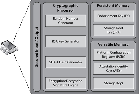
Figure 10-1 Functional components of a trusted platform module
Persistent Memory Two kinds of keys are present in the static memory:
• Endorsement key (EK) A public/private key pair that is installed in the TPM at the time of manufacture and cannot be modified. The private key is always present inside the TPM, while the public key is used to verify the authenticity of the TPM itself. The EK, installed in the TPM, is unique to that TPM and its platform.
• Storage root key (SRK) The master wrapping key used to secure the keys stored in the TPM.
Versatile Memory Three kinds of keys (or values) are present in the versatile memory:
• Platform Configuration Registers (PCRs) Used to store cryptographic hashes of data used for TPM’s sealing functionality.
• Attestation Identity Keys (AIKs) Used for the attestation of the TPM chip itself to service providers. The AIK is linked to the TPM’s identity at the time of development, which in turn is linked to the TPM’s EK. Therefore, the AIK ensures the integrity of the EK.
• Storage keys Used to encrypt the storage media of the computer system.
Hardware Security Module
Whereas a TPM is a microchip installed on a motherboard, a hardware security module (HSM) is a removable expansion card or external device that can generate, store, and manage cryptographic keys. HSMs are commonly used to improve encryption/decryption performance by offloading these functions to a specialized module, thus freeing up the general-purpose microprocessor to take care of, well, general-purpose tasks. HSMs have become critical components for data confidentiality and integrity in digital business transactions. The US Federal Information Processing Standard (FIPS) 140-2 is perhaps the most widely recognized standard for evaluating the security of an HSM. This evaluation is important, because so much digital commerce nowadays relies on protections provided by HSM.
As with so many other cybersecurity technologies, the line between TPMs and HSMs gets blurred. TPMs are typically soldered onto a motherboard, but they can be added through a header. HSMs are almost always external devices, but you will occasionally see them as peripheral component interconnect (PCI) cards. In general, however, TPMs are permanently mounted and used for hardware-based assurance and key storage, while HSMs are removable (or altogether external) and are used for both hardware-accelerated cryptography and key storage.
eFuse
An eFuse is a single bit of nonvolatile memory that, once set to 1, can never be reverted to 0. The technology was invented by IBM in 2004 and is a form of one-time programmable (OTP) memory. It relies on a special compound that normally conducts electricity just fine, but if you apply a specific amount of power, its chemical composition changes and it becomes a resistor instead. Figure 10-2 illustrates these two states. Obviously, this requires special circuits that are able to apply that higher power safely only to the eFuse and then only when instructed to do so. Once an eFuse is programmed or blown, it cannot be reverted to its unprogrammed state.

Figure 10-2 Unprogrammed (left) and programmed (right) eFuses (source: IBM)
eFuses have two main security applications. The first is to disable access to certain functionality on a chip. It is very common for integrated circuits to have all sorts of test and development features during manufacturing that are not needed after the product is shipped. For example, you may want special circuitry that enables an engineer to bypass security controls to test specific features of a chip directly. This is great in the factory but problematic if an attacker is trying to hack a device. Putting an eFuse in front of these test circuits would offer an added layer of protection for the finished hardware.
Another security application of eFuses is to store data. For example, you could use them to keep track of the latest version of firmware you have loaded on a device. This would ensure that nobody could revert the firmware to an earlier (presumably less secure) version. If you have enough eFuses in the chip, you could store cryptographic keys on it, which could be used to verify the integrity of a firmware update by checking its digital signature before installing it. You could also use this approach to verify the integrity of an operating system before you load, which is what secure bootloaders do.
Firmware
Nothing of any significance happens on a computer unless it is done in a processor, and nothing happens in a processor unless it has a sequence of instructions to execute. So the question is, how do you get this jumpstarted when you power on a computer? The processor is typically hardwired to read a specific memory address when it is powered on. This memory address, which is typically a bunch of 0’s, points to the start of section of nonvolatile memory containing instructions and data—in other words, the firmware. It’s called firmware because it sits between the immutable hardware and the ever-changing software, so, in a sense, it is firm. Firmware is the set of instructions and data that take the device from a cold start to the point where it is doing its job (for very simple devices without an operating system) or executing the first instruction in its operating system code.
For many years after personal computers (PCs) emerged, the dominant approach to implementing firmware was the Basic Input/Output System (BIOS) developed by IBM in the 1980s. The very first PCs stored the BIOS firmware in read-only memory (ROM), which could not be overwritten or updated. Any data that needed updating (such as the BIOS password, the location, and types of disk drives) was stored in a battery-powered (but otherwise volatile) complementary metal-oxide-semiconductor (CMOS) RAM chip. If the battery died or was removed, all BIOS settings would revert to default values. The advent of electronically erasable programmable ROM (EEPROM) chips enabled the BIOS to be updated, but it did nothing to negate the need for battery-powered CMOS RAM. This changed when NVRAM became inexpensive and common and opened up a world of possibilities.
By this time, it started to become increasingly clear that BIOS had a large number of problematic features. For starters, it required booting from a local disk drive, which is problematic when you’re trying to manage thousands of workstations in an enterprise environment. It is also built on a 16-bit architecture, which limits its memory address space to 1MB. Finally, it was only a de facto standard that was never really formalized. Even though BIOS is small, simple, and still in common use for embedded devices, something else was needed to power the newer generation of computers.
Unified Extensible Firmware Interface
The Unified Extensible Firmware Interface (UEFI) is a software interface standard that describes the way in which firmware executes its tasks. It is significantly more powerful and flexible than BIOS and has shipped in virtually every workstation and server built in the last ten years. UEFI solved all the problems that BIOS had and introduced some important new features. It enables the use of disk partitions larger than 2TB, and can be booted from disks, removable drives, the local network, and even the Internet using HTTP. Even before loading an OS, UEFI includes networking capabilities that allow for remote recovery and management. It is also modular and works on pretty much any CPU architecture.
The boot process, which has some important security implications, is summarized here:
1. Security Phase (SEC) Initializes a memory cache, establishes a software root of trust, and loads and executes any architecture-specific code needed
2. Pre-EFI Initialization (PEI) Loads and executes code to initialize (and potentially recover) key hardware such as main memory
3. Driver Execution Environment (DXE) Loads and executes the drivers that initialize the rest of the hardware
4. Boot Device Select (BDS) Initializes input and output devices and identifies and loads the boot options
5. Transient System Load (TSL) Invokes the UEFI user interface if available, or the system proceeds to boot the default operating system
6. Runtime (RT) Hands control to the OS loader
As you can see, most of what UEFI does is to figure out what code is needed, load it into memory, and execute it. By default, it trusts all the code that it uses, but there is an option to do better. Secure boot is a feature in UEFI that establishes the root of trust in the firmware. Here’s how it works: UEFI firmware has a root certificate authority (CA) and a set of X.509 certificates belonging to trusted software vendors. Before running an executable (such as a loader or driver), the firmware checks the code’s digital signature to ensure that it is trusted and has not been altered, and then it runs the executable if it checks out. UEFI also has a mechanism for blacklisting certificates and hashes and for updating all this data in a secure manner, as needed.
Measured Boot and Attestation
There may be situations when secure boot is not ideal. Keep in mind that you can only load and run code that is signed by the vendors whose certificates are in the firmware, which means no code developed in-house (unless you also modify the firmware) can be used. For certain mission-critical systems, it may be better to run code that is not verified than to keep the device from booting at all. Additionally, secure boot has no way of verifying configuration settings that are set locally and not at the factory.
Measured boot also starts with a firmware root of trust, but instead of verifying the digital signatures of code, it simply hashes them (a sort of “measurement”) and stores the hash in a secure location. This creates an audit trail of code and data that was loaded. While this certainly has forensic value, it really doesn’t help you detect problems or attacks in real time. Attestation is the process of securely sending the hashes to a management station. It thus makes sense to combine the two and use measured boot and attestation in situations where secure boot is impractical.
Of course, this raises the issue of how to securely compute, store, and transmit the hashes needed for secure boot and attestation. This challenge is typically addressed through the use of a TPM that is separate from the firmware. Whereas TPM is optional in secure boot (since the firmware can do the required tasks), it is almost always necessary for measured boot and attestation.
Trusted Firmware Updates
So far we’ve covered how secure and measured boots are supported by the firmware, but what happens when the firmware needs to be updated? One approach would be simply to overwrite the old firmware with the new one and hope it all works. Even if you independently verify the signatures before updating, you still run the chance that something goes wrong with either the firmware or the hardware and you end up with an unbootable device. A better approach may be to build the downloading, verification, and swapping functions right into the firmware and ensure that it has enough storage space for both versions as well as a small module that would swap from the old to the new when everything checks out. You can think of trusted firmware updates as an extension of secure boot in that the existing firmware is responsible for the security of the entire process.
Firstly, a trusted firmware update system needs enough storage for both the old and the new versions of the firmware simultaneously so you can restore to a known-good version if the download fails. It also needs a small bit of code (a bootloader) to tell the device which version to load up. Finally, and importantly, the system needs a cryptologic module with certificates and code to verify signatures. This last bit could exist in either the bootloader, the firmware images, or externally in a TPM.
Self-Encrypting Drive
Full-disk encryption (FDE) refers to approaches used to encrypt the entirety of data at rest on a disk drive. This can be accomplished in either software or hardware. A self-encrypting drive (SED) is a hardware-based approach to FDE in which a cryptographic module is integrated with the storage media into one package. Typically, this module is built right into the disk controller chip. Most SDEs are built in accordance with the TCG Opal 2.0 standard specification.

NOTE Although SEDs can use onboard TPMs, that is not the norm.
The data stored in an SED is encrypted using symmetric key encryption, and it’s decrypted dynamically whenever the device is read. A write operation works the other way—that is, the plaintext data arrives at the drive and is encrypted automatically before being stored on disk. Because the SED has its own hardware-based encryption engine, it tends to be faster than software-based approaches.
Encryption typically uses the Advanced Encryption Standard (AES) and a 128- or 256-bit key. This data encryption key (DEK) is stored in nonvolatile memory within the cryptographic module and is itself encrypted with a password chosen by the user. Figure 10-3 shows that, if the user changes the password, the same DEK is encrypted with the new password, which means the whole disk doesn’t have to be decrypted and then re-encrypted. If ever there is a need to securely wipe the contents of the SED, the cryptographic module is simply told to generate a new DEK. Since the drive contents were encrypted with the previous (now overwritten) key, that data is effectively wiped. As you can imagine, wiping an SED is almost instantaneous.

Figure 10-3 Changing the password on an SED
Bus Encryption
While the self-encrypting drive protects the data as it rests on the drive, it decrypts the data prior to transferring it to memory for use. This means that an attacker has three opportunities to access the plaintext data: on the external bus connecting the drive to the motherboard (which is sometimes an external cable), in memory, or on the bus between memory and the CPU. What if we moved the cryptographic module from the disk controller to the CPU? This would make it impossible for attackers to access the plaintext data outside the CPU itself, making their job that much harder.
Bus encryption means data and instructions are encrypted prior to being put on the internal bus, which means they are also encrypted everywhere else except when data is being processed. This approach requires a specialized chip, a cryptoprocessor, that combines traditional CPU features with a cryptographic module and specially protected memory for keys. If that sounds a lot like a TPM, it’s because it usually is.
You won’t see bus encryption in general-purpose computers, mostly because the cryptoprocessors are both more expensive and less capable (performance-wise) than regular CPUs. However, bus encryption is a common approach to protecting highly sensitive systems such as automated teller machines (ATMs), satellite television boxes, and military weapon systems. Bus encryption is also widely used for smart cards. All these examples are specialized systems that don’t require a lot of processing power but do require a lot of protection from any attacker who gets his or her hands on them.
Secure Processing
By way of review, data can exist in one of three states: at rest, in motion, or in use. While we’ve seen how encryption can help us protect data in the first two states, it becomes a bit trickier when it is in use. The reason is that processors almost always need unencrypted code and data to work on.
There are three common ways to protect data while it’s in use. The first is to create a specially protected part of the computer in which only trusted applications can run with little or no interaction with each other or those outside the trusted environment. Another approach is to build extensions into the processors that enable it to create miniature protected environments for each application (instead of putting them all together in one trusted environment). Finally, we can just write applications that temporarily lock the processor and/or other resources to ensure nobody interferes with them until they’re done with a specific task. Let’s take a look at these approaches in order.
Trusted Execution Environment
A trusted execution environment (TEE) is a software environment in which special applications and resources (such as files) have undergone rigorous checks to ensure that they are trustworthy and remain protected. Some TEEs, particularly those used in Apple products, are called secure enclaves, but the two terms are otherwise interchangeable. TEEs exist in parallel with untrusted rich execution environments (REEs) on the same platform, as shown in Figure 10-4. They are widely used in mobile devices and increasingly included in embedded and IoT ones as well, to ensure that certain critical applications and their data have guaranteed confidentiality, integrity, and availability. We’re also starting to see them show up in other places, such as microservices and cloud services, where hardware resources are widely shared.

Figure 10-4 A typical TEE and its related REE
A TEE works by creating a trust boundary around itself and strictly controlling the way in which the untrusted REE interacts with the trusted applications. The TEE typically has its own hardware resources (such as a processor core, memory, or persistent storage) that are unavailable to the REE. It also runs its own trusted OS that is separate from and independent of the one in the REE. The two environments interact through a restricted external application programming interface (API) that enables the rich OS to call a limited set of services provided by the REE.
NOTE The term “secure enclave” is most commonly associated with Apple products such as the iPhone, but it is otherwise equivalent to the term “trusted execution environment.”
So, how do TPM, HSM, and TEE differ from each other? A TPM is usually an SoC soldered onto the motherboard to provide limited cryptographic functions. An HSM is a big TPM that plugs into a computer system to provide these functions at a much larger scale. A TEE can perform the functions of a TPM, but, unlike both the TPM and HSM, it is specifically designed to run trusted applications that may have nothing to do with cryptography.
Trusted execution starts with a secure boot, in which the firmware verifies the integrity of the trusted OS bootloader before executing it. In fact, every executable and driver in the TEE is verified to the hardware root of trust and restricted to its own assigned resources. Only specific applications that have undergone rigorous security assessments at the hands of trusted parties are deployed in the TEE by the device manufacturer. This enables trusted applications such as cryptography, identity, and payment systems to enjoy high levels of protection that would otherwise be impossible to attain.

EXAM TIP TEEs (and, by extension, secure enclaves) do not implement hardware roots of trust because they are implemented in software. However, TEEs typically rely on an underlying root of trust provided by a TPM on the device.
Processor Security Extensions
TEEs need hardware support, which all the major chip manufacturers provide in their chipsets. Security is baked into the chips of most modern microprocessors. These CPU packages become a security perimeter outside of which all data and code can exist in encrypted form. Before it can cross into the secure perimeter, everything can be decrypted and/or checked for integrity. Even once allowed inside, data and code are restricted by special controls that ensure what may be done with or to them. For all this to work, however, we need to enable the features through special instructions.
Processor security extensions are instructions that provide these security features in the CPU and can be used to support a TEE. They can, for example, enable programmers to designate special regions in memory as being encrypted and private for a given process. These regions are dynamically decrypted by the CPU while in use, which means any unauthorized process, including the OS or a hypervisor, is unable to access the plaintext stored in them. This feature is one of the building blocks of TEEs, which enables trusted applications to have their own protected memory.
Atomic Execution
Atomic execution is an approach to controlling the manner in which certain sections of a program run so that they cannot be interrupted between the start and end of the section. This prevents other processes from interfering with resources being used by the protected process. To enable this, the programmer designates a section of code as atomic by placing a lock around it. The compiler then leverages OS libraries that, in turn, invoke hardware protections during execution of that locked code segment. The catch is that if you do this too often, you would see some dramatic performance degradation in a modern multithreaded OS. You want to use atomic execution as little as possible to protect critical resources and tasks.
Atomic execution protects against a class of attacks called time-of-check to time-of-use (TOCTOU). This type of attack exploits the dependency on the timing of events that take place in a multitasking OS. When running a program, an OS must carry out instruction 1, then instruction 2, then instruction 3, and so on. This is how it is written. If an attacker can get in between instructions 2 and 3 and manipulate something, she can control the result of these activities. Suppose instruction 1 verifies that a user is authorized to read an unimportant file that is passed as a link, say a help file. Instruction 2 then opens the file pointed to by the link, and instruction 3 closes it after it’s been read by the user. If an attacker can interrupt this flow of execution after instruction 1, change the link to point to a sensitive document, and then allow instruction 2 to execute, the attacker will be able to read the sensitive file even though she isn’t authorized to do so. By enforcing atomic execution of instructions 1 and 2 together, we would protect against TOCTOU attacks.
NOTE This type of attack is also referred to as an asynchronous attack. Asynchronous describes a process in which the timing of each step may vary. The attacker gets in between these steps and modifies something.
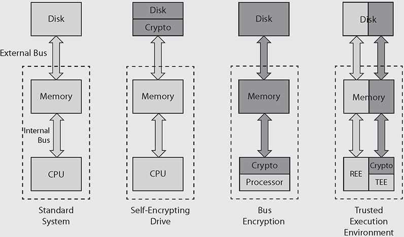
Putting It All Together: Where Can Data Be Encrypted?
Data in a computer system can exist in three different places: in the processor, in memory, and in secondary storage such as a disk drive. Standard systems do not encrypt data in any of these three places by default. You can opt for using FED, such as a self-encrypting drive, to encrypt the data in secondary storage, but that leaves it exposed everywhere else in the system, including the external bus. The third option is to use bus encryption, which requires a cryptoprocessor that is (relatively) expensive and underpowered. You are unlikely to want this unless you really have to protect the data in situations where you assume the adversary will be able to hack your hardware. Finally, the most flexible (and common) balance of protection, per-formance, and cost is the use of TEEs that coexist with untrusted applications. Only the data within the TEE receives the full encryption treatment outside the CPU, leaving everything else to run on regular processor cores.
Trusted Foundry
In their novel Ghost Fleet, authors P.W. Singer and August Cole describe a string of battles that go terribly wrong for the United States. The cause, unbeknownst to the hapless Americans, is a sophisticated program that inserts undetectable backdoors into the computer chips that run everything from missiles to ships. Although the account is fictional, there have been multiple reports in the open media about counterfeit products introducing vulnerabilities into networks, including some in the military.
The threat is real. In 2004, the U.S. Department of Defense (DoD) instituted the Trusted Foundry Program. The goal is to ensure that mission-critical military and government systems can be developed and fielded using a supply chain that is hardened against external threats. A trusted foundry is an organization capable of developing prototype or production-grade microelectronics in a manner that ensures the integrity of their products. The trust is ensured by the National Security Agency through a special review process. At the time of this writing, 77 vendors were rated as trusted foundries and available to DoD customers.
Anti-Tamper Techniques
An important requirement in secure processing is that the hardware resources on which the processor relies is resistant to tampering. Anti-tamper techniques are developed to increase the cost (in terms of hours, money, and/or effort) for an attacker to gain access to or modify the programs and data stored on a hardware device. Determined attackers with virtually unlimited resources (such as some nation states) will eventually be able to compromise any device they can physically get a hold of. Still, we want to make doing so not worth their while.
A common class of physical attacks against integrated circuit chips, microprobing comes in at least two flavors: electronic and visual. In electronic microprobing, the attacker applies voltages to various conductors on the chip and observes the results. Once enough experiments have been conducted, it may be possible for the attacker to map the functions of the chip and extract useful information. One of the risks with this approach is that if an attacker applies the wrong amount of electricity in the right place, he could burn out a part of the chip and make the job a lot harder.
In a visual attack, the attacker carefully removes very thin slices of the chip, exposing its layers of individual components. This can be done with an abrasive rotary tool, with a laser cutter, or with chemicals. Using a microscope, it is possible to map out the circuitry and even read individual bits of memory. Obviously, this is a destructive process, but it can reveal a great deal of information given enough time.
There are a number of anti-tamper techniques to defeat microprobing and other physical attacks. Electronic microprobing can be thwarted through the generation of random signals. Integrated circuits normally have predictable clock signals and execute an instruction (or enable a state change) deterministically at particular points in time. But what if the chip were designed to use a random timing signal that only the manufacturer knew? Alternatively, what if each legitimate instruction were sandwiched between a random number of bogus ones? The result would be a chip that would be nearly impossible to understand, let alone manipulate by an adversary.
The attacker may decide to open the chip physically and visually examine its inner workings. One way to defeat this attack is to build a microscopic mesh between the chip and its plastic casing, and then monitor it for breaches. If the plastic casing is removed, whether chemically or mechanically, it is extremely likely to break one of the tiny conductors on the mesh. This event can trigger automatic zeroization of nonvolatile memory and perhaps even the firmware. These countermeasures, called active meshes, are commonly used in smart cards and in mobile subscriber identification modules (SIMs).
Chapter Review
Hardware roots of trust are essential to building secure systems, because without them, attackers can easily access and even modify data and code. Fortunately, most modern CPUs ship with a wealth of hardware features that can be used to provide this security. The catch is that many systems do not take full advantage of these features. It is a good idea to explore how your operating systems and applications leverage trusted platform modules and processor security extensions. If you’re not taking advantage of these capabilities, it would be a good idea to look for opportunities to integrate them into your security architecture.
Questions
1. Which of the following implements a hardware root of trust?
A. Trusted Platform Module (TPM)
B. eFuse
C. Unified Extensible Firmware Interface (UEFI)
D. Trusted foundry
2. Which of the following is not a good use of eFuses?
A. Keeping track of firmware updates
B. Storing session keys
C. Disabling test functions on a chip
D. Storing digital certificates
3. Where is the data encrypted in a self-encrypting drive system?
A. On the disk drive
B. In memory
C. On the bus
D. All of the above
4. Where is the data encrypted in a bus encryption system?
A. On the disk drive
B. In memory
C. On the bus
D. All the above
5. What is the difference between a Trusted Platform Module (TPM) and a Hardware Security Module (HSM)?
A. HSM is typically on the motherboard and TPM is an external device.
B. Only an HSM can store multiple digital certificates.
C. There is no difference, as both terms refer to the same type of devices.
D. TPM is typically on the motherboard and HSM is an external device.
6. Which of the following is not a required feature in a TPM?
A. Hashing
B. Certificate revocation
C. Certificate storage
D. Encryption
7. Which of the following is true about changing the password on a self-encrypting drive?
A. It requires re-encryption of stored data.
B. The new password is encrypted with the existing data encryption key.
C. It has no effect on the encrypted data.
D. It causes a new data encryption key to be generated.
8. Which of these is true about processor security extensions?
A. They are after-market additions by third parties.
B. They must be disabled in order to establish trusted execution environments.
C. They enable developers to encrypt memory associated with a process.
D. Encryption is not normally one of their features.
Answers
1. A. Trusted Platform Modules (TPMs) and Hardware Security Modules (HSMs) are the two best examples of devices that implement a hardware root of trust.
2. B. Session keys are single-use symmetric keys used for one specific session, which means that they change all the time. Because eFuses are programmable only once, this use would quickly exhaust them.
3. A. Self-encrypting drives include a hardware module that decrypts the data prior to putting it on the external bus, so the data is protected only on the drive itself.
4. D. In systems that incorporate bus encryption, the data is decrypted only on the cryptoprocessor. This means that the data is encrypted everywhere else on the system.
5. D. In general, TPMs are permanently mounted on the motherboard and used for hardware-based assurance and key storage, while HSMs are removable or altogether external and are used for both hardware accelerated cryptography and key storage.
6. B. Certificate revocation is not a required feature in a TPM. TPMs must provide storage of cryptographic keys and digital certificates, symmetric and asymmetric encryption, and hashing.
7. C. When you change the password on a self-encrypting drive, the existing DEK is retained but is encrypted with the new password. This means the encrypted data on the disk remains unaltered.
8. C. Processor security extensions are instructions that provide security features in the CPU and can be used to support a TEE. They can, for example, enable programmers to designate special regions in memory as being encrypted and private for a given process.