A VHDL Primer
The Essentials
Abstract
This chapter is designed to give concise and useful summary information on important language constructs and usage in VHDL, hopefully helpful and easy to use, but not necessarily comprehensive. The information is intended for the reader to understand the key concepts in this book. This chapter will introduce the key concepts in VHDL and the important syntax required for most VHDL designs, particularly with reference to FPGAs.
3.1 Introduction
This chapter of the book is not intended as a comprehensive VHDL reference book as there are many excellent texts available that fit that purpose, including Zwolinski [1], Navabi [2], or Ashenden [3] (full details are provided in the References heading).
Instead, this chapter is designed to give concise and useful summary information on important language constructs and usage in VHDL, hopefully helpful and easy to use, but not necessarily comprehensive. The information is helpful enough for the reader to understand the key concepts in this book; however, I would thoroughly recommend obtaining access to a textbook on VHDL or Verilog if the reader is serious in becoming expert in HDL design for digital systems. This book is intended as a complement to a textbook.
This chapter will introduce the key concepts in VHDL and the important syntax required for most VHDL designs, particularly with reference to FPGAs. In most cases, the decision to use VHDL over other languages such as Verilog or SystemC will have less to do with designer choice and more to do with software availability and company decisions. Over the last decade or so, a war of words has raged between the VHDL and Verilog communities about which is the best language, and in most cases it is completely pointless as the issue is more about design than syntax. There are numerous differences in the details between VHDL and Verilog, but the fundamental philosophical difference historically has been the design context of the two languages.
Verilog has come from a bottom-up tradition and has been heavily used by the IC industry for cell-based design, whereas the VHDL language has been developed much more from a top-down perspective. Of course, these are generalizations and largely out of date in a modern context, but the result is clearly seen in the basic syntax and methods of the two languages. While this has possibly been the case in the past, with the advent of the higher level “SystemVerilog” variant of Verilog providing much of the same capability as VHDL at the system level, this has also become popular.
Unfortunately, while there are many languages now available to designers, most of the FPGA design tools support subsets, and therefore in some cases support for SystemVerilog may be patchy. It is therefore useful to describe using VHDL and Verilog; however, this book will also provide some introductory material to SystemVerilog for completeness.
Without descending into a minute dissection of the differences between Verilog and VHDL, one important aspect of VHDL is the ability to use multiple levels of model with different architectures as shown in Figure 3.1.
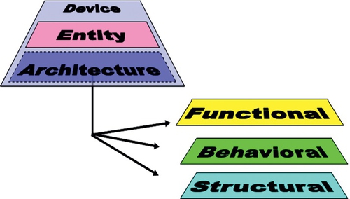
This is not unique to VHDL, and in fact Verilog does have the concept of different behavior in a single module; however, it is explicitly defined in VHDL and is extremely useful in putting together practical multi-level designs in VHDL. The division of a model into its interface part (the entity in VHDL) and the behavior part (the architecture in VHDL) is an incredibly practical approach for modeling multiple behavior for a single interface and makes model exchange and multiple implementation practical.
The remainder of this chapter will describe the key parts of VHDL, starting with the definition of a basic model structure using entities and architectures, discuss the important variable types, review the methods of encapsulating concurrent, sequential and hierarchical behavior and finally introduce the important fundamental data types required in VHDL.
3.2 Entity: Model Interface
3.2.1 The Entity Definition
The VHDL entity defines how a design element described in VHDL connects to other VHDL models and also defines the name of the model. The entity also allows the definition of any parameters that are to be passed into the model using hierarchy. The basic template for an entity is as follows:
If the entity has the name test then the entity template could be either:
or:
3.2.2 Ports
The method of connecting entities together is using ports. These are defined in the entity using the following method:
The port declaration defines the type of connection and direction where appropriate. For example, the port declaration for an input bit called in1 would be:
And if the model had two inputs (in1 and in2) of type bit and a single output (out1) of type bit then the declaration of the ports would be defined as follows:
As the connection points between entities are effectively the same as those inter-process connections, they are effectively signals and can be used as such within the VHDL of the model.
3.2.3 Generics
If the model has a parameter, then this is defined using generics. The general declaration of generics is shown below:
In the case of generics, the declaration is similar to that of a constant with the form as shown below:
Taking an example of a model that had two generics, gain (integer) and time_delay (time), they could be defined in the entity as follows:
3.2.4 Constants
It is also possible to include model specific constants in the entity using the standard declaration of constants method previously described; for example:
3.2.5 Entity Examples
To illustrate a complete entity, we can bring together the ports and generics examples previously shown and construct the complete entity for this example:
3.3 Architecture: Model Behavior
3.3.1 Basic Definition of An Architecture
While the entity describes the interface and parameter aspects of the model, the architecture defines the behavior. There are several types of VHDL architecture and VHDL allows different architectures to be defined for the same entity. This is ideal for developing behavioral, RTL, and gate level architectures that can be incorporated into designs and tested using the same test benches.
The basic approach for declaring an architecture could be as follows:
or
3.3.2 Architecture Declaration Section
After the declaration of the architecture name and before the begin statement, any local signals or variables can be declared. For example, if there were two internal signals to the architecture called sig1 and sig2, they could be declared in the declaration section of the model as follows:
Then the signals can be used in the architecture statement section.
3.3.3 Architecture Statement Section
VHDL architectures can have a variety of structures to achieve different types of functionality. Simple combinatorial expressions use signal assignments to set new signal values as shown below:
Note that for practical design, the use of the after 10 ns statement is not synthesizable. In practice, the only way to ensure correct synthesizable design is to either make the design delay insensitive or synchronous. The design of combinatorial VHDL will result in additional delays due to the technology library gate delays, potentially resulting in glitches or hazards. An example of a multiple gate combinatorial architecture, using internal signal declarations is given below:
3.4 Process: Basic Functional Unit in VHDL
The process in VHDL is the mechanism by which sequential statements can be executed in the correct sequence, and with more than one process, concurrently. Each process consists of a sensitivity list, declarations, and statements. The basic process syntax is given below:
The sensitivity list allows a process to be activated when a specific signal changes value; for example a typical usage would be to have a global clock and reset signal to control the activity of the process, as follows:
In this example, the process would only be activated when either clk or rst changed value. Another way of encapsulating the same behavior is to use a wait statement in the process so that the process is automatically activated once, and then waits for activity on either signal before running the process again. The same process could then be written as follows:
In fact, the location of the wait statement is not important, as the VHDL simulation cycle executes each process once during initialization, and so the wait statement could be at the start or the end of the process and the behavior would be the same in both cases.
In the declaration section of the process, signals and variables can be defined locally as described previously; for example, a typical process may look like the following:
The local signal na and the process are activated by changes on the signal a which is externally declared (with respect to the process).
3.5 Basic Variable Types and Operators
3.5.1 Constants
When a value needs to be static throughout a simulation, the type of element to use is a constant. This is often used to initialize parameters or to set fixed register values for comparison. A constant can be declared for any defined type in VHDL with examples as follows:
3.5.2 Signals
Signals are the link between processes and sequential elements within processes. They are effectively wires in the design and connect all the design elements together. When simulating signals, the simulator will in turn look at updating the signal values and also checking the sensitivity lists in processes to see whether any changes have occurred that will mean that processes become active.
Signals can be assigned immediately or with a time delay, so that an event is scheduled for sometime in the future (after the specified delay). It is also important to recognize that signals are not the same as a set of sequential program code (such as in C), but are effectively concurrent signals that will not be able to be considered stable until the next time the process is activated.
Examples of signal declaration and assignment are shown below:
3.5.3 Variables
While signals are the external connections between processes, variables are the internal values within a process. They are only used in a sequential manner, unlike the concurrent nature of signals within and between processes. Variables are used within processes and are declared and used as follows:
Notice that there is no concept of a delay in the variable assignment; if you need to schedule an event, it is necessary to use a signal.
3.5.4 Boolean Operators
VHDL has a set of standard Boolean operators built in, which are self explanatory. The list of operators are and, or, nand, not, nor, xor. These operators can be applied to BIT, BOOLEAN, or logic types with examples as follows:
3.5.5 Arithmetic Operators
There are a set of arithmetic operators built into VHDL which again are self explanatory and these are described and examples provided as follows:
3.5.6 Comparison Operators
VHDL has a set of standard comparison operators built in, which are self explanatory. The operators are =, / =, <, <=, >, >=. These operators can be applied to a variety of types as follows:
3.5.7 Logical Shifting Functions
VHDL has a set of six built-in logical shift functions which are summarized in the following table:
3.5.8 Concatenation
The concatenation function in VHDL is denoted by the & symbol and is used as follows:
3.6 Decisions and Loops
3.6.1 If-Then-Else
The basic syntax for a simple if statement is as follows:
The condition is a Boolean expression, of the form a > b or a = b. Note that the comparison operator for equality is a single =, not to be confused with the double == used in some programming languages. For example, if two signals are equal, then setting an output high would be written in VHDL as:
If the decision needs to have both the if and else options, then the statement is extended as follows:
So in the previous example, we could add the else statements as follows:
And finally, multiple if conditions can be implemented using the general form:
With an example:
3.6.2 Case
As we have seen with the if statement, it is relatively simple to define multiple conditions, but it becomes a little cumbersome, and so the case statement offers a simple approach to branching, without having to use Boolean conditions in every case. This is especially useful for defining state diagrams or for specific transitions between states using enumerated types. An example of a case statement is:
This can be extended to a range of values, not just a single value:
It is also possible to use Boolean conditions and equations. In the case of the default option (i.e., when none of the conditions have been met), then the term “when others” can be used:
3.6.3 For
The most basic loop in VHDL is the for loop. This is a loop that executes a fixed number of times. The basic syntax for the for loop is shown below:
It is also possible to execute a loop that counts down rather than up, and the general form of this loop is:
A typical example of a for loop would be to pack an array with values bit by bit, for example:
3.6.4 While and Loop
Both the while and loop loops have an indeterminant number of loops, compared to the fixed number of loops in a for loop and as such are usually not able to be synthesized. For FPGA design, they are not feasible as they will usually cause an error when the VHDL model is compiled by the synthesis software.
3.6.5 Exit
The exit command allows a for loop to be exited completely. This can be useful when a condition is reached and the remainder of the loop is no longer required. The syntax for the exit command is shown below:
3.6.6 Next
The next command allows a for loop iteration to be exited; this is slightly different from the exit command in that the current iteration is exited, but the overall loop continues onto the next iteration. This can be useful when a condition is reached and the remainder of the iteration is no longer required. An example for the next command is shown below:
3.7 Hierarchical Design
3.7.1 Functions
Functions are a simple way of encapsulating behavior in a model that can be reused in multiple architectures. Functions can be defined locally to an architecture or more commonly in a package (discussed in Part 2 of this book), but in this section the basic approach of defining functions will be described. The simple form of a function is to define a header with the input and output variables as shown here:
For example, a simple function that takes two input numbers and multiplies them together could be defined as follows:
3.7.2 Packages
Packages are a common single way of disseminating type and function information in the VHDL design community. The basic definition of a package is as follows:
As can be seen, the package consists of two parts, the header and the body. The header is the place where the types and functions are declared, and the package body is where the declarations themselves take place.
For example, a function could be described in the package body and the function is declared in the package header. Take a simple example of a function used to carry out a simple logic function:
The VHDL function would be something like the following:
The resulting package declaration would then use the function in the body and the function header in the package header thus:
3.7.3 Components
While procedures, functions, and packages are useful in including behavioral constructs generally, with VHDL being used in a hardware design context, often there is a need to encapsulate design blocks as a separate component that can be included in a design, usually higher in the system hierarchy.
The method for doing this in VHDL is called a component. Caution needs to be exercised with components as the method of including components changed radically between VHDL 1987 and VHDL 1993, as such care needs to be taken to ensure that the correct language definitions are used consistently.
Components are a way of incorporating an existing VHDL entity and architecture into a new design without including the previously created model. The first step is to declare the component in a similar way that functions need to be declared. For example, if an entity is called and4, and it has four inputs (a,b,c,d of type bit) and one output (q of type bit), then the component declaration would be of the form shown here:
Then this component can be instantiated in a netlist form in the VHDL model architecture:
Note that in this case, there is no explicit mapping between port names and the signals in the current level of VHDL; the pins are mapped in the same order as defined in the component declaration. If each pin is to be defined independently of the order of the pins, then the explicit port map definition needs to be used:
The final thing to note is that this is called the default binding. The binding is the link between the compiled architecture in the current library and the component being used. It is possible, for example, to use different architectures for different instantiated components using the following statement for a single specific device:
or the following to specify a specific device for all the instantiated components:
3.7.4 Procedures
Procedures are similar to functions, except that they have more flexibility in the parameters, in that the direction can be in, out or inout. This is useful in comparison to functions where there is generally only a single output (although it may be an array) and avoids the need to create a record structure to manage the return value. Although procedures are useful, they should be used only for small specific functions. Components should be used to partition the design, not procedures, and this is especially true in FPGA design, as the injudicious use of procedures can lead to bloated and inefficient implementations, although the VHDL description can be very compact. A simple procedure to execute a full adder could be of the form:
Notice that the syntax is the same as that for variables (not signals), and that multiple outputs are defined without the need for a return statement.
3.8 Debugging Models
3.8.1 Assertions
Assertions are used to check if certain conditions have been met in the model and are extremely useful in debugging models. Some examples:
3.9 Basic Data Types
3.9.1 Basic Types
VHDL has the following standard types defined as built-in data types:
• Boolean
• bit_vector
• integer
• real
3.9.2 Data Type: bit
The bit data type is the simple logic type built into VHDL. The type can have two legal values 0 or 1. The elements defined as of type bit can have the standard VHDL built-in logic functions applied to them. Examples of signal and variable declarations of type bit follow:
3.9.3 Data Type: Boolean
The Boolean data type is primarily used for decision making, so the test value for if statements is a Boolean type. The elements defined as of type Boolean can have the standard VHDL built-in logic functions applied to them. Examples of signal and variable declarations of type Boolean follow:
3.9.4 Data Type: Integer
The basic numeric type in VHDL is the integer and is defined as an integer in the range −2147483647 to +2147483647. There are obviously implications for synthesis in the definition of integers in any VHDL model, particularly the effective number of bits, and so it is quite common to use a specified range of integer to constrain the values of the signals or variables to within physical bounds. Examples of integer usage follow:
There are two subtypes (new types based on the fundamental type) derived from the integer type which are integer in nature, but simply define a different range of values, as described in the following subsections.
3.9.5 Integer Subtypes: Natural
The Natural subtype is used to define all integers greater than and equal to zero. They are actually defined with respect to the high value of the integer range as follows:
3.9.6 Integer Subtypes: Positive
The Positive subtype is used to define all integers greater than and equal to one. They are actually defined with respect to the high value of the integer range as follows:
3.9.7 Data Type: Character
In addition to the numeric types inherent in VHDL, there are also the complete set of ASCII characters available for designers. There is no automatic conversion between characters and a numeric value per se, but there is an implied ordering of the characters defined in the VHDL standard (IEEE Std 1076-1993). The characters can be defined as individual characters or arrays of characters to create strings. The best way to consider characters is as an enumerated type.
3.9.8 Data Type: Real
Floating point numbers are used in VHDL to define real numbers and the predefined floating point type in VHDL is called real. This defines a floating point number in the range −1.0e38 to +10e38. This is an important issue for many FPGA designs, as most commercial synthesis products do not support real numbers precisely because they are floating point. In practice it is necessary to use integer or fixed point numbers which can be directly and simply synthesized into hardware. An example of defining real signals or variables is shown here:
3.9.9 Data Type: Time
Time values are defined using the special time type. These not only include the time value, but also the unit separated by a space. The basic range of the time type value is between −2147483647 to 2147483647 and the basic unit of time is defined as the femtosecond (fs).
Each subsequent time unit is derived from this basic unit of the fs as shown here:
Examples of time definitions are shown here:
3.10 Summary
This chapter provides a very brief introduction to VHDL and is certainly not a comprehensive reference. It enables the reader, hopefully, to have enough knowledge to understand the syntax of the examples in this book. The author strongly recommends that anyone serious about design with VHDL should also obtain a detailed and comprehensive reference book on VHDL, such as Zwolinski [1] (a useful introduction to digital design with VHDL (and a common student textbook)) or Ashenden [3] (a more heavy-duty VHDL reference that is perhaps more comprehensive, but less easy for a beginner to VHDL).