Secure Systems
Abstract
This chapter introduces the key concepts in implementing block ciphers such as the data encryption standard (DES). A stream cipher operates on a digital data stream one or more bits at a time. A block cipher operates on complete blocks of data at any one time and produces a ciphertext block of equal size. DES, in common with other block ciphers is based around a structure called a Feistel Lattice so it is useful to describe how this works.
10.1 Introduction to Block Ciphers
The data encryption standard (DES) is a symmetric block cipher. A stream cipher operates on a digital data stream one or more bits at a time. A block cipher operates on complete blocks of data at any one time and produces a ciphertext block of equal size. DES is a block cipher that operates on data blocks of 64 bits in size. DES uses a 64-bit key 8 × 8 including 1 bit for parity, so the actual key is 56 bits. DES, in common with other block ciphers, is based around a structure called a Feistel Lattice so it is useful to describe how this works.
10.2 Feistel Lattice Structures
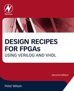
A block cipher operates on a plaintext block of n bits to produce a block of ciphertext of n bits. For the algorithm to be reversible (i.e., for decryption to be possible) there must be a unique mapping between the two sets of blocks. This can also be called a non singular transformation. For example, consider the following transformations as shown in Figure 10.1.
Obviously, this is essentially a substitution cipher, which may be susceptible to the standard statistical analysis techniques used for simple cryptanalysis of text (such as frequency analysis). As the block size increases, then this becomes increasingly less feasible. An obvious practical difficulty with this approach is the number of transformations required as n increases. This mapping is essentially the key and the number of bits will determine the key size. Therefore, for an n-bit general substitution block cipher, the key size is calculated as follows:
For a specific case where n = 64, the key size becomes 64 × 264 = 1021.
In order to get around this complexity problem, Feistel proposed an approach called a product cipher whereby the combination of several simple steps leads to a much more cryptographically secure solution than any of the component ciphers used. His approach relies on the alternation of two types of function:
• Confusion
These two concepts are grounded in an approach developed by Shannon used in most standard block ciphers in common use today. Shannon’s goal was to define cryptographic functions that would not be susceptible to statistical analysis. He therefore proposed two methods for reducing the ability of statistical cryptanalysis to find the original message, classified as diffusion and confusion.
In diffusion, the statistical structure of the plaintext is dissipated throughout the long-term statistics of the ciphertext. This is achieved by making each bit of the plaintext affect the value of many bits of the ciphertext. An example of this would be to add letters to a ciphertext such that the frequency of each letter is the same, regardless of the message. In binary block ciphers the technique uses multiple permutations and functions such that each bit of the ciphertext is affected by multiple bits in the plaintext.
Each block of plaintext is transformed into a block of ciphertext, and this depends on the key. Confusion aims to make the relationship between the ciphertext and the key as complex as possible to reduce the possibility of ascertaining the key. This requires a complex substitution algorithm, as a linear substitution would not protect the key.
Both diffusion and confusion are the cornerstones of successful block cipher design.
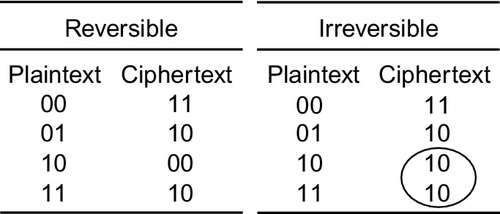
The result of these requirements is the Feistel Lattice (shown in Figure 10.2). This is the basic architecture that is used in block ciphers such as DES.

The inputs to the algorithm are the plaintext (of length 2w bits) and a key K. The plaintext is split into two halves L and R, and the data is then passed through n rounds of processing and then recombined to produce the ciphertext. Each round has an input Li−1 and Ri−1 derived from the previous round and a subkey Ki, derived from the overall key K. Each round has the same structure. The left half of the data has a substitution performed. This requires a round function F to be performed on the right half of the data and then XORed with the left half. Finally a permutation is performed that requires the interchange of the two halves of the data.
The implementation of a Feistel network has the following key parameters:
• Block size A larger block size generally means greater security, but reduced speed. 64-bit block sizes are very heavily used as being a reasonable trade-off—although AES now uses 128 bits.
• Key Size The same trade-off applies as for block size. Generally 64 bits is not now considered adequate and 128 bits is preferred.
• Number of rounds Each round adds additional security. A single round is inadequate, but 16 is considered standard.
• Subkey generation The more complex this algorithm is, the more secure the overall system will be.
• Round function Greater complexity again means greater resistance to cryptanalysis.
10.3 The Data Encryption Standard (DES)
10.3.1 Introduction
The Data Encryption Standard (DES) was adopted by the National Institute of Standards and Technology (NIST) in 1977 as the Federal Information Processing Standards 46 (FIPS PUB 46). As mentioned previously, the algorithm operates on plaintext blocks of 64 bits and the key size is 56 bits. By 1999, NIST had decreed that DES was no longer secure and should only be used for legacy systems and that triple DES should be used instead. As will be described later, DES has since been superceded by the Advanced Encryption Standards (AES). The coarse structure (overall architecture) of DES is shown in Figure 10.3.
The center section (where the main repetition occurs) is called the fine structure and is where the details of the encryption take place. This fine structure is detailed in Figure 10.4.

The fine structure of DES consists of several important functional blocks:
• Initial permutation Fixed, known mapping 64-64 bits.
• Key transformations Circular L shift of keys by A(i) bits in round (A(i) is known and fixed).
• Compression Permutation Fixed known subset of 56-bit input mapped onto 48-bit output.
• Expansion permutation 32-bit data shuffled and mapped (both operations fixed and known) onto 48 bits by duplicating 16 input bits. This makes diffusion quicker.
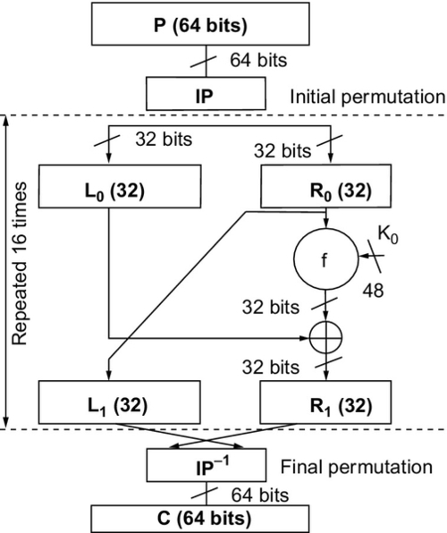
Another significant section of the algorithm is the substitution or S-box. The nonlinear aspect of the cipher is vital in cryptography. In DES the eight S boxes each contain four different (fixed and known) 4:4 input maps. These are selected by the extra bits created in the expansion box. The S boxes are structured as shown in Figure 10.5.
The final part of the DES structure is the key generation architecture for the individual round keys and this is given in Figure 10.6.

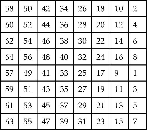
The remaining functional block is the initial and final permutation. The initial permutation (P-Box) is a 32:32 fixed, known bit permutation. The final permutation is the inverse of the initial permutation. The initial permutation is defined using the following table:
10.3.2 DES VHDL Implementation
DES can be implemented in VHDL using a structural or a functional approach. As has been discussed previously, there are advantages to both methods; however, the DES algorithm is tied implicitly to the structure, so a structural approach will give an efficient implementation.
Implementing the initial permutation in VHDL requires a 64-bit input vector and a 64-bit output vector. We can create this in VHDL with an entity that defines an input and output std_logic vector as follows. The architecture is simply the assignment of bits from input to output according to the initial permutation table previously defined.
As this function is purely combinatorial we don’t need to have a register (i.e., clocked input) on this model, although we could implement that if required using a simple process.
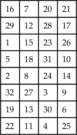
As shown in the previous description of the expansion function, we need to take a word consisting of 32 bits and expand it to 48 bits. This requires a translation table as shown below. Notice that there are duplicates in the cell which means that you only need 32 input bits to obtain 48 output bits.

We can use a VHDL model similar to the initial permutation function, except that in this case there are 32 input bits and 48 output bits. Notice that some of the input bits are repeated, giving a straightforward expansion function.
The architecture is simply the assignment of bits from input to output according to the initial permutation table previously defined.
The final permutation block is the permutation marked (P) on the fine structure after the key function. This is a straightforward bit substitution function with 32 bits input and 32 bits output. The bit translation table is shown in the following table:

This is implemented in VHDL using exactly the same approach as the previous expansion and permutation functions as follows:
The architecture is simply the assignment of bits from input to output according to the initial permutation table previously defined.
The nonlinear part of the DES algorithm is the S box. This is a set of 6->4 bit transformations that reduce the 48 bits of the expanded word in the DES f function to the 32 bits for the next round. The required row and column are obtained from the data passed into the S box. The data into the S box is a 6-bit binary word. The row is obtained from 2.b1 + b6 and the column is obtained from b2b3b4b5. For example, S(011011) would give a row of 01 (1) and a column of 1101 (13). For S8 this would result in a value returning of 1110 (14).
The basic S-box entity can therefore be constructed using the following VHDL:
One approach is to define the row and column from the input D word and then calculate the output Y word from that using a lookup table approach or minimize the logic as a truth table. The basic architecture could then look something like this:
Another approach is to define a simple lookup table with the input d as the unique address and the output y stored in the memory; this is exactly the same as a ROM, so the input is defined as an unsigned integer to look up the required value. In this case the memory is defined in exactly the same way as the ROM separately in this book.
The S-box substitutions are given in the table following and the VHDL can either use the lookup table approach to store the address of each substitution, or logic can be used to decode the correct output.
| Row | Column Number | |||||||||||||||
| [0] | [1] | [2] | [3] | [4] | [5] | [6] | [7] | [8] | [9] | [10] | [11] | [12] | [13] | [14] | [15] | |
| S1 | ||||||||||||||||
| [0] | 14 | 4 | 13 | 1 | 2 | 15 | 11 | 8 | 3 | 10 | 6 | 12 | 5 | 9 | 0 | 7 |
| [1] | 0 | 15 | 7 | 4 | 14 | 2 | 13 | 1 | 10 | 6 | 12 | 11 | 9 | 5 | 3 | 8 |
| [2] | 4 | 1 | 14 | 8 | 13 | 6 | 2 | 11 | 15 | 12 | 9 | 7 | 3 | 10 | 5 | 0 |
| [3] | 15 | 12 | 8 | 2 | 4 | 9 | 1 | 7 | 5 | 11 | 3 | 14 | 10 | 0 | 6 | 13 |
| S2 | ||||||||||||||||
| [0] | 15 | 1 | 8 | 14 | 6 | 11 | 3 | 4 | 9 | 7 | 2 | 13 | 12 | 0 | 5 | 10 |
| [1] | 3 | 13 | 4 | 7 | 15 | 2 | 8 | 14 | 12 | 0 | 1 | 10 | 6 | 9 | 11 | 5 |
| [2] | 0 | 14 | 7 | 11 | 10 | 4 | 13 | 1 | 5 | 8 | 12 | 6 | 9 | 3 | 2 | 15 |
| [3] | 13 | 8 | 10 | 1 | 3 | 15 | 4 | 2 | 11 | 6 | 7 | 12 | 0 | 5 | 14 | 9 |
| S3 | ||||||||||||||||
| [0] | 10 | 0 | 9 | 14 | 6 | 3 | 15 | 5 | 1 | 13 | 12 | 7 | 11 | 4 | 2 | 8 |
| [1] | 13 | 7 | 0 | 9 | 3 | 4 | 6 | 10 | 2 | 8 | 5 | 14 | 12 | 11 | 15 | 1 |
| [2] | 13 | 6 | 4 | 9 | 8 | 15 | 3 | 0 | 11 | 1 | 2 | 12 | 5 | 10 | 14 | 7 |
| [3] | 1 | 10 | 13 | 0 | 6 | 9 | 8 | 7 | 4 | 15 | 14 | 3 | 11 | 5 | 2 | 12 |
| S4 | ||||||||||||||||
| [0] | 7 | 13 | 14 | 3 | 0 | 6 | 9 | 10 | 1 | 2 | 8 | 5 | 11 | 12 | 4 | 15 |
| [1] | 13 | 8 | 11 | 5 | 6 | 15 | 0 | 3 | 4 | 7 | 2 | 12 | 1 | 10 | 14 | 9 |
| [2] | 10 | 6 | 9 | 0 | 12 | 11 | 7 | 13 | 15 | 1 | 3 | 14 | 5 | 2 | 8 | 4 |
| [3] | 3 | 15 | 0 | 6 | 10 | 1 | 13 | 8 | 9 | 4 | 5 | 11 | 12 | 7 | 2 | 14 |
| S5 | ||||||||||||||||
| [0] | 2 | 12 | 4 | 1 | 7 | 10 | 11 | 6 | 8 | 5 | 3 | 15 | 13 | 0 | 14 | 9 |
| [1] | 14 | 11 | 2 | 12 | 4 | 7 | 13 | 1 | 5 | 0 | 15 | 10 | 3 | 9 | 8 | 6 |
| [2] | 4 | 2 | 1 | 11 | 10 | 13 | 7 | 8 | 15 | 9 | 12 | 5 | 6 | 3 | 0 | 14 |
| [3] | 11 | 8 | 12 | 7 | 1 | 14 | 2 | 13 | 6 | 15 | 0 | 9 | 10 | 4 | 5 | 3 |
| S6 | ||||||||||||||||
| [0] | 12 | 1 | 10 | 15 | 9 | 2 | 6 | 8 | 0 | 13 | 3 | 4 | 14 | 7 | 5 | 11 |
| [1] | 10 | 15 | 4 | 2 | 7 | 12 | 9 | 5 | 6 | 1 | 13 | 14 | 0 | 11 | 3 | 8 |
| [2] | 9 | 14 | 15 | 5 | 2 | 8 | 12 | 3 | 7 | 0 | 4 | 10 | 1 | 13 | 11 | 6 |
| [3] | 4 | 3 | 2 | 12 | 9 | 5 | 15 | 10 | 11 | 14 | 1 | 7 | 6 | 0 | 8 | 13 |
| S7 | ||||||||||||||||
| [0] | 4 | 11 | 2 | 14 | 15 | 0 | 8 | 13 | 3 | 12 | 9 | 7 | 5 | 10 | 6 | 1 |
| [1] | 13 | 0 | 11 | 7 | 4 | 9 | 1 | 10 | 14 | 3 | 5 | 12 | 2 | 15 | 8 | 6 |
| [2] | 1 | 4 | 11 | 13 | 12 | 3 | 7 | 14 | 10 | 15 | 6 | 8 | 0 | 5 | 9 | 2 |
| [3] | 6 | 11 | 13 | 8 | 1 | 4 | 10 | 7 | 9 | 5 | 0 | 15 | 14 | 2 | 3 | 12 |
| S8 | ||||||||||||||||
| [0] | 13 | 2 | 8 | 4 | 6 | 15 | 11 | 1 | 10 | 9 | 3 | 14 | 5 | 0 | 12 | 7 |
| [1] | 1 | 15 | 13 | 8 | 10 | 3 | 7 | 4 | 12 | 5 | 6 | 11 | 0 | 14 | 9 | 2 |
| [2] | 7 | 11 | 4 | 1 | 9 | 12 | 14 | 2 | 0 | 6 | 10 | 13 | 15 | 3 | 5 | 8 |
| [3] | 2 | 1 | 14 | 7 | 4 | 10 | 8 | 13 | 15 | 12 | 9 | 0 | 3 | 5 | 6 | 11 |
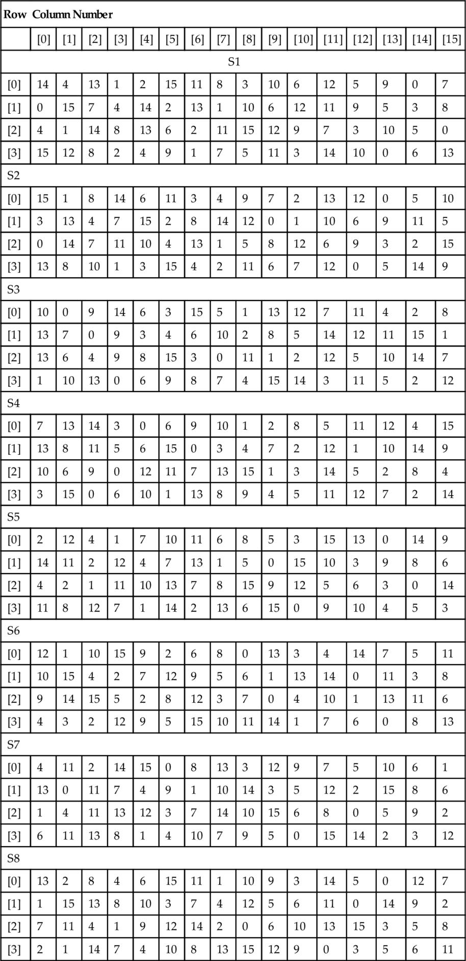
In order to use this table, the appropriate S box is selected and then the 2 bits of the row select the appropriate row and the same for the column. For example, for S box S1, if the row is 3 (11) and the Column is 10 (1010) then the output can be read off as 3 (0011). This can be coded in VHDL using nested case statements as follows:
Obviously this is quite cumbersome, but also very easy to code automatically using a simple code generator and offers the possibility of the synthesis tool carrying out logic optimization and providing a much more efficient implementation than a memory block.
10.3.3 DES Verilog Implementation
DES can also be implemented in Verilog using a structural or a functional approach. As has been discussed previously, there are advantages to both methods; however, the DES algorithm is tied implicitly to the structure, so a structural approach will give an efficient implementation.
Implementing the initial permutation in Verilog requires a 64-bit input vector and a 64-bit output vector. In Verilog this is very easy to create by simply specifying the size of the input and output accordingly. In this combinatorial example (the same as the VHDL example previously in this chapter), we have not used an enable signal, but this would be easy to add, and then of course we can implement the output with a high impedance (z) state for unknown input values.
As this function is purely combinatorial we don’t need to have a register (i.e., clocked input) on this model, although we could implement that if required using a simple addition of a clock.
As shown in the previous description of the expansion function, we need to take a word consisting of 32 bits and expand it to 48 bits. This requires a translation table as shown below. Notice that there are duplicates in the cell, which means that you only need 32 input bits to obtain 48 output bits.

We can use a Verilog model similar to the initial permutation function, except that in this case there are 32 input bits and 48 output bits. Notice that some of the input bits are repeated, giving a straightforward expansion function.
The final permutation block is the permutation marked (P) on the fine structure after the key function. This is a straightforward bit substitution function with 32 bits input and 32 bits output. The bit translation is shown in the following table:
This is implemented in Verilog using exactly the same approach as the previous expansion and permutation functions as follows, with the behavior simply the assignment of bits from input to output according to the initial permutation table previously defined.
The nonlinear part of the DES algorithm is the S box. This is a set of 6->4 bit transformations that reduce the 48 bits of the expanded word in the DES f function to the 32 bits for the next round. The required row and column are obtained from the data passed into the S box. The data into the S box is a 6-bit binary word. The row is obtained from 2.b1 + b6 and the column is obtained from b2b3b4b5. For example, S(011011) would give a row of 01 (1) and a column of 1101 (13). For S8 this would result in a value returning of 1110 (14).
The basic S-box model can therefore be constructed using the following Verilog, with one approach to define the row and column from the input d word and then calculate the output Y word from that using a lookup table approach or minimize the logic as a truth table. The basic architecture could then look something like this:
Another approach is to define a simple lookup table with the input d as the unique address and the output y stored in the memory; this is exactly the same as a ROM, so the input is defined as an unsigned integer to look up the required value. In this case the memory is defined in exactly the same way as the ROM is defined separately in this book.
In order to use the table, the appropriate S box is selected and then the 2 bits of the row select the appropriate row and the same for the column. For example, for Sbox S1, if the row is 3 (11) and the Column is 10 (1010) then the output can be read off as 3 (0011). This can be coded in VHDL using nested case statements as follows:
Obviously this is quite cumbersome, but also very easy to code automatically using a simple code generator and offers the possibility of the synthesis tool carrying out logic optimization and providing a much more efficient implementation than a memory block.
10.3.4 Validation of DES
In order to validate the implementation of DES, a set of test vectors can be used (i.e., plaintext/ciphertext pairs to ensure that the correct processing is taking place). A suitable set of test vectors is given as:
| Plaintext | Ciphertext |
| 4E6F772069732074 | 3FA40E8A984D4815 |
| 68652074696D6520 | 6A271787AB8883F9 |
| 666F7220616C6C20 | 893D51EC4B563B53 |
In this case the key to be used is 0123456789ABCDEF.
Each of the groups of hexadecimal characters is represented by 7-bit ASCII and adding an extra bit.
10.4 Advanced Encryption Standard
In 1997, the U.S. National Institute of Standards and Technology (NIST) published a request for information regarding the creation of a new Advanced Encryption Standard (AES) for nonclassified government documents. The call also stipulated that the AES would specify an unclassified, publicly disclosed encryption algorithm(s), available royalty-free, worldwide. In addition, the algorithm(s) must implement symmetric key cryptography as a block cipher and (at a minimum) support block sizes of 128 bits and key sizes of 128, 192, and 256 bits.
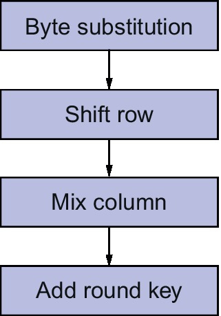
After an open competition, the Rijndael algorithm was chosen as the winner and implemented as the AES standard. Rijndael allows key and block sizes to be 128, 192, or 256 bits. AES allows the same key sizes, but operates using a block size of 128 bits. The algorithm operates in a similar way to DES, with 10 rounds of confusion and diffusion operators (shuffling and mixing) blocks at a time. Each round has a separate key, generated from the overall key. The round structure is shown in Figure 10.7.
The overall AES structure is given in Figure 10.8.
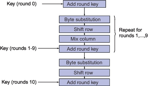
Each block consists of 128 bits, and these are divided into 16 8-bit bytes. Each of the operations acts upon these 8-bit bytes in a 4 × 4 matrix:
Note that each element (ai,j) is an 8-bit byte, viewed as elements of GF(28). The arithmetic operators take advantage of the Galois Field (GF) rules defined in the Rijndael algorithm; an example is that of addition that is implemented by XOR.
Multiplication is more complicated, but each byte has the multiplicative inverse such that b.b′ = 00000001 (apart from 00000000, whose multiplicative inverse is 00000000). The model of the finite field GF(28) depends on the choice of an irreducible polynomial of degree 8, which for Rijndael is:
Each of the round operations requires a specific mathematical exploration. Taking each in turn we can establish the requirements for each one.
Taking the original matrix:
each element can be replaced byte-by-byte to generate a new matrix:

Byte substitution requires that for each input data block a(3,3), we look up a table of substitutions and replace the bytes to produce a new matrix b(3,3). The way it works is that for each input byte abcdefgh, we look up row abcd and column efgh and use the byte at that location in the output.
The complete byte substitution table is defined as shown in Figure 10.9.
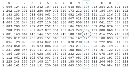
For example: If the input data byte was 7A, then this in binary terms is:
So the row required is 7 (0111) and the column required is A (1010). From this we can read off the resulting number from the table:
This is illustrated in the byte substitution table in Figure 10.9.
We can see that this is a bit shuffling operation that is simply moving bytes around in a publicly defined manner that does not have anything to do with a key.
Also note that the individual bits within the byte are not changed as such. This is a bytewise operation. The Shift Row function is essentially a set of cyclic shifts to the left with offsets of 0, 1, 2, 3, respectively.
The Mix Columns function is a series of specific multiplications:
where 01 = 00000001, 02 = 00000010, 03 = 00000011.
All multiplications are GF(28) and this transformation is invertible.
The final operation in each round is to add the key using the following function:
The round keys are generated using the following method. The original key of 128 bits is represented as a 4 × 4 matrix of bytes (of 8 bits). This can be thought of as four columns W(0),W(1),W(2),W(3). Adjoin 40 columns W(4),…,W(43). The round key for round i consists of i columns. If i is a multiple of 4:
where T is a transformation of a, b, c, d in column W(i − 1) using the following procedure:
• Shift cyclically to get b, c, d, a.
• Replace each byte with S-box entry using ByteSub, to get e, f, g, h.
• Compute round constant r(i) = 00000010(i − 4)/4 in GF(28).
• T(W(i − 1)) = (e ⊕ r(i),f,g,h)
• If i is not a multiple of 4, W(i) = W(i − 4) ⊕ W(i − 1)
10.4.1 Implementing AES in VHDL
We have two options for implementing block cipher operations in VHDL. We can use the structural approach (shown in the DES example previously in this chapter), or sometimes it makes sense to define a library of functions and use those to make much simpler models.
In the example of AES, we can define a top level entity and architecture that has the bare minimum of structure and is completely defined using functions. This can be especially useful when working with behavioral synthesis software as this allows complete flexibility for architectural optimization.
In this example, we have the plaintext and keytext inputs defined as 128-bit-wide vectors and the ciphertext output is also defined as 128 bits wide. The go flag initiates the encryption and the done flag shows when this has been completed.
Notice that we have a work library defined called aes_functions which encapsulates all the relevant functions for the AES algorithm. The set of functions is defined in a package (aes_functions) and the VHDL is given:
After the functions and top level entity have been defined, we can implement a test bench that applies a set of test data to the inputs and verifies that the correct output has been obtained. Notice that we use the assertion technique to identify correct operation.
10.5 Summary
This chapter shows how standard block ciphers can be implemented in VHDL and Verilog using DES as an example. AES has been developed further using VHDL, but can use the same principles in Verilog. Both of these algorithms are in common usage today and in operational hardware. There are numerous other methods, as security requires a constant evolution of encryption techniques and no doubt more robust and secure methods will emerge that require implementation in VHDL and/or Verilog in the future.