
Behavioral Modeling in using HDLs
Abstract
This chapter introduces the concept of behavioral modeling. There is a real need to abstract to a higher level in many designs to make the overall system level design easier. There is less need to worry about details of implementation at the system level if the design can be expressed behaviorally, especially if the synthesis method can handle any clock, partitioning or implementation issues automatically. Using system level, or behavioral, analysis, decisions can be made early in the design process so that potentially costly mistakes can be avoided. Preliminary area and power estimates can be made and key performance specifications and architectural decisions can be made using this approach, without requiring to have detailed designs for every block.
17.1 Introduction
There is a real need to abstract to a higher level in many designs to make the overall system level design easier. There is less need to worry about details of implementation at the system level if the design can be expressed behaviorally, especially if the synthesis method can handle any clock, partitioning, or implementation issues automatically.
Furthermore, by using system level, or behavioral, analysis, decisions can be made early in the design process so that potentially costly mistakes can be avoided. Preliminary area and power estimates can be made and key performance specifications and architectural decisions can be made using this approach, without requiring to have detailed designs for every block.
17.2 How to Go from RTL to Behavioral HDL Descriptions
The abstraction from an RTL (Register Transfer Level) hardware description language (HDL) to behavioral is straightforward in one sense, in that the resulting HDL (whether Verilog or VHDL) is actually simpler. There is no need to ensure that correct clocking takes place, or that separate processes are implemented for different areas of the architecture, or even separate components instantiated.
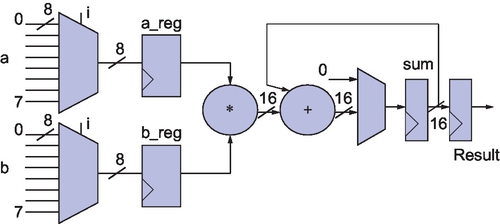
It is useful to consider an example to illustrate this point by looking at the difference between the RTL and behavioral HDL in an example such as a cross product multiplier. In this case we will demonstrate the RTL method and then show how to abstract to a behavioral model. First, consider the specification for the model in Figure 17.1, which has the data path model as shown in Figure 17.2.

17.3 Implementing the Behavioral Model using VHDL
The first task is to define the types for the VHDL for the entity of the model and this is shown in the following code. Notice that we have defined a new type, sig8, that is a signed type and a vector based on this for the cross product multiplications.
The entity can now be put together and is shown as follows. Notice that for RTL we require both a clock and a reset.
The basic architecture can be set up with the basic internal signals defined, and the processes will be explained separately.
Notice that there are two processes, one for the accumulation and the other to handle the multiplication. One important aspect is that it is not immediately obvious what is going on. Even in this simple model it is difficult to extract the key behavior of the state machine. In a complex controller it verges on the impossible unless the structure is well known and understood, which is an important lesson when using any kind of synthesis tool using VHDL or Verilog at any level.
Now reconsider using behavioral VHDL instead. The model uses the same packages and libraries as the RTL model; however, notice that there is no need for an explicit clock or reset.
In this model, the architecture becomes much simpler and can be modeled in a much more direct way than the RTL approach.
Notice that it is much easier to observe the functionality of the model and also the behavior can be debugged more simply than in the RTL model. The design is obvious, the code is readable and the function is easily ascertained. Note that there is no explicit controller; the synthesis mechanism will define the appropriate mechanism. Also notice that the model is defined with a single process. The synthesis mechanism will partition the design depending on the optimization constraints specified.
Note the wait statement. This introduces an implicit clock delay into the system. Obviously this will depend on the clock mechanism used in reality. There is also an implied reset. If an explicit clock is required then use a wait until rising_edge(clk) or similar approach, while retaining the behavioral nature of the model.
17.4 Implementing the Behavioral Model using Verilog
As before, the model (in this case a Verilog module) can now be put together and is shown here. Notice that for RTL we require both a clock and a reset.
Again, even with Verilog which generally has a little simpler syntax than VHDL, in this simple model it is difficult to extract the key behavior of the state machine. In a complex controller it verges on the impossible unless the structure is well known and understood, which is an important lesson when using any kind of synthesis tool using VHDL or Verilog at any level.
Now reconsider using behavioral code instead. The model uses the same packages and libraries as the RTL model; however, notice that there is no need for an explicit clock or reset.
Notice that it is much easier to observe the functionality of the model and also the behavior can be debugged more simply than in the RTL model. The design is obvious, the code is readable and the function is easily ascertained. Note that there is no explicit controller, as the synthesis mechanism will define the appropriate mechanism. Also notice that the model is defined with a single module. The synthesis mechanism will partition the design depending on the optimization constraints specified. This is easily parameterized, modified and clear.
17.5 Summary
Behavioral modeling is a useful technique for both initial design ideas and also as the starting point for an RTL design. It is important to remember, however, that quite a lot of behavioral HDL cannot be synthesized and is therefore purely for conceptual design or use in test benches. In order to make this a practically useful design tool, the designer can take advantage of the ability of VHDL to have numerous architectures, or Verilog to have numerous submodules, and, by using the same test bench, validate the RTL against the behavioral model to ensure correctness.
In summary, we can use behavioral modeling early with high impact to:
• Carry out fast functional simulation;
• Make performance criteria/ Design trade-offs;
• Investigate nonlinear effects;
• Look at implementation issues;
• Carry out topology evaluation.