
Design Optimization Example
DES
Abstract
Elsewhere in this book the basics of design optimization are discussed, but in general these are at an RTL level. The use of behavioral modeling has also been described, but in general the use of high-level behavioral synthesis is still rarely used in practice. In this chapter, the use of behavioral synthesis is investigated as an alternative to create optimal designs rather than using an RTL approach.
This chapter describes the experience of designing an example using a high level behavioral synthesis system.
19.1 Introduction
Elsewhere in this book the basics of design optimization are discussed, but in general these are at an RTL level. The use of behavioral modeling has also been described, but in general the use of high-level behavioral synthesis is still rarely used in practice. In this chapter, the use of behavioral synthesis is investigated as an alternative to create optimal designs rather than using an RTL approach.
This chapter describes the experience of designing a Data Encryption Standard (DES) core in Electronic Code Book (ECB) mode using a high-level behavioral synthesis system. The main objective was to write a high-level language description that was both readable and synthesizable. The secondary objective was to explore the area/delay design space of both single and triple DES. The designs were simulated using both the pre-synthesis (behavioral) and post-synthesis (RTL) VHDL, verifying that the outputs were not only the same, but were the expected outputs defined in the test set.
In this chapter, the high-level code has been written in VHDL as the MOODS software only supports VHDL input; therefore there is not a direct Verilog equivalent.
It should be pointed out that there are now more options for the designer than ever before for high-level modeling, including C; however, behavioral VHDL or Verilog is still relatively straightforward to design at the same time as RTL code, as the simulations are easy to manage (and in fact often the same entity could be used, but with different architectures). System-C has become useful for high-level modeling, particularly when coding is involved. However, the ability for hardware designers to handle more architectural issues in addition to the behavioral model still makes behavioral HDL modeling a useful tool.
19.2 The Data Encryption Standard
The Data Encryption Standard, usually referred to by the acronym DES, is a well-established encryption algorithm which was first standardized by NIST in the 1980s. It is described in detail earlier in this book, in Chapter 10, so only the basic information about the algorithm is presented here.
While DES has largely been superseded by the AES (Advanced Encryption Algorithm) it is now common to find the algorithm being used in triplicate (an algorithm known as Triple-DES or TDES for short). This algorithm uses the same DES core, but uses three passes with different keys. DES was designed to be small and fast, and the algorithm is mainly based on shuffling and substitution. There is very little computation involved, which makes it ideal for hardware implementation.
19.3 MOODS
MOODS (Multiple Objective Optimization in Control and Datapath Synthesis) is a high-level behavioral synthesis suite developed at the University of Southampton. It takes as input high-level behavioral VHDL and transforms this into structural VHDL that is behaviorally equivalent. MOODS uses optimization and design space exploration to obtain suitable RTL designs to meet the designer’s constraints and requirements.
An optimizer is used to convert the behavioral VHDL into a form that can be described using a simple dataflow graph (DFG) which allows the control flow to be optimized. This is effectively a state machine that can be easily converted into RTL VHDL. The optimization of this with respect to area can be achieved by sharing data units (such as registers) using multiplexing and with respect to delay by combining data units to reduce the number of clock cycles required.
19.4 Initial Design
19.4.1 Introduction
The overall structure of the DES algorithm is shown in Figure 19.1.
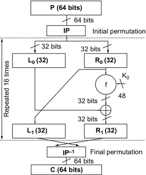
The core algorithm is repeated 16 times with a different subkey for each round. These subkeys are 48 bits long and are generated from the original 56-bit key. The algorithm was converted directly to VHDL using a functional decomposition style (i.e., functions were created to represent each equivalent function in DES).
19.4.2 Overall Structure
The first stage in this design was to create an entity and an architecture with the required inputs and outputs and a single process containing the overall algorithm. This resulted in the VHDL outline here:
This process is a direct implementation of the main DES routine. The only implementation-specific feature is that the model waits for the signal go to be raised before starting processing and it raises the signal done at the end of processing, implementing a basic handshaking protocol.
This algorithm requires the two functions key_reduce and des_core. The former strips the parity bits from the key and the latter then implements the whole DES algorithm. The key_reduce function reduces the key from 64 to 56 bits and permutes the bits to form the initial state of the subkey:
The compiler directive –moods inline causes the synthesizer to inline the function. This allows the optimizer more scope for optimization of the circuit. The des_core function applies the basic DES algorithm 16 times on a slice of the data using a different subkey on each iteration:
The DES algorithm is made up of the key transformation functions key_rotate and key_compress, and the data transformation functions initial_permutation, f and final_permutation.
19.4.3 Data Transformations
The data transformations initial_permutation and final_permutation are simply hard-wired bit-swapping routines implemented using concatenation.
The f function is the main data transform, which is applied 16 times to the rightmost half, a 32-bit slice, of the data path. It takes as its second argument a 48-bit subkey generated by the key_compress function.
The function first takes the 32-bit slice of the datapath and expands it into 48 bits using the expand function. The expand function is again just a rearrangement of bits; input bits are replicated in a special pattern to expand the 32-bit input to the 48-bit output.
This expanded word is then exclusive-ORed with the subkey and fed into a substitute block. This substitutes a different 4-bit pattern for each 6-bit slice of the input pattern (remember that the original input has been expanded from 32 bits to 48 bits, so there are eight substitutions in all). The substitution also has the effect of reducing the output back to 32 bits again. The substitute algorithm first splits the input 48 bits into eight 6-bit slices. Each slice is then used to lookup a substitution pattern for that 6-bit input. This structure is known as the S-block. In the initial implementation, a single ROM is used to store all the substitution patterns. The substitution combines a block index with the input data to form an address, which is then used to lookup the substitution value in the S-block ROM. This address calculation is encapsulated in the smap function.
The eight substitutions are carried out by the eight calls to smap in the substitute function.
The final stage of the datapath transform is the permute function, which is another bit-swapping routine:
These functions define the whole of the datapath part of the algorithm.
19.4.4 Key Transformations
The encryption key also needs to be transformed a number of times—specifically, before each data transformation, the key is rotated and then a smaller subkey is extracted by selecting 48 of the 56 bits of the key. The rotation is the most complicated part of the key transformation. The 56-bit key is split into two halves and each half rotated by 0, 1, or 2 bits depending on which round of the DES algorithm is being implemented. The direction of the rotation is to the left during encryption and to the right during decryption. The algorithm is split into two functions: do_rotate which, as the name suggests, does the rotation, and key_rotate which calls do_rotate twice, once for each half of the key. The do_rotate function uses a ROM to store the rotate distances for each round, numbered from 0 to 15:
The key_rotate function simply calls the previous function twice:
Finally, the key compression function key_compress selects 48 of the 56 bits to pass to the S-block algorithm.
19.5 Initial Synthesis
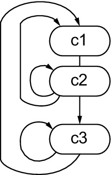
The design was synthesized by MOODS with delay prioritized first and area prioritized second. The target technology was the Xilinx Virtex library. Figure 19.2 shows the control state machine of the synthesized design. The whole state sequence represents the process, which is a loop as shown by the state transition from the last state (c11) back to the first (c1).

The first two states c1 and c2 implement the input handshake on signal go to trigger the process. The DES core is implemented by the remaining states, namely states c3 to c11, which are in the main loop as shown by the state transition back from c11 to c3, so are executed 16 times. There are nine states in this inner loop, giving a total algorithm length of 146 cycles, including the two states required for the input handshake and 144 for the DES core itself. However, an inspection of the original structure shown in Figure 19.1 suggests that a reasonable target for the inner loop is 2 cycles per round with an optimistic target of 1 cycle. Clearly there is a problem with this design. The synthesis software predicts that this design has the area and delay characteristics shown in Table 19.1 in the line labeled (1).
19.6 Optimizing the Datapath
Examining the nine control states in the main loop and relating these to the mapping of the control graph to the dataflow graph showed that the last 8 cycles were performing the S-block and the first 2 cycles were mainly related to transforming the key. The second state is an overlap state where both key and data transforms are taking place. The problem with the last 8 cycles was fairly self-evident since there are eight substitutions and there are eight control states to perform them. Clearly there was something causing each substitution to be locked into a separate control state and therefore preventing optimization with respect to latency. It wasn’t difficult to see what each of these states contained: just register assignments, concatenations and a ROM read operation. It is the last of these that is the problem; the ROM implementation being targeted is a synchronous circuit, so the S-block ROM can only be accessed once per clock cycle—in other words once per control state. It is this that is preventing the datapath operations from being performed in parallel. Attacking this problem is beyond the capabilities of behavioral synthesis because it requires knowledge of the dataflow at a much higher level than can be automatically extracted. The solution therefore requires modification of the original design.
There are two obvious solutions to this problem: either split the S-block into eight smaller ROMs that can therefore be accessed in parallel or make the S-block a non-ROM so that the array gets expanded into a decoder block once for each access, giving eight decoders. The latter solution appears simplest, but it will result in eight 512-way decoders, which will be a very large implementation. The solution of splitting the ROMs is more likely to yield a useful solution. The substitute function was rewritten to have eight mini-ROMs:
This was resynthesized and resulted in the control graph shown in Figure 19.3. The inner loop was found to have been reduced to two states, and examination of the last state confirmed that all of the S-block substitutions were being carried out in the one state c4. The key transformations were still split across the two inner states c3 and c4.

One interesting side-effect of this optimization is that it is also a smaller design. MOODS predicts that this design has the area and delay characteristics shown in Table 19.1 in the line labeled (2).
19.6.1 Optimizing the Key Transformations
Examination of the two control states in the main loop, which both contain key transformations, showed that both of these states were performing ROM access and rotate operations. Examination of the original key_rotate function showed that the shift distance ROMs are accessed twice per call, so this turned out to be exactly the same problem as with the S-block ROM. Since ROMs are synchronous, they can only be accessed once per cycle and this forces at least two cycles to be used for the rotate. To solve this, the function can be rewritten to only access the ROMs once per call:
This was resynthesized and resulted in the control graph shown in Figure 19.4. The inner loop was found to have been reduced to one state (c3) containing both the key and data transformations, which are repeated 16 times. As before, states c1 and c2 implement the input handshake.
So, this optimization means that the target of 1 clock cycle per round of the core was achieved. MOODS predicts that this design has the area and delay characteristics shown in Table 19.1 in the line labeled (3).
19.7 Final Optimization
It was recognized that the key_rotate function could be simplified by rethinking the rotate algorithm such that a right rotate of 1 bit was replaced by a left rotate of 27 bits (for a 28-bit word). This eliminates a conditional statement, which it was felt could be preventing some optimizations from taking place. This means that there was no need to have a different algorithm for encryption and decryption. This led to the following rework:
The state machine for this design was basically the same as for the previous design as shown in Figure 19.4. It was found that this version was slightly slower than the previous design but significantly smaller. MOODS predicts that this design has the area and delay characteristics shown in Table 19.1 in the line labeled (4).
19.8 Results
The results predicted by MOODS for all the variations of the design discussed so far are summarized in the following table:
Table 19.1
Physical metrics for single DES designs
| Design | Area (Slices) | Latency (Cycles) | Clock (ns) | Throughput (MB/s) |
| (1) Initial design | 552 | 146 | 7.8 | 7.12 |
| (2) Optimized S blocks | 426 | 34 | 7.1 | 35.2 |
| (3) Optimized key | 489 | 18 | 7.1 | 62.6 |
| (4) Optimized branch | 307 | 18 | 8.4 | 52.9 |
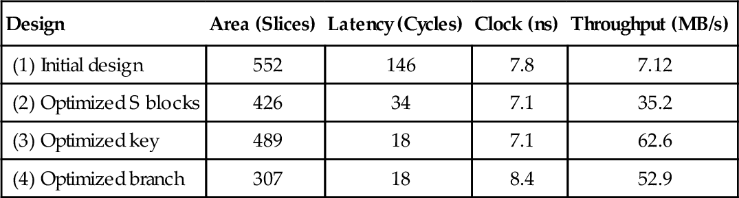
It can be seen that design (3) is the fastest, but design (4) is the smallest. Figure 19.5 plots area vs. throughput for these four designs. The X-axis represents the area of the design and the Y-axis the throughput.

19.9 Triple DES
19.9.1 Introduction
Building on this, the DES core developed previously was used as the core for a Triple-DES implementation. The idea of triple DES is that data is encrypted three times. The rationale for choosing three iterations and the advantages and disadvantages of this are explained in [5]. A common form of Triple DES is known as EDE2, which means data is encrypted, decrypted and then encrypted again using two different keys. The first key is used for both encryptions and the second key for the decryption. There are obviously a number of different trade-offs that can be made in this design. Each of these is examined in the following sections. In all cases, the smallest implementation (design (4)) was used as the DES core.
19.9.2 Minimum Area Iterative
To achieve a minimum area implementation, a single DES core is used for all three stages. The data is passed through this core three times with the different permutations of keys and encryption mode to achieve the EDE2 algorithm. Two different styles of VHDL were tried. These differed in the method used to select the different inputs for each encryption step. The first style used a case statement and the second style used indexed arrays. The case statement style results in the following VHDL design:
It can be seen that this uses a case statement to select the appropriate key and encryption mode for each iteration. The characteristics of the case statement solution are shown in Table 19.2 in the line labeled (5). The core DES algorithm accounts for 48 cycles (3 iterations of 16 rounds with 1 cycle per round), leaving an additional overhead of 3 cycles. This additional 3 cycles is due to the case statement selection of the key, which adds an extra cycle per iteration of the core. The second style uses arrays to store the keys and modes and then indexes these arrays to set the key and mode for each iteration. The process becomes:
It was found that the latency was the same as the case statement solution but the area was approximately 25% larger. This overhead is mostly due to the use of the register arrays, which add up to about 200 extra flip-flops. Clearly the case statement design is the most efficient of the two and so this solution was kept and the array style solution discarded.
19.9.3 Minimum Latency Pipelined
To achieve minimum latency between samples, three DES cores are used to form a pipeline. Data samples can then be fed into the pipeline every 18 cycles (the latency of the single core), although the time taken for a result to be generated is 50 cycles because of the pipeline length. The circuit is simply three copies of the single-DES process:
Note how the done output is driven only by one of the cores; this will give the right result provided all three cores synthesize to the same delay, which in practice they will. This design decision alleviates the need to have handshaking between the cores. MOODS predicts that this design has the area and delay characteristics shown in Table 19.2 in the line labeled (6). The state machine in Figure 19.6 shows the three independent processes. For example, the first process is represented by states c2, c3, and c4. The first two states perform the handshaking on go and c4 implements the DES core with its 16 iterations. State c7 is the second DES core and c10 the third.
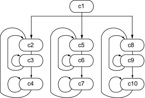
Table 19.2
Predicted Results for MOODS, Leonard and Foundation Tools.
| Design | Tool | Area (slices) | Latency (cycles) | Clock (ns) | Throughput (MB/s) |
| (4) | MOODS | 307 | 18 | 8.4 | 52.9 |
| DES | Leonardo | 258 | 13.4 | 33.2 | |
| Foundation | 274 | 18.4 | 24.2 | ||
| (5) | MOODS | 500 | 53 | 8.4 | 18.0 |
| Iterative | Leonardo | 381 | 13.7 | 11.0 | |
| TDES | Foundation | 422 | 17.8 | 8.5 | |
| (6) | MOODS | 920 | 18 | 8.4 | 52.9 |
| Pipelined | Leonardo | 774 | 13.7 | 32.4 | |
| TDES | Foundation | 826 | 18.4 | 24.2 |

19.10 Comparing the Approaches
The physical metrics of the previous section are the predicted values given by MOODS. To get a more accurate assessment of the design, RTL synthesis of the structural VHDL output of MOODS is required. This was carried out using Mentor Graphics Leonardo Spectrum RTL synthesis suite. These results can be finessed further by carrying out placement and routing using the Xilinx Integrated Software Environment (ISE) Foundation suite. The results predicted by all three tools (MOODS, Leonardo and Foundation) for the three approaches (DES, Iterative TDES and Pipelined TDES) are shown in Table 19.2. In all cases, the design was optimized during RTL synthesis using the vendors’ default optimization settings—a combination of area and delay optimization—with maximum optimization effort. Placement and routing was performed with an unreachable clock period to force Foundation to produce the fastest design.
This shows that MOODS tends to overestimate the area of the design and underestimate the delay. Both of these are expected outcomes. The tendency to overestimate area is because it isn’t possible to predict the effect of logic minimization when working at the behavioral level. The tendency to underestimate delay is because it isn’t possible to predict routing delays.
19.11 Summary
This chapter has shown that it is possible to design complex algorithms such as DES using the abstraction of high-level VHDL and get a synthesizable design. However, the synthesis process is not and cannot ever be fully automated—human guidance is still necessary to optimize the design’s structure to get the best from the synthesis tools. Nevertheless, the modifications are high-level design decisions and the final design is still readable and abstract. There has been no need to descend to low-level VHDL to implement DES. The implementations of Triple-DES show how VHDL code can easily be reused when written at this level of abstraction. It is quite an achievement to implement the DES and two implementations of the Triple-DES algorithm in four working days, including testing, and this demonstrates the kind of productivity that results from the application of behavioral synthesis tools.
For more details of the analysis of these techniques, the reader is referred to the technical papers [1–3].