
Finite State Machines in VHDL and Verilog
Abstract
Finite State Machines (FSMs) are at the heart of most digital design. The basic idea of an FSM is to store a sequence of different unique states and transition between them depending on the values of the inputs and the current state of the machine. The FSM can be of two types Moore (where the output of the state machine is purely dependent on the state variables) and Mealy (where the output can depend on the current state variable values AND the input values).
22.1 Introduction
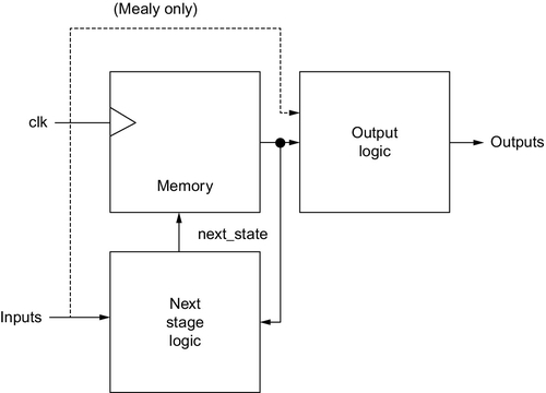
Finite State Machines (FSMs) are at the heart of most digital design. The basic idea of an FSM is to store a sequence of different unique states and transition between them depending on the values of the inputs and the current state of the machine. The FSM can be of two types: Moore (where the output of the state machine is purely dependent on the state variables) and Mealy (where the output can depend on the current state variable values AND the input values).1 The general structure of an FSM is shown in Figure 22.1:
22.2 State Transition Diagrams
One method of describing Finite State Machines from a design point of view is using a state transition diagram (bubble chart) which shows the states, outputs and transition conditions.2 A simple state transition diagram is shown in Figure 22.2.
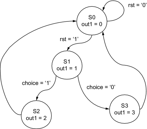
Interpreting this state transition diagram, it is clear that there are four bubbles (states). The transitions are controlled by two signals (rst and choice), both of which could be represented by bit or std_logic types (or another similar logic type). There is an implicit clock signal, which we shall call clk and the single output out1.
22.3 Implementing Finite State Machines in VHDL
This transition diagram can be implemented using a case statement in a process using the following VHDL:
It must be noted that not all state machines will neatly have a number of states exactly falling to a power of 2, and so unused states must also be managed using the “when-others” approach described elsewhere in this book.
It is also the case that the two processes can be combined into a single process, which can reduce the risk of glitches being introduced by the synthesis tools, especially from incorrect assignments. It can also make debugging simpler.
22.4 Implementing Finite State Machines in Verilog
The transition diagram can also be implemented in Verilog, again using two case statements (one for the state transitions and one for the outputs):
22.5 Testing the Finite State Machine Model
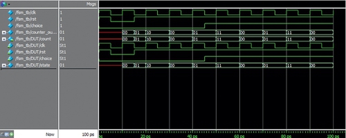
Whether the VHDL or Verilog is being used, a test bench is required to evaluate the behavior and check that it is correct. In this example, Verilog has been used, but the principle is the same for both HDLs. The idea is to reset the FSM, then clock through the sequence with choice = 0 (which will go from state S0 to S1 and then S2, returning to S0), and then the choice is set to 1, and this time the sequence will go from state S0 to S1 and then S3, returning to S0. The output variable (counter_output) shows the state number as an output. The simulation is shown in Figure 22.3.
22.6 Summary
Finite State Machines are a fundamental technique for designing control algorithms in digital hardware. This chapter of this book is purely an introduction to the key concepts and if the reader is not already fully familiar with the basic concepts of digital hardware design, you are encouraged to obtain a standard text on digital design techniques to complement the practical implementation methods described in this book.