4.4. STEADY-STATE CONDUCTION AND SHAPE FACTORS
4.4A. Introduction and Graphical Method for Two-Dimensional Conduction
In previous sections of this chapter we discussed steady-state heat conduction in one direction. In many cases, however, steady-state heat conduction is occurring in two directions, that is, two-dimensional conduction is occurring. The two-dimensional solutions are more involved and in most cases analytical solutions are not available. One important approximate method for solving such problems is to use a numerical method discussed in detail in Section 4.15. Another important approximate method is the graphical method, which is a simple method that can provide reasonably accurate answers for the heat-transfer rate. This method is particularly applicable to systems having isothermal boundaries.
In the graphical method we first note that for one-dimensional heat conduction through a flat slab (see Fig. 4.2-1) the direction of the heat flux or flux lines is always perpendicular to the isotherms. The graphical method for two-dimensional conduction is also based on the requirement that the heat-flux lines and isotherm lines intersect each other at right angles while forming a network of curvilinear squares. This means, as shown in Fig. 4.4-1, that we can sketch the isotherms and also the flux lines until they intersect at right angles (are perpendicular to each other). With care and experience we can obtain reasonably accurate results. General steps to use in this graphical method are as follows:
1. | Draw a model to scale of the two-dimensional solid. Label the isothermal boundaries. In Fig. 4.4-1, T1 and T2 are isothermal boundaries. |
2. | Select a number N that is the number of equal temperature subdivisions between the isothermal boundaries. In Fig. 4.4-1, N = 4 subdivisions between T1 and T2. Sketch in the isotherm lines and the heat-flow or -flux lines so that they are perpendicular to each other at the intersections. Note that isotherms are perpendicular to adiabatic (insulated) boundaries and also lines of symmetry. |
3. | Keep adjusting the isotherm and flux lines until for each curvilinear square the condition Δx = Δy is satisfied. |
Figure 4.4-1. Graphical curvilinear-square method for two-dimensional heat conduction in a rectangular flue.

In order to calculate the heat flux using the results of the graphical plot, we first assume unit depth of the material. The heat flow q' through the curvilinear section shown in Fig. 4.4-1 is given by Fourier's law:
Equation 4.4-1
![]()
This heat flow q' will be the same through each curvilinear square within this heat-flow lane. Since Δx = Δy, each temperature subdivision ΔT is equal. This temperature subdivision can be expressed in terms of the overall temperature difference T1 − T2 and N, the number of equal subdivisions:
Equation 4.4-2
![]()
Also, the heat flow q' through each lane is the same, since Δx = Δy in the construction and in Eq. (4.4-1). Hence, the total heat transfer q through all of the lanes is
Equation 4.4-3
![]()
where M is the total number of heat-flow lanes as determined by the graphical procedure. Substituting Eq. (4.4-2) into (4.4-3),
Equation 4.4-4
![]()
EXAMPLE 4.4-1. Two-Dimensional Conduction by Graphical ProcedureDetermine the total heat transfer through the walls of the flue shown in Fig. 4.4-1 if T1 = 600 K, T2 = 400 K, k = 0.90 W/m · K, and L (length of flue) = 5 m. Solution: In Fig. 4.4-1, N = 4 temperature subdivisions and M = 9.25. The total heat-transfer rate through the four identical sections with a depth or length L of 5 m is obtained by using Eq. (4.4-4):
|
4.4B. Shape Factors in Conduction
In Eq. (4.4-4) the factor M/N is called the conduction shape factor S, where
Equation 4.4-5
![]()
Equation 4.4-6
![]()
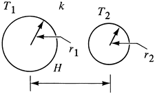
This shape factor S has units of m and is used in two-dimensional heat conduction where only two temperatures are involved. The shape factors for a number of geometries have been obtained and some are given in Table 4.4-1.
| Cylinder of length L in a square |  | |
| Horizontal buried cylinder of length L |  | |
| Two parallel cylinders of length L |  |  |
| Sphere buried |  |  |
[*] The thermal conductivity of the medium is k.
For a three-dimensional geometry such as a furnace, separate shape factors are used to obtain the heat flow through the edge and corner sections. When each of the interior dimensions is greater than one-fifth of the wall thickness, the shape factors are as follows for a uniform wall thickness Tw:
Equation 4.4-7

where A is the inside area of wall and L the length of inside edge. For a completely enclosed geometry, there are six wall sections, 12 edges, and eight corners. Note that for a single flat wall, q = kSwall(T1 − T2) = k(A/Tw)(T1 − T2), which is the same as Eq. (4.2-1) for conduction through a single flat slab.
For a long, hollow cylinder of length L such as that in Fig. 4.2-2,
Equation 4.4-8
![]()
For a hollow sphere, from Eq. (4.2-14),
Equation 4.4-9
![]()

