
Case Study 9: Metallurgical Analysis Used in Gas Turbine Maintenance and Extending TBOs21
Metallurgical evaluation of the post-service condition of turbine blades provides information needed to make informed maintenance decisions, maximize potential cost savings, and manage risk. Original engine manufacturers (OEM) provide maintenance guidelines for service interval periods and component repair recommendations.
However, the operating conditions between engine users and specific sites differ, resulting in a considerable variation in the extent of part deterioration and post-service condition. Therefore, characterization of the blade set condition can be used to optimize maintenance decisions and provide insight towards the potential of service interval extension.
The operating conditions of a gas turbine are such that deterioration of turbine blades is inherent and blades therefore have a finite operating life. Under ideal base load conditions, degradation of hot section components is primarily a function of operating temperature. In such conditions, the component life is generally based upon (a) the depletion of the protective coatings or surface oxidation and (b) strength degradation and creep damage of the base alloy. Thermal degradation is exponentially correlated to temperature and minor changes in temperature can have large effects upon the rate of deterioration. In peaking applications, engine starts generate thermal-mechanical fatigue damage. In combination, these mechanisms are considered by OEMs to predict damage accumulation and establish criteria used to determine the component life and service interval length.
Non-ideal conditions such as corrosive environments, over-firing, or impact damage can result in accelerated component deterioration. These modes of degradation may not be included within the OEM service interval length guidelines and, if they occur, may have implications relevant to the maintenance and repair of the blades. Identification of these issues can be used to generate corrective actions in order to minimize risk of component failure and maintaining the component reparability after each service interval.
Conversely, many units are operated at part-load conditions under which damage will accumulate more slowly and so the OEM lifing criteria may be conservative.
As an alternative to predicting the damage expected after a service interval, destructive metallurgical analysis allows complete characterization of the actual post-service condition. Life analysis refers to a metallurgical examination that characterizes the overall condition of a blade including the material state, coating degradation, and damage within the internal passages. The data collected from the analysis can be interpreted to:
a. Assess reparability of the blade set. Minimize risk of otherwise undetectable damage
b. Determine repair processes required to return the set to serviceable condition
c. Evaluate the performance and selection of the coatings (if applicable)
d. Provide indications of abnormal or detrimental engine operating conditions
This case will summarize the typical modes of deterioration found in metallurgical analysis of service exposed blades and present guidelines for using that information to make repair, maintenance, and engine operating decisions (Table 12–3).
TABLE 12–3
Summary of Degradation, Consequences and Maintenance Considerations
Metallurgical Analysis Procedure
The techniques used for life analysis are well established in literature and practice. One blade, which is either representative of the set or exhibits independent, unrepairable damage (such as impact damage), is selected for destructive examination. The initial steps include review of the blade history, visual examination, non-destructive testing, and gathering of relevant surface deposits.
The blade is typically sectioned to remove samples from the lower, mid and upper portions of the airfoil, the tip or shroud and any other features of interest. As the operating temperature of the root is below that at which material degradation occurs, a section of the root is examined to provide a pre-service material benchmark. The samples are prepared for microscopic examination by conventional metallographic polishing techniques.
The evaluation includes assessment of the base alloy microstructure, the coating/external surface condition, and the internal surface condition. Modes of degradation can be identified through various forms of microscopy and micro-analysis techniques. Depending on the size/design of the component, mechanical testing of the base metal may also be performed.
Base Metal Deterioration
Alloy Aging and Creep Damage
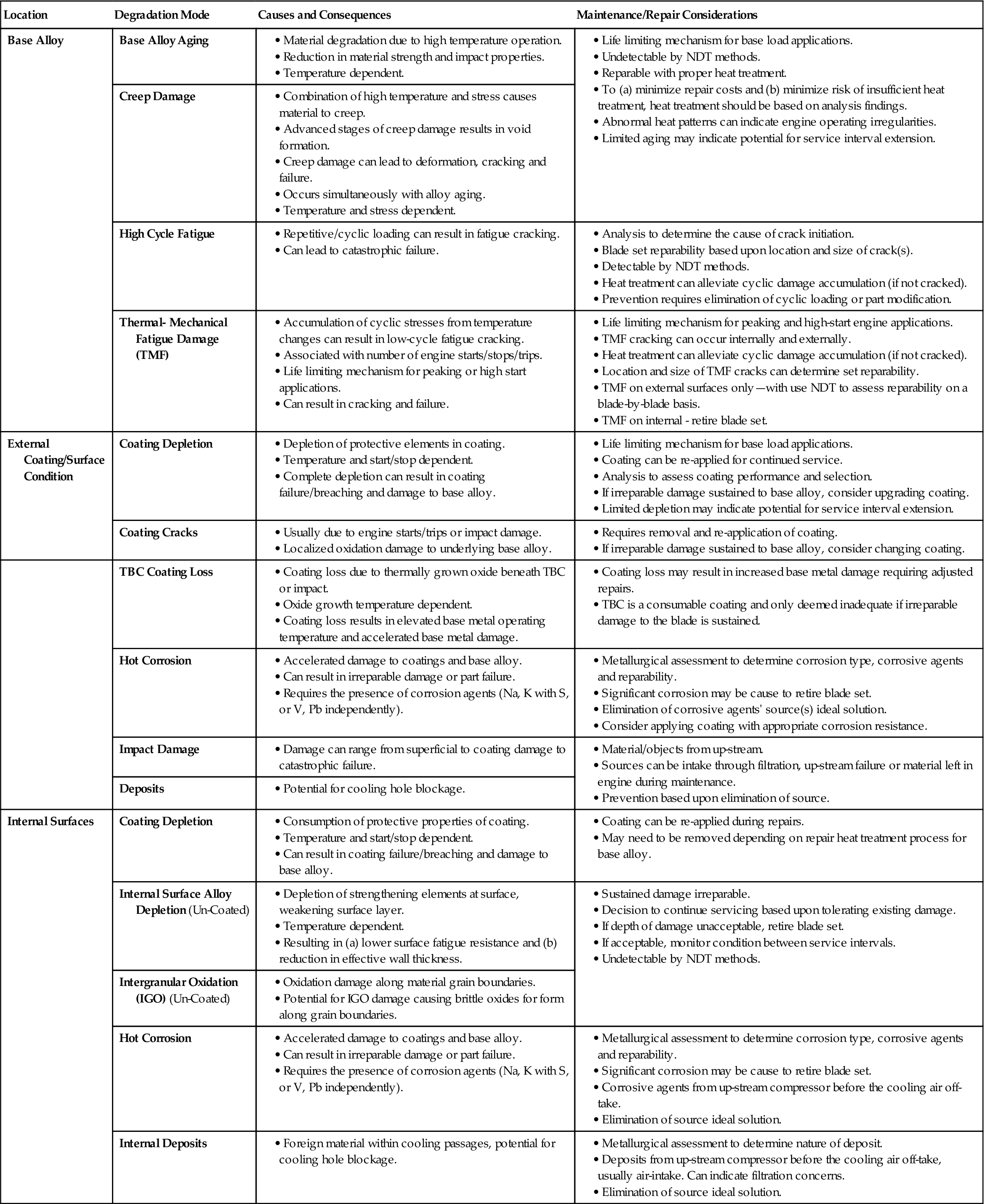
Turbine blades are manufactured from precipitation-hardened nickel-based superalloys that develop their high strength at high temperatures from gamma prime, Ni3Al precipitates within the material. In the as-new condition, the size, density and morphology of the gamma prime precipitates are optimized for maximum strength (Figure 12–24a). However, during operation at elevated temperatures, the microstructure undergoes various changes. The strengthening gamma prime precipitates spheroidize, enlarge and join, resulting in a reduction in material strength (Figure 12–24b and c). Topologically close-packed (TCP) phases can also form resulting in a dramatic loss of ductility and reduction in creep strength (Figure 12–25a). Microstructural degradation takes place by diffusion mechanisms and the rate of degradation is therefore a function of both time and component temperature.
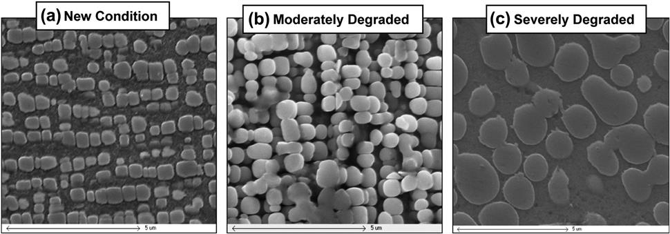
Due to the centrifugal loading and operating temperatures, the airfoil material also undergoes creep deformation. Creep is a diffusion-based mechanism correlated exponentially to temperature. Eventually, creep results in the formation of voids that link to cause creep cracking (Figure 12–25b). While the detection of creep voids is a reliable indicator of creep damage, in most alloys, voids only form after a large fraction of the creep life is exhausted and hence they may be absent even in significantly creep-damaged material. Prior to the formation of such voids, it is difficult to identify damage due to creep. Creep damage may be evident by reduced creep rupture life measured by mechanical testing; however, the effect is confounded with the aging effects.
Both creep and microstructural damage can be repaired through appropriate heat treatments. Knowledge of the material condition can be used to ensure the appropriate thermal processing is implemented to restore the material properties needed for continued service at minimal risk. Base material that exhibits creep damage requires hot isostatic pressing (HIP) at appropriate temperature and pressure to collapse creep voids that may have formed. Alloy degradation is corrected by heat treatments capable of fully restoring the microstructure and material strength.
As microstructural degradation occurs as a function of temperature, the condition of the base alloy provides a relative thermal map of the blade’s operating temperatures. Once a typical thermal profile has been benchmarked for a given blade design, abnormal engine operation affecting the operating temperature of the blade can be detected.
Examples include short-term excessive overheating, long-term overheating, and temperature profile shift.
The base alloy condition can also provide insight into the suitability of the service interval length. Gross microstructural damage or the presence of creep voiding can indicate an inappropriate service interval at the conditions exposed. In the absence of an identifiable cause, it would be recommended to shorten the service interval in future. Conversely, if only moderate base alloy deterioration is present, service interval extension could be considered.
High Cycle Fatigue Cracking
Repetitive loading at moderate stresses can result in the formation of fatigue cracks and potentially failure. These cracks are generally attributed to vibrations, rubs, or resonant frequency events. The stages of fatigue cracking include the accumulation of material damage, crack initiation, crack propagation, and then ultimately final failure. At the common frequencies experienced by gas turbines, cycles are accumulated rapidly.
Endurance limit cycles in the order of 107 can occur within hours or days. Therefore, parts are designed to avoid experiencing cyclic stress intensities or events that would result in fatigue crack formation.
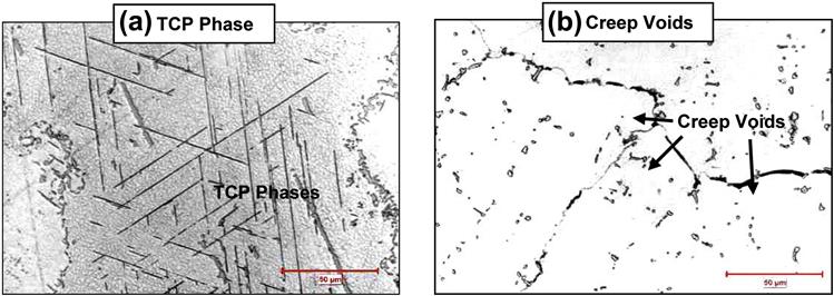
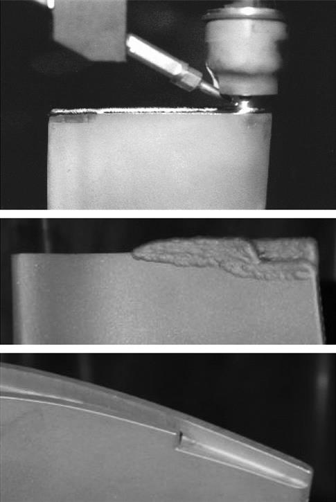
While NDT methods can detect cracking, metallurgical analysis is used to determine the nature of crack initiation (Figure 12.26) and to determine the reparability of the remainder of the blade set. Efforts are made to determine if crack initiation was due to an isolated cause (i.e., impact, material defect, etc.) or if the entire set was susceptible (i.e., resonant frequency). Once identified as fatigue cracking, further investigation as to the engine condition responsible for the elevated loading may be warranted.
Reparability is based upon the location and size/depth of the crack. Fatigue cracks generally initiate on the external surfaces and non-destructive techniques can be used to determine reparability blade by blade. Cracks at locations such as the root and the majority of the airfoil would be cause to retire the blade. In the case where the entire blade set was susceptible to fatigue cracking, appropriate heat treatments should be applied to alleviate accumulated, cyclic base metal damage.
Thermal-Mechanical Fatigue Damage
Temperature gradients in blades result from both rapid changes in the operating temperatures and steady state differences in temperature resulting from cooling effects.
These in turn can result in thermal-mechanical fatigue (TMF) damage from thermal stresses associated with the gradient. Repeated cycling can result in low-cycle fatigue crack initiation and propagation (an example of TMF is provided in Case Study 2, Figure 12–32). Therefore, thermal-mechanical damage often is the critical life limiting factor for engines with a high number of engine starts and trips. Damage is a function of part design, operating temperature, number of cycles, hours of operation between cycles, and temperature change rate.
When thermal-mechanical cracking is present only on the external surfaces, non-destructive testing can be used to sort reparable blades from irreparable. Blades that are deemed reparable should be subjected to appropriate heat treatments in order to alleviate accumulated material damage. As there is no reliable, non-destructive method to detect internal cracking, if metallurgical analysis detects internal cracking within the airfoil, the remainder of the blade set should be retired.
External Coating Condition
Aluminide/MCrAlY Coating Deterioration in Clean Environments
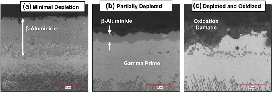
Diffusion and overlay coatings provide oxidation protection for operating environments for which the base alloy material does not have acceptable resistance. Oxidation resistance of coatings is principally based on aluminum content. The high aluminum content existing as β-aluminide forms a protective aluminum oxide layer slowing down the oxidation damage process. This process is exhaustive and once the aluminum content is depleted below a critical level, the β-aluminide transforms to gamma prime. At this point, a mixed oxide is formed that does not provide the same protective nature.
Figure 12–27 displays examples of coatings after service with minimal, moderate, and complete β-aluminide depletion. In simplification, the coating protective life is based upon the amount of β-aluminide remaining.
Coating breaches can occur due to either complete β-aluminide coating depletion or thermal-mechanical coating cracks (Figure 12–28). Generally, coating failure is deemed when the base alloy sustains oxidation damage that is either irreparable and/or increases the risk of failure to unacceptable levels.
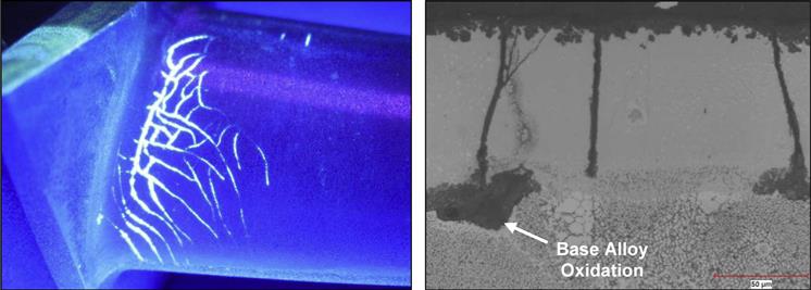
Optical examination of the coating is able to determine the amount of remaining β-aluminide in a coating, examine for cracks as well as oxidation damage to the coating and underlying base alloy. Data obtained from characterizing the coating/subsurface condition can be used to (a) assess if the coating provided adequate protection during previous service, (b) if inadequate, determine a more suitable coating based upon the damage mechanisms, and (c) assess if there is potential for service interval extension (incorporating other modes of damage).
On sets that the coating had failed to prevent damage to the base metal, the coating type, service interval, and operating conditions should be reviewed. In cases where the base alloy did not exhibit excessive alloy degradation, the coating may be defined as the primary life-limiting mechanism. In such cases, a coating upgrade may be beneficial.
Full depletion of the coating, combined with gross base alloy degradation, may suggest elevated operating temperatures or too long of a service interval at the operating conditions applied. If neither the coating nor any other form of degradation has approached their life limit, there may be the potential to increase the service intervals.
Thermal Barrier Coating Loss
Thermal barrier coatings (TBC) are applied to internally cooled blades to insulate the base metal from the hot gas environment. Due to their porous nature, TBCs are applied overtop of a diffusion or overlay coating called a “bond coat.” This bond coat provides the oxidation protection for the blade’s base metal.
TBC coating spallation is generally attributed to the formation of a brittle oxide layer between the TBC and the bond coat. Spallation occurs when this thermally grown oxide (TGO) reaches a critical thickness and thermal stresses cause the oxide layer to crack and spall. Figure 12–29 displays a TGO adjacent to the spalled region of the airfoil.
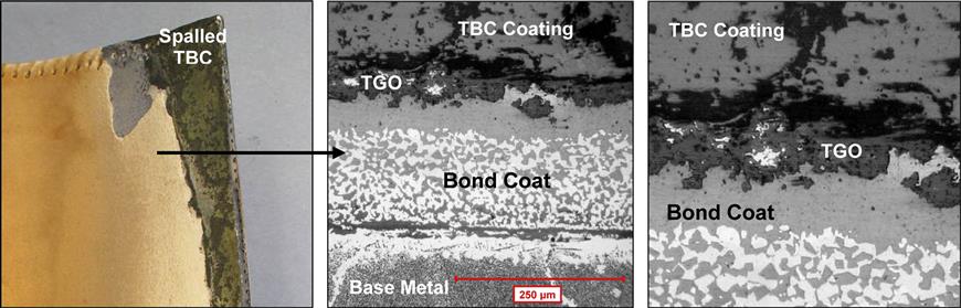
Formation of this TGO is a function of the bond coat’s oxidation resistance and operating temperature. Operating at higher temperatures increases the rate of TBC spallation initiation and continuation. Once TBC loss has initiated and no longer has the local insulation, neighboring coating loss is accelerated. TBC coating loss can also be initiated by impact damage. TBC coating loss by impact damage can be differentiated from TGO spallation by the sporadic nature of coating loss associated with impact damage.
Examination can determine the cause of coating loss and the extent of damage caused by the loss. Generally, TBC loss results in increased bond coat/surface and base alloy degradation due to a local elevated operating temperature. Repairs to the blade set may have to be adjusted pending the extent of base alloy damage. It should be noted that TBC coating is considered consumable and the coating performance is only considered to have been inadequate for service if the damage sustained to the blades is irreparable.
Hot Corrosion
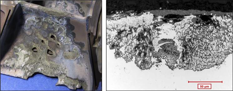
Hot corrosion is an accelerated attack of the coating and base metal that occurs due to the presence of contaminants in the hot gas environment. In particular, elements that can cause hot corrosion include sulfur combined with either sodium or potassium salts or, independently, vanadium and lead. Unlike in clean environments, the presence of these elements interferes with the formation of a protective oxide layer and accelerates the rate of attack.
Two broad classes of hot corrosion have been recognized, divided by the temperature ranges at which they occur. Type I hot corrosion occurs above 871°C while Type II occurs between 649 and 871°C. Although the mechanisms differ, the causes, implications, and preventive measures are similar.
Metallurgical analysis can identify the type of corrosion and elements present causing the hot corrosion. Ideally, the prevention of hot corrosion is by the elimination of corrosion agents at the source. Corrosive elements can originate through either fuel or air intake. Seawater humidity is a constant source of these salts and hot corrosion by these salts can indicate filtration inadequacies (see Figure 12–30).
A less ideal option but at times more feasible is applying coatings that provide corrosion protection. Overlay coatings consisting of the protective elements chromium and/or cobalt can provide some measure of protection to the base alloy. Platinum aluminide coatings also exhibit corrosion protection. Determination of the type of hot corrosion, elements causing corrosion and the extent of corrosion should be taken into account when selecting coatings for corrosion protection.
Impact Damage
Impact damage is the result of object(s) impacting blade(s) at high speeds. Sustained damage can range from insignificant to coating damage to catastrophic failure. Evidence of impact damage indicates concerns upstream of the turbine blades. Impact damage can be a symptom of upstream component(s) failure or filtration inadequacies. It can also point towards poor maintenance practices such as leaving equipment/objects within the gas path during shutdowns.
Metallurgical analysis can assess the extent of damage, both surface and subsurface, if the coating has been compromised. Information can be used to determine the reparability of the blade set. Due to the sporadic nature of impact damage, inspection methods can be developed to salvage blades from those that are irreparable.
Airfoil Deposits
Deposit build-ups on airfoils can reduce efficiency or provide an indication of an upstream issue. Indirect damage to the airfoil can be sustained from cooling holes becoming blocked. The origins of deposits can range from ingested material, parts rubbing or upstream failures (melted and adhered metal).
Determining the composition of deposits building up on turbine blades can provide insight as to the material origins. Similar to impact damage, deposits can indicate issues with filtration, upstream component failures, or objects left within the gas path during maintenance. Adhered airfoil deposits generally do not directly affect the reparability of a blade set.
Internal Surface Condition
Due to the inaccessibility and nature of damage incurred within the internal cooling passages, internal damage to the base alloy cannot be repaired. The decision to continue servicing the parts should include an evaluation of whether the existing internal damage can be tolerated. As non-destructive testing cannot detect the majority of internal damage modes, to determine whether a set of internally cooled blades can be safely returned to service requires a metallurgical life analysis.
Uncoated Internal Surfaces
Blades that are not internally coated can exhibit multiple forms of damage. Uncoated surfaces can experience alloy depletion at the surface. Base alloy elements such as aluminum and titanium can diffuse to the surface leaving behind a surface layer void of gamma prime (Figure 12–31a). Excessive thickness of this depleted area results in both reduced fatigue strength and a decrease in effective wall thickness when considering mechanical loading of the component. Note that the depleted material is indistinguishable by ultrasonic wall measurements. Metallurgical analysis is the only method to determine the remaining, effective wall thickness capable of sustaining service loading.
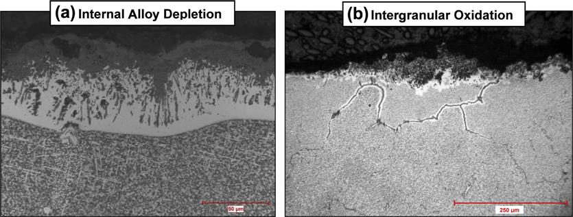
Other forms of oxidation damage that uncoated, internal surfaces are susceptible to are intergranular oxidation (IGO) and stress assisted grain boundary oxidation (SAGBO).
An example of IGO is presented in Figure 12–31b. Oxidation occurs along the base alloy grain boundaries resulting in oxide spikes into the material. These oxide spikes are brittle and can lead to concerns of thermal-mechanical cracking.
Internal surfaces can sustain some damage and remain fit for continued service. Some blade designs have defined specifications as to assessing remaining life. Examination and monitoring of the internal damage is recommended until the damage is beyond tolerable limits.
Internally Coated Surfaces
Some blades are manufactured with internal diffusion coatings to protect the internal surfaces from oxidation damage. Internal coatings behave similar to the external coatings and degradation occurs due to the depletion of its aluminum content.
The only method to characterize the extent of internal coating degradation is by destructive microscopy. Assessment of whether the internal coating should be replaced prior to continued service can be made. It should be noted that due to the high temperatures of some heat treatments used to repair the base alloy that removal of the internal coating may be necessary regardless of its condition.
Hot Corrosion on Internal Surfaces
Hot corrosion within the internal cooling passages occurs by the same mechanisms as on the external surfaces. Due to the internal temperatures, hot corrosion generally occurs by Type II hot corrosion. The concern of hot corrosion is damage to the internal coatings and base alloy.
The suitability of a blade set with internal hot corrosion for repair and continued service would be based upon the extent of hot corrosion. Only superficial internal hot corrosion damage would be tolerable. Any significant depth of internal hot corrosion damage would be cause for retirement.
Coatings that can be applied internally offer little corrosion resistance and therefore prevention of internal hot corrosion requires the elimination of the corrosion agent source. As the air used to cool the blades is taken from the compressor, the corrosion agents causing the hot corrosion on the internal passages are generally from the air intake. Hot corrosion on internal surfaces may indicate inadequate filtration for the engine operating environment.
Internal Deposits
Internal deposits can cause the blockage of cooling holes, disrupt cooling and accelerate local thermal degradation. As the deposit material was transferred through the cooling air, the source of the material is upstream of the compressor cooling air discharge.
Analysis of the deposits can determine the nature of the material and provide insight as to its origins. One common source is material ingested through the air intake and substantial deposits may indicate filtration inadequacies for the engine operating environment.
Use of Metallurgical Assessment Findings
Repair Decisions and Development
The information obtained through metallurgical examination can be used to (a) identify the reparability of the remaining blade set, (b) identify repair procedures necessary for continued service, (c) determine if a change in the coating type would be beneficial and (d) determine the cause of indications or conditions noted during inspections.
Metallurgical evaluation is by far the most thorough way of characterizing the sustained damage and therefore can be used to develop repair processes customized to the part and ensure the appropriate restorations are completed.
Risk Management
Risk is managed by making decisions to repair blades, how to repair the blades and ultimately to re-service blades based on a detailed understanding of the part condition.
A metallurgical assessment can provide a thorough characterization of the damage sustained, many modes of which are undetectable by non-destructive inspection techniques. This minimizes the risk of damage undetectable by other methods that may have implications upon the continued serviceability of the components.
Engine Operating Indicators
The feedback that metallurgical analysis provides to an engine manager varies over the life cycle of an engine program. Analysis of the first set of service run components is used to evaluate levels of base material degradation, coating deterioration, and assess for potential design deficiencies. This initial stage of investigation may be performed upon the engine fleet leader, new models or after-component upgrades/modifications that may alter the operating conditions.
Once a suitable data population has been obtained to adequately benchmark the typical blade deterioration rate for a fleet of engines, examination of subsequent blades can identify differences in engine operation. This can be used to detect abnormal operating conditions such as short-term over-firing, long-term over-firing, or a shift in the thermal profile within the engine. Regular monitoring of the fleet leading components will help to manage the life-limiting mechanism of those components. Continued metallurgical analysis of gas turbine components can identify conditions that may need to be addressed by the engine manager.
For example, re-occurring incidences of high cycle fatigue cracks on blade sets may warrant the review of operating records/practices to ensure that the engines are not being operated in speed zones known to result in detrimental resonant frequencies. The presence of continuous hot corrosion cases is another example the engine manager should attend to. Determination as to whether the corrosion agents responsible for the damage and the location of corrosion (internally and/or externally) will provide guidance to the engine manager to further investigate plant filtration or gas quality.
If minimal to moderate degradation was sustained, there may be potential for a service interval extension. Further work and assessment of other critical parts would be necessary to positively identify an interval extension. Engine models can be developed based on this assessment so that extended intervals could be reliably managed based on operating conditions. Needless to say significant maintenance cost savings could be realized if the service intervals could be extended.
Case example 1
A combined-cycle facility running four GE MS7001 EA engines had been uprated from a 2020°F to a 2055°F firing temperature. The engines experienced extremely rapid part deterioration and the facility decided to return to a 2020°F firing temperature. Upon returning to what was thought to be the same 2020°F firing temperature that was used before the uprating the components still experienced relatively rapid deterioration.
This facility had been conducting life analysis on turbine blades as a standard practice for over a decade. The standard deterioration rate at the original 2020°F firing temperature had been well benchmarked. Examination of components operating at the 2055°F firing temperature found a substantial increase in both the base alloy and coating deterioration and it was concluded that the parts were unlikely to survive a full 24,000 hour service interval. However, examination of the components after attempts to return to a 2020°F firing temperatures still found a relatively fast base alloy degradation rate compared to the benchmarked components. Life analysis evaluation concluded the buckets were operating at higher temperatures than the original 2020°F temperature and, therefore, the firing temperature had not been successfully returned to the preuprating condition.
In response to the life analysis results, modeling was conducted that found that the exhaust temperature control curve had underestimated the firing temperatures since the uprating. Improper control curve constants had underestimated both the 2055°F firing temperature as well as the attempts to return to the 2020°F firing temperature.
The OEM ultimately had to apply corrections to the control curves as a result of the investigation. The engine operator had concrete evidence of the incorrect firing temperature as a result of the metallurgical analysis program that he had subscribed to over the life of his components.
Case example 2
A set of Rolls-Royce RB211 24G HP turbine blades was submitted for repair. The blade had a total of 49,000 hours since new and 28,000 hours since last repair. During operation, the engine had experienced a thermal spread condition and, to avoid trips, several thermocouples had been disengaged. Inspection found several blades to exhibit thermal-mechanical fatigue cracks on the lower airfoil. To determine the extent of damage, two blades were selected for metallurgical analysis.
Optical examination of the damaged region confirmed the damage was typical of thermal-mechanical fatigue. Both blades exhibited cracks initiating on the external and internal surfaces as illustrated in Figure 12–32b.
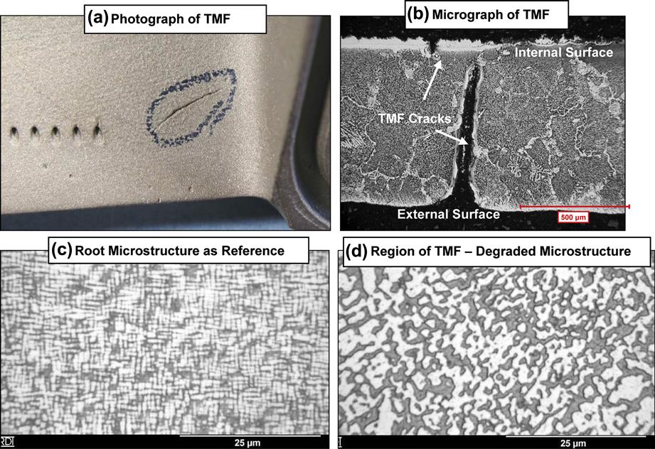
The overall base metal degradation was considered more advanced than typical for blades of similar service hours. The region of TMF damage exhibited significant base alloy degradation indicating this area had a relatively high operating temperature. This elevated operating temperature would have (a) resulted in large thermal changes during engine starts/stop and (b) have reduced the material strength. Both factors would have contributed to thermal cracking.
Without destructive testing and the detection of the internal TMF cracking, a repair shop could run the risk of basing reparability upon external features alone. In this example, only a portion of the blades exhibited external cracking. However, because internal TMF cracking was detected, the entirety of the blade set was recommended for retirement. Also, the engine operator was made aware that the advanced degree of base metal degradation indicated the engine had been over-firing, which had increased the blades' susceptibility to TMF.
Case Study 10: Evolution of IGT “F” Class Repair Technology22
Starting with OEM replacement philosophy based on theoretical design calculations, the gas turbine industry has evolved to a condition-based criteria for repair and life extension of expensive critical hardware. By using proper metallurgical and mechanical analyses and design criteria, it is possible to develop safe repairs capable of maximizing the life of the blades and vanes. However, significant differences exist in the execution, technology and standards used by various repair facilities, which have resulted in confusion and discrepancies in the ultimate life and reliability of repairs. The need for some form of industry standard is clearly evident, especially for “F” class component repairs, where safety margins are low and technology requirements are high. Experience has demonstrated that excellent results can be obtained in a variety of “F” class components, which should reduce the dependence on expensive long-term service agreements.
In hindsight, looking at practices employed in the 1960s and 1970s to assess the life and replacement of hot section components from such engines as the W101, W191, Frame 3, and Frame 5, we can see how conservative the OEM’s were and the resultant waste in replacement parts. The basic method used by the OEMs was to destructively test sample blades at their overhaul interval and reject anything that did not meet the new material specification. Often, blades were scrapped because the stress rupture elongation fell below the specified 5% minimum and designers did not know the implications of operating with a lower arbitrary value. Most components were automatically replaced when they reached their theoretical creep life limit, which ranged from 40,000–100,000 hours on the turbines operating at 760°C (1450°F). Subsequently, these same components were rejuvenated and obtained lives in excess of 200,000 hours.
Some of the operators and OEM engineers started to question the need for automatic component replacement in the early 1970s and started to develop improved analytical techniques for examining micro-structural aging and heat treatment reactions that led to development of the rejuvenation process at Westinghouse Canada. The first paper coining the term “rejuvenation” to describe the successful reheat treatment of super alloys was presented in 1977 by Westinghouse. However, it was Chromalloy that led to the commercialization by repairing Frame 5 second stage buckets with a creep life limit.
Most of the repair processes used at the start were adapted from aero repairs from such engines as the P&W JT8D, which were conservative in nature and regulated by the FAA. Since no such restrictions were present in the industrial market, every new entrant tried to imitate, as well as push, the repair limits to try to recover more parts. Ultimately this led to varying standards for the same part repair and in some cases in failures.
The problems with the IGT market were aggravated in the 1990s with the entry of several new players and spin-off companies in the Houston area, lured by the growing installed base and flawed predictions as to their overhaul requirements. This coincided with the introduction of the “F” class turbines with their higher firing temperature and more sophisticated component designs. Operators concerned with the level of technology available in the aftermarket and the maintainability of their units sought refuge in OEM long-term service agreements.
Following the ENRON correction, there was a significant drop in demand for repair services and companies started to compete more on price than technology. In some cases, repairs have become a commodity item, with little regard to technical subtleties and long-term life. Caution must be exercised when applying relaxed standards to advanced components since it can lead to failures.
The best value is obtained by applying the appropriate level of understanding and technology to obtain a repair that provides the ultimate life for the asset in question. For example, a Frame 7 EA first stage bucket can be repaired by several methods that all appear to be alike, but may be different in significant aspects relating to how well the microstructure and the coatings are restored to a “like new” condition. For example, by following conventional practices that simplify the processing by not stripping the internals and by not doing a full high temperature solution treatment, the ultimate life of the bucket is limited to about 48,000 hours. However, by engineering a complete rejuvenation of the structure and coatings, the life for the same component can be extended to over 100,000 hours with resultant savings in overall replacement cost estimated in the millions.
For the “F” class components, the question of value and repair technology is even more important. By using advanced welding, powder metallurgy, coating, and rejuvenation techniques, it is possible to extend the life of these expensive components and lower the operating costs to levels significantly lower than LTS Agreement levels. This can be best illustrated by the examples of successful repairs that combine advanced aero experience with the knowledge of IGT design and metallurgical processes.
Technology
The high firing temperatures in F technology engines are achieved by the combination of several different material and design technologies. While the resulting performance improvement is a quantum increase over previous engines, the technologies themselves have mostly been adapted from those that were in use in older industrial and aeroengines. From a repair perspective, this means that the techniques used in repair of F class hardware have mostly been used previously on either industrial or aero hardware.
Features of F Class Hardware
Advanced Coatings
The F class of engines makes more extensive use of coatings than previous generations of engines:
• F technology engines are the first industrial designs to use thermal barrier coatings (TBCs) on rotating airfoils. Previously, the use of TBC coatings in industrial designs was restricted to stator vanes and combustion hardware applied by air plasma spraying. To meet the demands of coating the more critical rotating blades, advanced techniques such as electron beam evaporation and high energy plasma spraying whose use had been restricted to aero components in the past are now used to generate more strain tolerant coatings (Figure 12–33).
• Coatings are applied to downstream stages that were uncoated in earlier designs. The coatings are the same type of MCrAlY coatings that were used in the first stages of previous engines.
• Internal coatings play a more critical role. The thin walls associated with the complex serpentine cooling passages result in higher surface temperatures on the cooling hole walls and therefore need protection against oxidation. The coating processes, however, are the same processes used in earlier industrial and aero designs.
Single Crystal and DS Materials
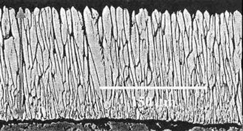
The first use of single crystal alloys in industrial gas turbines is found in F technology engines (Figure 12–34). While such alloys have been used for many years in aero-engines, the challenge of casting larger industrial components prevented their use in industrial engines until recently. The F technology engines also see much more extensive use of directionally solidified alloys, which saw use only in the first stage blades of some of the previous generation of industrial engines.
Complex Geometry
The geometry of components used in the current generation of industrial engines is more complex than in previous generations. The schemes used to cool the airfoils feature serpentine passages and surface film cooling holes similar to those used previously in aircraft parts. Also, the geometry of combustor hardware has increased in complexity due to the demands of increased cooling and lean premixed combustion to achieve low emissions at higher turbine inlet temperatures.
Repair Technologies
Stripping
Since coatings were first introduced to protect turbine airfoils, stripping has played a central role in repair processing. First, coatings are often largely consumed by environmental attack in service. Chemical stripping is the first step towards replacing the spent coating. Second, for most coated airfoils, it is essential that the coating be removed prior to any solution heat treatment in order to prevent excessive diffusion and rumpling of the surface. The acid solutions used to dissolve the aluminum-rich phases in the coating are very aggressive. To prevent intergranular attack of the base material or dissolution of Ni3Al (γ′) eutectic islands in some of the newer high strength superalloys, the temperature and compositions of solutions and immersion times must be carefully controlled.
The ability to strip coating from internal passages is a requirement for both F technology components and earlier generation hardware. However, because of the higher temperatures at which the F components operate, coating removal is necessary to replace exhausted internal coatings, whereas in earlier hardware, it was typically necessary to allow full rejuvenation heat treatment. To accomplish this, a modern chemical stripping process must be able to flow the hot solution in a controlled manner through the internal cooling passages, in order to remove any internal coatings, while simultaneously stripping the thicker external coatings. Special care must be taken to prevent chemical attack on the critical blade root surfaces and inside internal cavities. An experienced technical staff is required to safely operate and maintain such advanced stripping facilities.
A new stripping need has developed in the F engines due to the higher temperatures in the cooling passages. At these temperatures, thick layers of oxides can form during service. These oxides are not dissolved by the solutions used to remove coatings and act as a barrier to both coating stripping processes and re-coating operations. On the external surfaces, this is not a problem, since the oxides can be removed by abrasive cleaning (grit blasting). However, on the internal surfaces a chemical approach must be used.
Advanced cleaning techniques are now being qualified to clean the internals and provide superior coating protection for the internal cavities.
Rejuvenation
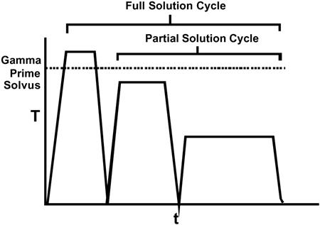
Vacuum heat treatments are traditionally used during the repair process to restore the microstructure, improve weldability, apply brazes and diffuse coatings. Significant metallurgical knowledge and experience are required to tailor the heat treatment steps to the superalloy being processed. To ensure that the creep, fatigue, and aging damage incurred during service are reversed as much as possible, and that the correct microstructure and mechanical properties are produced after all welding and coating steps have been completed, a full solution heat treatment, graphically illustrated in Figure 12–35, is essential.
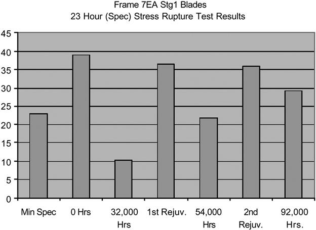
The benefits of regularly performing such rejuvenation in combination of other repair steps have been well established on earlier generation engines. By restoring the microstructure through heat treatment on a routine basis, the life of the components can be extended well beyond the life at which they would otherwise need to be retired (Figure 12–36). For example, the use of rejuvenation at appropriate intervals for Frame 7EA first and second stage buckets can extend their life to more than twice that achievable through re-coating only (Figure 12–37). The economic benefit at a site operating four units was calculated to be approximately $5 million over a 5-year period.
DS and Single Crystal Alloys
The same principle of extending the life of hot section components by rejuvenation heat treatments has been applied to directionally solidified components as they have been introduced in the earlier industrial and aero engines. The heat treatments function in the same way to restore the gamma prime microstructure and related mechanical properties.
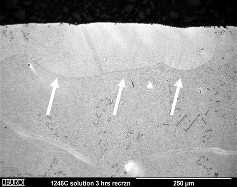
An additional concern for DS and single crystal alloys is the possibility that recrystallization will take place during heat treatment if the components have been subject to plastic deformation. These alloys develop their strength in part from controlling the orientation of grain boundaries or, in the case of single crystals, eliminating them all together. Figure 12–38 shows recrystallization of a single crystal alloy subjected to shot peening to introduce surface deformation. If such damage were to occur on an airfoil surface, for example, as a result of impact, the LCF and creep properties would be reduced. Rejuvenation of DS and single crystal alloys must therefore include examination of the etched airfoil surfaces for evidence of recrystallization after the heat treatments.
Repair Materials
Welding
Many repairs involve the replacement of missing material or repair of cracking. Welding is the most common method used to repair, join, or replace material in hot section components. The conventional means of depositing material is by fusion welding, which has been used for repair of airfoils since the 1970s. The process can vary from manual TIG to automated plasma- or laser-based systems with the best results obtained from tightly controlled integrated equipment.
With the more readily weldable alloys used in combustors and stator vanes, extensive weld repair of these components is possible, although distortion can become a problem. However, with the higher strength alloys used for rotating blades, the tendency of the base metals to crack is a serious limitation. For this reason, repairs are typically limited to the low stressed regions at the tip of the blades. Furthermore, in more recent engines, including the F class engines, oxidation resistance has also become an important issue.
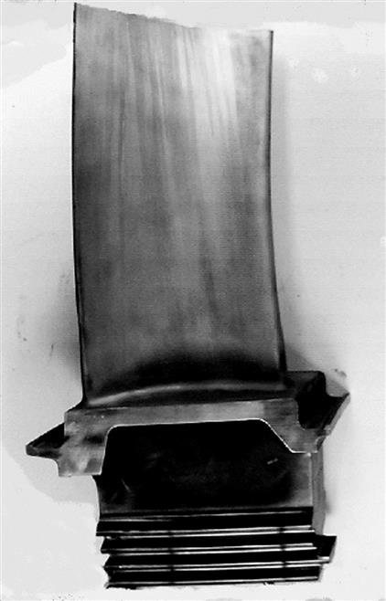
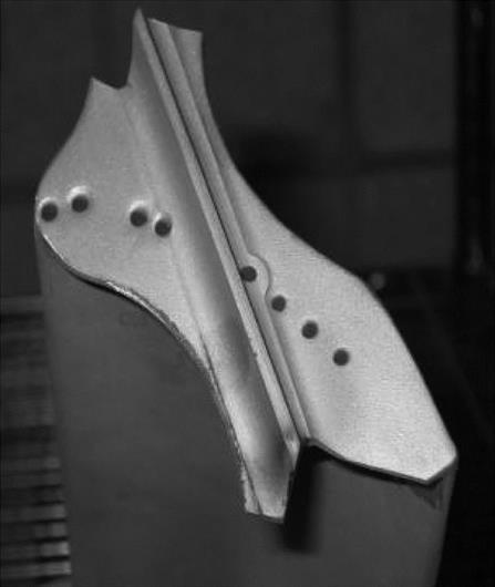
The experience with the RB211 HP blades shown in Figure 12–39 represent a good example of how the use of superior welding and materials technology can be used to produce a longer life repair, by harnessing the use of higher oxidization resistant materials that are extremely difficult to weld. The same processes were subsequently applied to successfully restore the tips on the Frame 7FA and V84.3A blades discussed below.
Selection of weld filler materials is a balance of the properties required in the joint and the weldability needed. Ideally, welds would be performed with filler metal compositions matching those of the base material, which typically have strengths approaching those of the cast alloy. This can typically be achieved with the cobalt alloys used in many stator components and weaker nickel alloys used in combustors, because the alloys are fairly readily weldable. However, for higher strength nickel-based alloys used for rotating blades, weldability becomes a serious problem and most repairs are performed with weaker alloys, such as Inconel 625, that have good weldability. By limiting repairs to low stressed regions, this approach has been used to successfully extend the life of older generation blades.
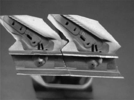
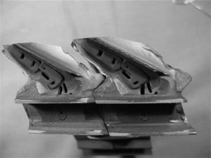
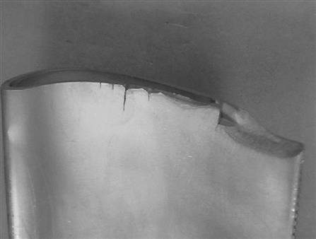
In the 1990s, as firing temperatures increased, first in aeroengines and then in the F class engines, oxidation began to become a factor in weld alloy selection. The lower strength alloys used for conventional repair have lower aluminum content and are therefore less oxidation resistant. For example, new Rolls Royce RB211-24C high-pressure turbine blades (Figure 12–39) typically lose material from the shroud edges by oxidation after one overhaul cycle (24,000 hours), necessitating weld repair. However, experience with conventional weld repairs showed that the repaired shroud edges oxidized at an accelerated rate, resulting in their removal from service for further repair after 8000 hours (Figure 12–40).
To select an appropriate weld filler material for such oxidation limited applications, candidate alloys with higher aluminum content were compared to the base material and conventional repair materials by cyclic oxidation testing. The higher aluminum alloys have significantly better oxidation resistance. However, the weldability of these alloys is significantly less than the conventional materials and cannot be reliably applied by manual welding because of cracking problems.
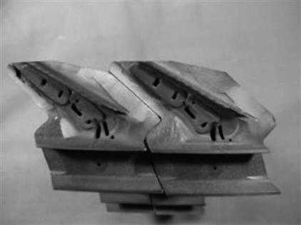
It has been shown that automating welding processes for superalloys reduces their tendency to crack. The automated techniques were therefore developed for repairs with these oxidation resistant fillers. This approach was used to repair the RB211-24C high-pressure blades, with the result that the repaired blades last to the 24,000 overhaul interval in better condition than new hardware (Figure 12–41).
LPM™ Powder Metallurgy
In many cases, welding is not desirable because of excessive distortion or cracking considerations. For this reason, there has been considerable effort in developing non-fusion weld repair techniques. Over the past two decades, many wide gap and modified wide gap processes have been developed and employed in the repair and manufacture of hot section gas turbine components; G.E.’s advanced diffusion healing (ADH), Snecma’s rechargement per brasage diffusion (RBD), Howmet’s effective structural repair (ESR), Chromalloy’s surface reaction braze (SRB), Turbofix, Sermafill, and Liburdi Engineering’s LPM™. All of these processes use high and low melting components to limit the amount of melting point depressant and to help bridge large gaps. However, the patented LPM™ process is the only modified wide gap process capable of filling large cavities resulting from the removal of structural cracks or casting core holes. In particular, the LPM™ process has been used to rebuild components that are missing large amounts of material while maintaining very low levels of melting point depressants.
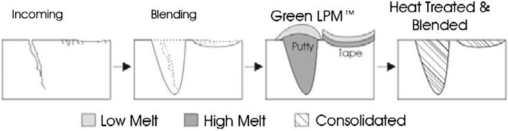
The LPM™ process is a multi-layer process incorporating high and low melting metal powders to effect sintering and controlled liquid phase bonding. The powders are mixed with organic binders to produce flexible tapes or clay-like putties. The component is then heated slowly in a vacuum furnace to burn off the binders and finally heated to and held at a temperature between the melting points of the high and low melt materials to promote liquid phase sintering, transient liquid phase solidification (isothermal solidification) and diffusion bonding (Figure 12–42). The resulting deposits show excellent mechanical strength, creep strength, and ductility when compared to conventional wide gap deposits, without the need for lengthy diffusion cycles.
Because of its ability to bridge such wide gaps, the LPM™ process can be used to repair very large, structural cracks as well as to build up material on worn surfaces for dimensional or throat area restoration. Since the liquid phase consolidation takes place while the part is at a uniform temperature in the vacuum furnace, there is no lateral shrinkage or distortion. Since its introduction in the early 1990s, the process has been used to repair and upgrade numerous hot section vanes, blades, combustors and transitions.
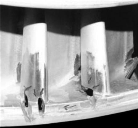
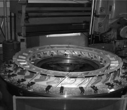
Experience with the repair of the frame 7EA nozzles demonstrates the effectiveness of the LPM™ process. After an initial 24,000-hour service interval since new, these FSX 414 cobalt alloy nozzles typically show extensive cracking especially around the leading edges, trailing edges and between the two airfoils on the outer shroud. The cracking is primarily caused by low cycle thermomechanical fatigue. The cracking at the leading edges is branched and extended through to the internal vane cavities. Some oxidation erosion and associated cracking also occurs on the outer and inner diameter shrouds between the airfoils. Because of the degree of damage, conventional weld repairs would either crack or result in excessive distortion of the nozzles.
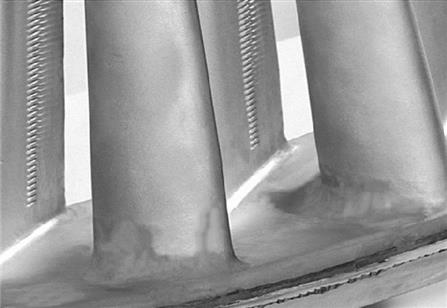
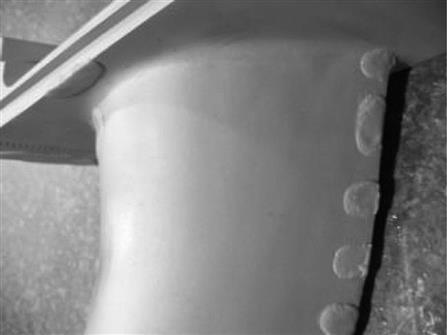
In preparation for LPM™, the cracks are ground out and the eroded surfaces are blended back to unaffected base alloy. This leaves large holes ranging from 25 mm × 100 mm in size at the leading edges of some airfoils to areas larger than 50 mm × 50 mm requiring 0.75 mm build-ups (Figure 12–43). The large holes, which are typical of vane repairs where the structural cracks are removed, were filled with LPM™ putty that was sculpted to the original contour of the nozzle. The eroded areas were covered with a 1 mm thick LPM™ tape to restore the dimensions. Small cracks and impact damage were repaired with the LPM™ putty (Figure 12–44). During repair these areas were successfully repaired using MarM247-7 LPM™.
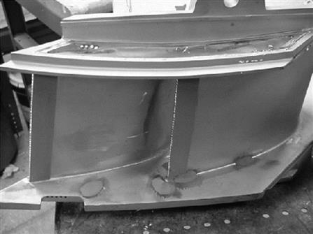
After the second service interval of approximately 24,000 hours (∼48,000 hours total operating time), the nozzles do not show the large thermomechanical fatigue cracks at the leading edges or between airfoils on the outer shroud surface formed in the new parts. This suggests that the LPM™ had improved the performance of these nozzles due to the improved strength and low cycle fatigue resistance of the LPM™ repair (Figure 12–45).
After 48,000 hours of service, the nozzles had small cracks on the shrouds, oxidation erosion on the internal and external surfaces, and thinned trailing edges. The thinned trailing edges were particularly of concern as the throat area between the airfoils had increased significantly due to material loss during service and repair. This increase in throat area can lead to harmonic imbalance and efficiency loss. As part of the second repair the small cracks and oxidation damage were blended in preparation for LPM™ application and the thinned trailing edges and oxidized areas were thickened by applying LPM™ tape to both surfaces. The cracks were repaired using LPM™ putty. After the second repair the nozzles were again returned to service. The nozzles have since been returned for an LPM™ repair at ∼72,000 hours. After repair, the nozzles will be returned for an additional service interval.
Coatings
Coatings are an integral part of any repair process. In principle, the application of coating during repair is no different than during the original manufacture. However, the overhaul cycle presents an excellent opportunity to review how well the original manufacturer’s coating is performing and substitute a more appropriate coating where possible or apply coating to previously uncoated surfaces. For example, the original GT 29 coating applied to the frame 7EA first stage buckets had poor oxidation resistance, while the replacement GT 29 plus coating was too brittle and cracked in service. The repair of these buckets involved the application of a more ductile and oxidation resistant over-aluminized NiCoCrAlY by GE.
A properly engineered repair will specify a proven-McrAIY coating appropriate to the engine operating environment, followed by an internal and external aluminide coating. Where needed, a thermal barrier coating is applied over the MCrAIY layer to provide an added level of insulation.
F Class Repairs
Just as the technology used in the manufacture of the F class components evolved from those used in the previous generation of turbines, the repair of these components use the same technologies that have been developed and proven over the last 20 years. The typical repair workscope still involves the following basic steps; incoming inspection, removal of coatings, repair of missing material by welding or LPM™, rejuvenation heat treatment, and application of appropriate coatings. However, as in all repair applications, it is essential that the damaged mechanisms are well understood so that appropriate repair techniques and materials are chosen.
The following examples illustrate the application of repair to the latest generation of turbine hardware.
GE Frame 7F
First Stage Buckets
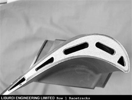
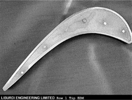
The first stage buckets in the GE frame 7F engine are manufactured from directionally solidified GTD 1 1 1 alloy. They feature a complex serpentine cooling scheme and are coated with an over-aluminized NiCoCrAIY coating on the external surfaces and a simple aluminide coating on the internal passages. The most typical damage requiring repair is oxidation and cracking of the tip (Figure 12–46) and general consumption of the coating life.
The repair workscope typically involves the following steps:
• Strip coatings (internal and external)
• Fluorescent penetrant inspection
• Tip weld repair with oxidation resistant filler (Figure 12–47)
Second Stage Buckets
The second stage buckets on the frame 7F suffer from a similar problem as the 7EA buckets. In both engines, the shrouds lift due to the centrifugal forces acting on them, resulting in misalignment of the Z notch contact faces. The repair developed for this type of damage involves applying material by the LPM™ process to realign the contact faces and restoring the contacts surfaces by hard face welding (Figure 12–48). During this repair, it is possible to realign the shroud to lower the stresses and reduce the tendency for future shroud lift.
The typical workscope for repair of these buckets would include:
Nozzles
While the geometry of the nozzles in the frame 7F turbine are different than those in the EA model, the materials and construction and general features are very similar. The repair of these components, therefore, is similar to that described for the 7EA components described above. The differences in geometry, of course, require different tooling (Figure 12–49).
Combustors
Since the materials used in the manufacture of combustors are readily weldable, repairs are typically based on welding cracks and missing material. However, there are many applications where distortion may be an issue, such as when surfaces need to be built up over a large area, and in these instances, the LPM™ technique is more suitable. The principal difference between the F class combustors and earlier models is the increasing complexity in geometry. For this reason, having appropriate gauging and tooling is increasingly important (Figure 12–50).
Siemens V.84.3
Rotor Blades
The first two stages of rotating blades in the Siemens V.84.3 are manufactured from a single crystal alloy PWA 1483 and are coated with an MCrAlY coating on the external services and an aluminide on the internal surfaces. The remaining rows of blades are made from conventional cast alloys. All of the blades are of an unshrouded design, with the first stages employing a serpentine cooling scheme.
The rotor blades in the Siemens V.84.3 exhibit many of the same types of damage observed in the GE frame 7F first stage buckets, including tip cracking and oxidation. In addition, these blades suffer from short cracks along the trail edges. The repairs therefore are very similar in scope to those employed on the 7F buckets. Because of their location, the cracking the along the trailing edges can only be repaired by blending away the damaged material.
The repair workscope for the Siemens V 84.3 rotor blades involves the following steps:
Stator Vanes
The stator vanes in the V.84.3 design differ from those in the GE design in several ways. In addition to the obvious geometry differences, these vanes are manufactured from high strength nickel-based superalloys used only for rotating components in GE designs.
From our repair perspective, this means that repair by welding techniques will not be practicable. While welding is possible, the tendency for cracking to occur within the base material will limit the yield achievable by a welding process. By contrast, the LPM™ process avoids the stresses associated with the welding process making full yield repairs possible. Figure 12–51 shows trailing edge cracking in a V.84.3 second stage vane during the LPM repair process.
The typical workscope for repair of V.84.3 stator airfoils includes:
Alstom 11N2
Rotor and Stator Airfoils
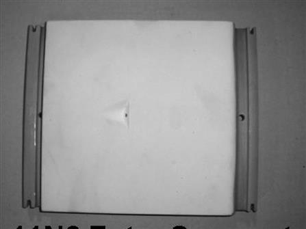
The Alstom 11N2 has a lower firing temperature than either the GE or Siemens design and does not employ single crystal or directionally solidified materials in the hot section. Nonetheless, it employs the same coating systems, namely MCrAlY coatings on rotating blades and thermal barrier coatings on the stationary airfoils. It is also subject to the same types of degradation and the repairs are therefore similar in scope.
The repair of the first stage blades from these engines is a good example of using repair as an opportunity to improve the components. Unlike the Siemens and GE hardware, the first stage blades as originally supplied by Alstom do not have a coating on the internal cooling passages. As a consequence, significant oxidation typically occurs during service. Ideally, it would be beneficial to provide an internal coating at repair to extend the life of the component. However, the oxide layer acts as a barrier to the formation of the aluminide coating.
To remove the oxide layer, a unique stripping process was developed. The process effectively removes the oxide layer so that aluminum can come in contact with the substrate to form an aluminide coating during the slurry coating process. This aluminide layer will prevent oxidation from becoming a life-limiting factor in continued operation and thus will extend the total life of the blades.
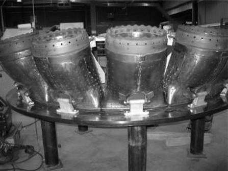
Combustor Hardware
Because the combustor in the 11N2 engine is of a silo type, the components appear to have little similarity to those in a GE engine (Figure 12–52). However, in both instances, the components are manufactured from readily weldable materials, so the repair workscope is actually very similar. The components typically suffer from wear and cracking, which can be repaired by welding. Surfaces that are protected by a thermal barrier coating will have the coating removed and reapplied as part of the repair process.
Conclusions
The F class of engines operates at significantly higher firing temperatures than previous generations. To achieve this they use a combination of advanced materials, coatings, and component design features. However, the earlier industrial gas turbine designs incorporated many of these features individually and significant experience had also been accumulated in aeroengines. For this reason, the designs can be seen as evolutionary rather than revolutionary.
By the same token, the development of repairs for the F class of engines has been an evolutionary process. The techniques used to repair the previous generation of components have largely been applicable to the F components. By employing these techniques, it is possible not only to economically extend the life of the components, but, in some instances, to improve the components through the use of more oxidation resistant materials and coatings.
Case Study 11: Liburdi Powder Metallurgy, Applications for Manufacture and Repair of Gas Turbine Components23
The Liburdi Powder Metallurgy (LPM™) joining process has been improved through the addition of new superalloy compositions and the development of hard particle-based compositions. Two new compositions based on MarM247 have been developed, tested and applied to hot section gas turbine components. These new compositions show improved microstructures and excellent mechanical properties. In addition to the conventional superalloy LPM™ materials, a hard facing LPM™ material based on wear resistant and abrading compositions incorporating hard particles in an oxidation resistant matrix have also been developed. This section discusses the mechanical and physical properties of the different materials developed and presents examples of different applications for these materials.
Over the past two decades many wide gap and modified wide gap processes have been developed and employed in the repair and manufacture of hot section gas turbine components; GE’s Advanced diffusion healing ADH, Snecma’s rechargement per brasage diffusion RBD, Howmet’s effective structural repair ESR, Chromalloy’s surface reaction braze SRB, Turbofix, Sermafill, and Liburdi Engineering’s LPM™. All of these processes involve the use of high and low melting components to help limit the amount of melting point depressant and to help bridge large gaps. The patented LPM™ process is the only modified wide gap process capable of filling large cavities resulting from the removal of structural cracks or casting core holes. In particular the LPM™ process has been used to rebuild components that are missing large amounts of material while maintaining very low levels of melting point depressants. Additionally, the LPM™ process has been extended to applying abrading and wear resistant materials to change the surface properties of hot section components.
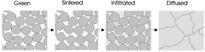
The patented LPM™ process is a multi-layer process incorporating high and low melting metal powders to effect sintering and controlled liquid phase bonding. The powders are mixed with organic binders to produce flexible tapes or clay like putties. During application of the tape or putty to the new component or repair area: the area is prepared for LPM™, the low melt material is applied on top of the high melting material, and the ratio of the two materials is carefully controlled (Figure 12–53). The component is then heated slowly in a vacuum furnace to burn off the organic binders and finally heated to and held at a temperature between the melting points of the high and low melt materials. During the heating process the high melting point material sinters to form a rigid structure. Once the melting point of the low melting material is exceeded the rigid structure is infiltrated by the low melting material at which point liquid phase sintering, transient liquid phase solidification (isothermal solidification) and diffusion bonding occur. The resulting deposits show excellent mechanical strength, creep strength, and ductility when compared to conventional wide gap deposits without the need for lengthy diffusion cycles.
The major advantage of using the LPM™ process is that it does not result in the distortion or cracking commonly associated with welding. This allows for large surface restorations that would otherwise distort or crack the component beyond repairable limits. It also makes it possible to repair cast superalloys components that would crack beyond acceptable limits during welding.
LPM™ has been used in the repair of nozzles, vanes, blades, and buckets from GE Frame 3, 5, 6B, 7B, 7E, 7EA, 7FA, LM1600 and LM2500, Siemens Westinghouse W191, W251 B8, B10, B12, and W501D5, Rolls Royce T56, RB211, Avon and Spey, Alstom Tornado and TB5400, Dresser Rand DJ270, and others. LPM has also been used in the new manufacture of W501G Row 1 and Row 2 blades and some Solar turbine blades. LPM™ has proven an effective tool in the manufacture and repair of hot section turbine components. The following sections discuss the properties of the newer MarM247-based, abrading, and wear resistant LPM™ compositions and present some typical LPM uses.
Superalloy LPM™
The initial LPM™ composition developed was based on IN738. This composition showed good properties but it was felt that improved properties could be developed using other alloys. A matrix of various high and low melt components was developed and various alloy combinations were evaluated for suitability in the LPM™ process. Both cobalt and nickel-based compositions were evaluated. The results showed that compositions based on MarM247 had a very desirable microstructure. Two new MarM247 based compositions were further tested and evaluated MarM247-3 and MarM247-7.
Microstructure
The microstructure of the original IN738 LPM™ material contained elongated borides. The 100 μm to 500 μm borides were inter-granular and had length to width ratios of greater than 10:1. This microstructure resulted in lower ductility but tended to perform well in service.
Both of the newer MarM247 LPM™ compositions have small cuboidal boride particles. The 10 μm to 50 μm cuboidal particles are found intra-granularly and have a length to width ratio of about 1:1. As a result, these two new compositions show improved ductility and better fracture properties than the IN738 LPM™ material. The MarM247-7 composition has a slightly higher volume fraction of borides than the MarM247-3 but both have lower boride volume fractions than the IN738-based material. The borides in the MarM274-3 structure tend to be smaller than those in the MarM247-7 structure.
All LPM™ compositions show a good interface with the base alloy. LPM™ materials have been applied to the following alloy systems: GTD111, GTD222, Rene N4, IN738, IN939, IN625, MarM002, MarM247, Rene 80, Rene 125, Rene 142, Hastelloy X, CMSX 4, C1023, U500, U520, U700, U720, 304 stainless steel, 321 stainless steel, 347 stainless steel, ECY768, X40, X45, FSX414 and others. No needle-like topologically close packed phases (TCP), microcracks, or abnormal phases were found at the interface between LPM™ and any of the aforementioned alloys. The interface between LPM™ is generally a 50 μm interdiffusion zone that contains a coherent interface with the base alloy.
Microscopic examinations of large cross-sections of the original IN738 LPM™ and the newer MarM247-based compositions have shown that any pores tend to be smaller than 125 μm in size and total porosity levels are lower than 1%. As the LPM™ material is produced from fine powders, the resulting microstructure has a very fine grain size.
Composition
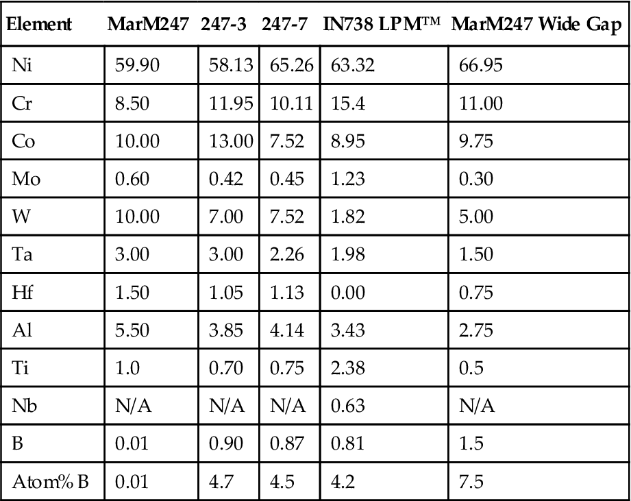
Due to the multi-layer nature of the LPM™ process the resulting deposits have a very low weight percent of boron, the melting point depressant used in the low melt component (Table 12–4). As boron is a very light element having an atomic mass of 11 compared to 59 for nickel, small weight percent changes in boron result in very large changes in the atom percentages. Most conventional wide gap processes contain 1.5 weight percent boron or more. The LPM™ materials contain less than 0.9 weight percent boron due to the deposits containing less than 30% low melting material. The small weight percent and subsequent atomic percent of boron in the LPM™ materials leads to low volume fractions of boride and better ductility than other brazing processes. The less than 30% low melting material also results in high levels of γ′ forming elements and subsequently excellent creep properties as is evident in the relatively large amounts of Al and Ti in the LPM™ material when compared to conventional wide gap materials.
TABLE 12–4
Chart Showing the Compositions of the Various LPM™ Materials, a Typical 50:50 MarM247 Wide Gap Material, and the Nominal Composition of MarM247
| Element | MarM247 | 247-3 | 247-7 | IN738 LPM™ | MarM247 Wide Gap |
| Ni | 59.90 | 58.13 | 65.26 | 63.32 | 66.95 |
| Cr | 8.50 | 11.95 | 10.11 | 15.4 | 11.00 |
| Co | 10.00 | 13.00 | 7.52 | 8.95 | 9.75 |
| Mo | 0.60 | 0.42 | 0.45 | 1.23 | 0.30 |
| W | 10.00 | 7.00 | 7.52 | 1.82 | 5.00 |
| Ta | 3.00 | 3.00 | 2.26 | 1.98 | 1.50 |
| Hf | 1.50 | 1.05 | 1.13 | 0.00 | 0.75 |
| Al | 5.50 | 3.85 | 4.14 | 3.43 | 2.75 |
| Ti | 1.0 | 0.70 | 0.75 | 2.38 | 0.5 |
| Nb | N/A | N/A | N/A | 0.63 | N/A |
| B | 0.01 | 0.90 | 0.87 | 0.81 | 1.5 |
| Atom% B | 0.01 | 4.7 | 4.5 | 4.2 | 7.5 |
(Source: Liburdi Engineering.)
Test Bar Manufacture
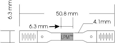
Most of the studies done on conventional and modified wide gap processes have concentrated on joint widths not larger than about 1.5 mm. These small joints widths allow for large amounts of boron to diffuse out of the joint into the base material. Often the joints are given long diffusion cycles of up to 24 hours to allow for the diffusion of the boron into the base alloy. Thus the data generated from these test bars is not representative of the mechanical properties of overlays or relatively thick repair joints formed on actual component repairs. It was felt that for this testing the butt joint should be 6.3 mm wide such that diffusion into the base alloy did not play a role in the joint properties at the centerline of the joint. The test bars with a 6.3 mm joint width should be representative of the bulk LPM™ properties and should also test the interfacial strength.
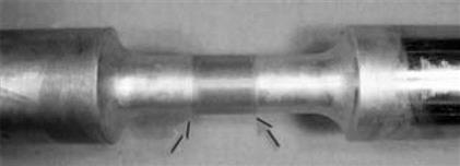
6.3 mm × 6.3 mm slots were cut down the center of several 50.8 m × 50.8 mm × 9.5 mm MarM247 blocks. These slots were filled with the MarM247 LPM™ materials and heat treated for not more than 2 hours at the maximum temperature reached during the alloy solution cycle. The blocks were then aged for 2 hours at 1120°C and 16 hours at 843°C to produce the desired γ′ precipitate structure. Stress rupture and tensile bars were cut from the blocks such that a 6.3 mm region in the center of the gauge was LPM™ (Figures 12–54 and 12–55). The bars were X-ray and fluorescent penetrant inspected. Test bars with defects larger than 500 μm were rejected.
Tensile Properties
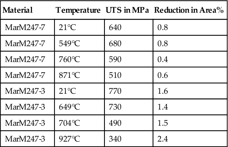
Tensile test bars were tested at a variety of temperatures. Table 12–5 shows the ultimate tensile strength and reduction in area for each of the test bars. The MarM247-3 material shows slightly better ductility due to the small boride particles and the smaller volume percent of borides. The ductility of the MarM247 based LPM™ materials is only slightly lower than that for common nickel-based superalloys and is considerably higher than the levels for conventional wide gap brazing processes that generally show little or no ductility. None of the bars failed at the interface and all bars failed intergranularly as would be expected. The modulus for both materials was approximately 170 GPa.
TABLE 12–5
Tensile Properties of the MarM247-3 and MarM247-7 LPM™ Materials
| Material | Temperature | UTS in MPa | Reduction in Area% |
| MarM247-7 | 21°C | 640 | 0.8 |
| MarM247-7 | 549°C | 680 | 0.8 |
| MarM247-7 | 760°C | 590 | 0.4 |
| MarM247-7 | 871°C | 510 | 0.6 |
| MarM247-3 | 21°C | 770 | 1.6 |
| MarM247-3 | 649°C | 730 | 1.4 |
| MarM247-3 | 704°C | 490 | 1.5 |
| MarM247-3 | 927°C | 340 | 2.4 |
(Source: Liburdi Engineering.)
Creep Properties
Stress rupture tests were performed using the bars described previously. The tests were conducted to ASTM E139. The stress time and temperature were varied to generate a broad range of Larson Miller parameter values. The temperature varied from 787–982°C and the stress varied from 5–35 MPa. The Larson Miller plot is shown in Figure 12–56. The average reduction in area was 4.2% for the MarM247-7 LPM™ and 7.3% for the MarM247-3 LPM™. These values are similar to those for cast MarM247.
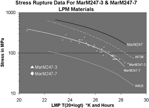
Due to the fine-grained nature of LPM™ materials, they tend to have lower creep strengths when compared to large grained cast nickel-based superalloys. The LPM™ materials have creep strengths higher than conventional welding alloys such as IN625 for nickel-based superalloys and L605 for cobalt-based superalloys.
The creep strength compares more closely to fine grained wrought superalloys and cobalt-based superalloys. During the studies it was also found that the creep properties of LPM™ varied little with the composition. It has been hypothesized that the creep properties are highly dependent on the grain size. Studies to this effect will be conducted in the future by increasing the grain size through long diffusion cycles.
Low Cycle Fatigue
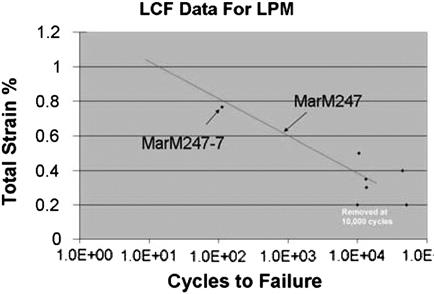
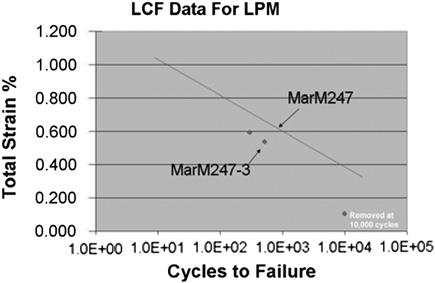
Low cycle fatigue test bars were produced as described previously and were inspected for surface defects larger than 0.50 mm. The testing was conducted at 850°C using a trapezoidal waveform at an R ratio of –1.0. The specimens were held at the maximum compressive strain for 2 minutes during each cycle. Failure was defined as the point at which the maximum stress amplitude decreased to 50% of the value at 100 cycles. It should be noted that the butt joint in the middle of the test bars produces an effective gauge length of only 6.3 mm and the strain is measured over the total gauge length. During testing the majority of the elongation occurs in the 6.3 mm joint. This means the strain in the joint area is much higher than that measured. The data reported in Figures 12–57 and 12–58 are for the total strain over the gauge length of the test bar. Testing indicated the fatigue properties are similar to that of cast MarM247 for MarM247-7 and likely slightly lower properties for the MarM247-3.
Superalloy LPM™ Example #1: General Electric MS7001EA Row 1 Nozzles
After the initial 24,000 hour service interval, these FSX 414 cobalt alloy nozzles show extensive cracking especially around the leading edges, trailing edges, and between the two airfoils on the outer shroud. The cracking was primarily caused by low cycle thermomechanical fatigue. The cracking at the leading edges was branched and extended through to the internal vane cavities. Some oxidation erosion and associated cracking had also occurred on the outer and inner diameter shrouds between the airfoils. Based on the degree of damage it was felt that conventional weld repairs would either crack or result in excessive distortion of the nozzles. It was decided the LPM™ was the best approach for repair.
In preparation for LPM™ the cracks were ground out and the eroded surfaces were blended back to unaffected base alloy. This left large holes approximately 25 mm × 100 mm in size at the leading edges of the airfoils of several nozzles and areas larger than 50 mm × 50 mm requiring 0.75 mm build-ups (Figure 12–59). The large holes, which are typical of vane repairs where the structural cracks are removed, were filled with LPM™ putty that was sculpted to the original contour of the nozzle. The eroded areas were covered with a 1 mm thick LPM™ tape to restore the dimensions. Small cracks and impact damage were repaired with the LPM™ putty. During repair these areas were successfully repaired using MarM247-7 LPM™.
After the second service interval of approximately 24,000 hours (∼48,000 hours total operating time), the nozzles did not show the large thermomechanical fatigue cracks at the leading edges or between airfoils on the outer shroud surface. This suggested the LPM™ had improved the performance of these nozzles due to the improved strength and low cycle fatigue resistance of the LPM™ repair (Figure 12–60).
After 48,000 hours of service, the nozzles had small cracks on the shrouds, oxidation erosion on the internal and external surfaces and thinned trailing edges. The thinned trailing edges were particularly of concern as the throat area between the airfoils had increased significantly due to material loss during service and repair. This increase in throat area can lead to harmonic imbalance and efficiency loss. As part of the second repair the small cracks and oxidation damage were blended in preparation for LPM™ application and the thinned trailing edges and oxidized areas were thickened by applying LPM™ tape to both surfaces. The cracks were repaired using LPM™ putty. After the second repair the nozzles were again returned to service. The nozzles are expected to return for LPM™ repair at ∼72,000 hours in early 2004.
Superalloy LPM™ Example #2: Siemens Westinghouse W501G Row 1 and 2 Core Closure
Liburdi Engineering’s LPM™ is specified for closure of the core holes on Siemens Westinghouse 501G row 1 and row 2 directionally solidified MarM247 turbine blades. The casting core holes in the 501G blades are necessary to retain the core during manufacture of the blades. These large core holes are difficult to close via welding due to cracking of the directionally solidified grain boundaries. Conventional wide gap brazing of the 25.4 mm × 6.3 mm casting holes is also not practical (Figure 12–61). LPM™ was selected to close the blade tips as it has excellent creep properties, very low porosity, and can close the casting holes without generating cracks.
LPM™ is applied as putty into the core holes such that each hole is slightly overfilled. The blades are then heat treated to consolidate the LPM™. After finishing to contour and machining the tip to nominal dimensions it is not possible to visually determine where the casting holes were (Figure 12–62). To date over 49 sets of row 1 and row 2 blades have been closed using this process. Figure 12–63 shows a blade tip after more than 8000 hours of service.
Hard Particle LPM™ Materials
Recently LPM™ compositions based on hard particles have been developed for use on hot section turbine components. These materials use hard particles such as chrome carbide, tungsten carbide and other materials to locally change the surface properties of hot section components. This allows designers and repair engineers to achieve extended life on hot section components.
Wear Resistant LPM™
Wear resistant LPM™ (known as LZN™) compositions based on chrome carbide have been developed and used in the manufacture and repair of hot section gas turbine components. These materials are composites of hard particles in an oxidation resistant matrix. The wear resistant LPM™ was designed to replace plasma, high velocity oxyfuel (HVOF) and weld hard facing materials.
The major drawback of plasma and HVOF chrome carbide coatings is their poor mechanical bond to the base alloy. The LZN™ compositions form a metallurgical bond with the base alloy. This metallurgical bond consistently results in failure of the adhesive in the ASTM C633 adhesion test for flame sprayed coatings. The other drawback of plasma spray and HVOF coatings is the necessity for 90% spray angles near 90% to the surface. The LZN can be applied into slots on opposing surfaces and on surfaces that have no direct line of site for a plasma or HVOF gun.
In comparison to weld hard facing, the LZN™ material does not result in base alloy cracking and shows improved hardness. Weld hard facing materials often result in cracking at grain boundaries intersecting the face to be welded. In some components welding results in cracks at or beyond acceptable limits resulting in high levels of deviated or scrapped material. Due to the nature of the LPM™ process LZN™ does not result in cracking of the base alloy. During weld hard facing, the weld pool mixes with the base alloy reducing the hardness of the deposit reducing hardness values to be below 50 Rc (Rockwell “C”). The LZN™ materials have higher volume percents of carbide particles resulting in hardness values of 60 to 65 Rc. The volume percent of carbide is more than 55% of the deposit. Voids are typically smaller than 25 μm and the porosity levels are below 5%.
Because the LZN™ material can be used for hard-facing of shroud contact faces, transition piece outlets, floating seals, etc., it must be oxidation resistant. The composition of the material is shown in Table 12–6. The chrome carbide particles are expected to start decomposing above 815°C and it is felt that the oxidation resistant matrix should be stable to temperatures above 980°C. Oxidation testing at 870°C for 1000 hours showed a native chrome oxide scale 2 μm thick had formed on the deposit and no significant attack of the deposit had occurred.
The LZN material has been used to hard face the shroud contact faces on CMSX 4 single crystal turbine blades. The blades in question had no direct line of site for plasma or HVOF hard facing and the geometry of the contact face did not allow access for a gas tungsten arc weld hard face. As a result LZN was chosen to replace the conventional hard facing techniques. The LZN material is applied to the contact faces as an LPM™ tape material and is given appropriate heat treatments to consolidate it. The LZN material showed no abnormal phases or unusual microstructures at the interface with the CMSX 4 base alloy. The material was machined to contour using conventional aluminum oxide grinding wheels. After machining the contact faces did not show any cracking or spalling and the LZN had successfully hard faced the z-notch on these blades with a very difficult geometry.
Abrading LPM™
Abrading LPM™ compositions based on large angular hard particles have been developed for use on the tips of unshrouded turbine blades. Unshrouded turbine blade tips run against shroud blocks to ensure a tight air seal and subsequently high engine efficiency. Unfortunately the turbine blades are often worn by the shroud blocks as opposed to the shroud blocks being worn by the turbine blades. This results in the loss of material from the tips of the difficult to repair turbine blades. It also results in the removal of any protective coatings from the blade tips. A need was recognized for a harder material that would machine into the shroud blocks, preventing the blade tips from being worn away and prevent the blade tips from oxidizing.
The abrading LPM™ material is a mixture of large hard particles in an MCrAlY-based matrix. This material is made into an LPM™ tape and applied to the blade tip. The tape is contoured to the blade tip in the green state and is given an appropriate heat treatment for the base alloy. After heat treatment the abrading tip is contoured and ground to the appropriate tip height.
In summary, Superalloy LPM™ compositions based on IN738 and MarM247 have proven extremely successful for the repair and manufacture of hot section gas turbine components. These materials show excellent creep, tensile, and stress rupture properties for a brazing process. The materials have proven successful during service on a variety of components from different engines.
Hard particle LPM™ compositions used for wear resistance and abrading have also been developed and tested. The wear resistant LZN™ material shows very good hardness and can be used in wear applications where welding, plasma spray and HVOF hard facing methods do not work. The abrading LPM™ material can be used on unshrouded turbine blades where tight tolerances and wear of the tip shrouds into the blade tips is an issue.
Case Study 12: Hot-Gas-Path Life Extension Options for the V94.2 Gas Turbine24
Gas turbine and combined-cycle power plants are typically designed for a service life of over 30 years. If operated at base load in continuous duty, the gas turbine hot-gas-path components, for example in a combined-cycle power plant, need repair and replacement according to the maintenance program several times during plant life. Most of the hot components would reach the end of their service life, e.g., 100,000 equivalent operating hours (EOH), after 10–12 years. As this is well before the end of the overall plant service life defined in the power plant concept, such plant applications therefore necessitate life extension measures enabling to continue operation beyond 100,000 EOH. This case presents strategic options for hot-gas-path component life extension.
While repair techniques are considered only briefly, the focus of this section is on the strategic aspects for upgraded operation and maintenance. Salient items are:
• The use of upgraded hot-gas-path components with higher durability to reduce maintenance outage time by extended inspection intervals and reduced scope of overhaul and repair
• The implications of residual life assessment after one hot-gas-path inspection interval or after 100,000 EOH of operation
• The driving role of upgraded hot components to achieve higher gas turbine performance during plant life extension after 100,000 EOH
Because of the operating experience involved, the considerations are based on the hot-gas-path components of the V94.2 gas turbine of the authors’ company. This model operates on 50 Hz. To a large extent the statements are also valid for the V84.2 gas turbine, which is the 60 Hz derivative of the V94.2.
The first V94 gas turbine (including the earlier V94.0 and V94.1 variants) was connected to the grid in 1974 with an output of approximately 90 MW and a turbine inlet temperature of 850°C according to ISO definition (Figure 12–64). In various development steps, the current design has achieved an output of close to 160 MW at a turbine inlet temperature of 1060°C (ISO definition). During this evolution the gas turbine efficiency was raised from 30.3–34.6%. To date, 112 turbines are in service, and an additional 22 are currently being manufactured or commissioned. Collectively, the V94.2 fleet has up to now logged 3.8 million hours of operation at base load, 5.5 million equivalent operating hours and 77,000 starts. The majority of these gas turbines are operated in the base and intermediate load ranges in combined-cycle application.
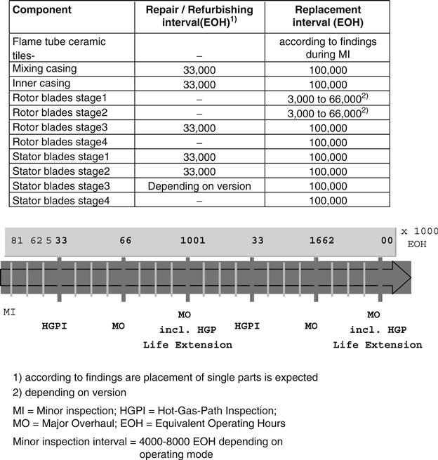
Nomenclature
EOH: Equivalent operating hours are determined from base load operating hours, the start/stop cycles and also operations such as turbine trips, with corresponding weighting factors. For example, 1 hour of operation at base load is defined as 1 EOH and 1 start with normal loading gradient is weighted 10 EOH.
LCF: Low-cycle fatigue
HCF: High-cycle fatigue
TIT: Turbine inlet temperature according to ISO definition
HGP: Hot-gas-path
HGPI: Hot-gas-path inspection
Maintenance Program and Upgraded Spare Parts
Not only the turbine inlet temperature has been increased but also the hot-gas-path (HGP) inspection interval has been extended from initially 16,000 equivalent operating hours (EOH) to 25,000 EOH and then to 33,000 EOH in 1994 (Figure 12–64). The application of the last step eliminates two hot-gas-path inspections within a plant’s life of for example 200,000 EOH. The table in Figure 12–64 shows the predicted service life data of hot components according to the design life under certain basic assumptions (natural gas firing, continuous duty etc.). Apart from the 33,000 to 66,000 EOH replacement interval for turbine rotor blades stage 1 and 2 the other hot components are scheduled for 100,000 EOH of operation. To allow this, the refurbishment intervals, also shown in this table, have to be met for these components. Service life extension involves the following cases:
• Components that are in good condition during overhauls and that have remaining useful life require no action to be taken and these components can remain in service.
• The physical condition of the component requires life extending repair measures, such as refurbishing of turbine blades, to enable further use of the component.
• The component is replaced with one of equal value.
• The component is replaced with one of higher value with focus on higher robustness, increased output, and efficiency.
As replacement options, hot component upgrades that have been developed during the design evolution of the V94.2 over the last two decades are available (Table 12–7). The decision depends on the condition of the component and on the assessment of possible remaining usable life. Evaluation of the cost and benefits of these possibilities have a significant influence on the choice.
TABLE 12–7
Upgrading V94.2 Hot-Gas-Path Components
| Component | Original | Upgrade | Latest Upgrade |
| Mixing casings, Inner Casing |
austenitic steel | Incoloy 800 H with higher strength, improved cooling | Inconel 617 with higher strength, improved cooling |
| Rotor blade stage 1 | IN738LC, serpentine cooling, chromized | improved cooling by additional turbolators | separate cooling channel at leading edge, VPS coating SICOAT 2231 |
| Rotor blade stage 2 | IN738LC, uncooled, chromized | cooling with 6 radial bores | improved cooling with 12 radial bores, VPS coating SICOAT 2231 |
| Rotor blade stage 3 | Nimonic 90 | U520 or U720 with higher strength, chromized | IN738LC, new design, aerodynamic improved |
| Rotor blade stage 4 | Nimonic 80A, damping pins | Nimonic 90 with higher strength, free standing blade without damping pins is more efficient | U520 with higher strength, new design, aerodynamic improved |
| Stator blade No. 1 | IN738LC, chromized | improved cooling | improved cooling, VPS coating SICOAT 2231 |
| Stator blade stage 2 | U500, chromized | IN738LC with higher strength | VPS coating SICOAT 2231 |
| Stator blade stage 3 | U500, chromized | IN738LC, chromized | IN939 uncoated |
| Stator blade stage 4 | austenitic steel, segments | N155 with higher strength, single airfoils | IN939 with higher strength |
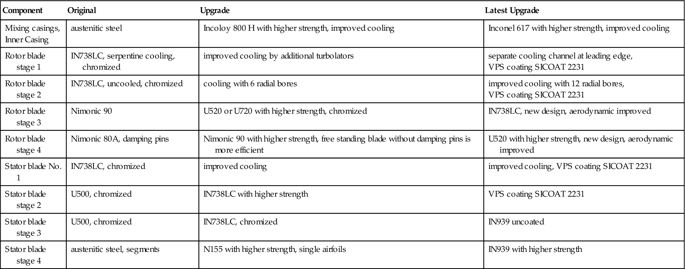
(Source: Siemens.)
A life assessment of all V94.2 hot-gas-path components is reported below. By detailed material investigations on turbine blading of the front stages after 33,000 EOH of operation, valuable experience has been gained. Several hot components that we have monitored and investigated have proven potential for further extension of the HGP inspection interval to longer assessment of the other hot components after 100,000 EOH of operation is reported.
Hot Component Life Assessment Procedure
The hot component life assessment procedure has to be based on the design criteria for these parts.
Design Criteria
Turbine blading is designed, based on creep strength for a period of 100,000 equivalent operating hours and, in the V94.2 turbine, is made of nickel-based alloys.
Surface coatings are applied to the front stages to protect the base material from high-temperature corrosion and oxidation. These coatings are consumed and are then renewed, e.g., after one hot-gas-path inspection interval of 33,000 EOH.
Depending on the blade row, thousands of starts with normal loading gradients or hundreds of turbine trips are taken into account. The resulting loads are caused by changes in mechanical forces such as centrifugal force as well as restrained thermal expansion and are partially in the plastic range. This type of loading is characterized by low-cycle fatigue (LCF) strength. The number of load cycles, which can be achieved, is mainly dependent on the extent of plastic strain and component temperature. Furthermore the rotor blades are designed for withstanding high-cycle fatigue (HCF). This means that the effects of vibration caused by rotor dynamics, aerodynamic, and combustion effects are below a certain stress value so that the component can be exposed to essentially unlimited numbers of stress cycles occurring at high frequency.
The mixing casings and the inner casing are designed similarly to the turbine blading based on creep strength and low-cycle fatigue strength. As casings in the hot-gas-path are exposed to significant low-cycle fatigue loading, these components require regenerative heat treatment and weld repair during hot-gas-path inspections.
Design criteria are established according to the different loads in the operated gas turbine and calibrated on measurements with gas turbines in test beds and in operation. The sophisticated and validated philosophy and criteria for design, manufacturing, repair, and quality assurance is fully available only at the original manufacturer.
Life Assessment
Based on the design philosophy described above, the residual life assessment encompasses stress analysis, operation, and repair history, quality control as well as material investigations of the service-exposed parts.
A preliminary step for plant life extension involves the compilation of all operating data such as the number of starts, hours of operation, and rapid temperature changes (e.g., due to load rejection or turbine trip, Figure 12–65).

The history of maintenance measures and the trends of findings of the most recent fact-finding on minor and major inspections must also be accounted for.
Following selection of the components to be considered, the corresponding original design criteria and corresponding analysis are used and updated if necessary.
Material investigation corresponding to the design criteria includes both non-destructive evaluation and destructive testing of components:
• Visual examination is first required to determine whether a blade has sustained oxidation/corrosion. This is followed by surface crack examination. Selected areas are then subjected to metallographic examination to evaluate the surfaces with regard to consumption of the protective coating, the depth of attack in the base material and for assessment of the microstructure. Investigations with the scanning electron microscope of the γ′-phase may be included if useful.
• Creep tests are performed on selected components, the samples being taken from the blade airfoil out of areas of the highest loading. Test time is reduced by performance at test temperatures that exceed the metal temperature in operation and by increased test stress levels above the operating stress. The same tests are performed for comparison purposes on samples from the blade root, which is not subjected to creep.
• Corresponding low-cycle fatigue tests are required to enable conclusions regarding low-cycle fatigue strength, the material property used for evaluation of service life expenditure caused by starts/stops, and rapid temperature changes. These tests are performed at room temperature. Samples from both the blade airfoil and root are also tested here. Results can then be directly compared with the low-cycle fatigue strength design curve, the lower bounding curve.
Crack examination yields preliminary indications of exceeding high-cycle fatigue strength. In the event that cracks occur due to cyclic loading, these can be assigned to loading based on the crack initiation site and crack propagation. If the blade is free of cracks, the design strength and the high-cyclic loading limits are used for further evaluation. An example of such investigations is described below.
Based on these material investigations, the original design and mode of operation of the gas turbine, and reusability of the component(s) in question are evaluated from a technical standpoint. Following consideration of the costs and benefits of measures such as requisite repairs, the final decision is made regarding continued use or replacement.
Hot Component Life Extension
The rotor blades and stator blades of stage 1 and 2 are highly temperature loaded, internally-cooled blades, and rotor blades stage 1 and 2 are designed with low wall thicknesses. Stage 1 and stage 2 are coated with a highly efficient coating on the outer surface. Compared to stage 1 and 2 the stages 3 and 4 are moderately temperature loaded. Apart from the moderately cooled stator blade stage 3 the other rows are uncooled solid airfoils so that life limiters such as internal oxidation or low wall thickness do not play a role here.
All turbine blade stages showed excellent creep strength during operation. No failures, negligible creep deflection, and excellent microstructures of investigated blades have been found.
Stage 1 and 2 of the Turbine Blading
Rotor Blade Stage 1 (Tla1)
The original design of the Tla1 was developed in the late seventies. This blade already uses—compared to the state of the art in those years—an advanced serpentine type convective cooling channel. Turbolators have been added to the cooling configuration over the years. The cooling holes at the trailing edge had to be electrochemically manufactured (ECM) at that time. Since then, several steps of increasing turbine inlet temperature have been carried out. The original design revealed several findings during the refurbishment after 33,000 EOH of operation. This led to the decision to limit the service lifetime to one hot-gas-path inspection interval of 33,000 EOH. The findings were mainly:
• Considerable loss of wall thickness due to oxidation at the outer surface for the chromized type of this blade
• Significant internal oxidation especially at the trailing edge that caused certain cracking at the cooling holes in combination with cyclic operation due to LCF
• Occasional LCF cracking of the leading edge due to cyclic operation
Therefore, about 6 years ago this blade was redesigned with several features. Due to the progress in casting technology it was feasible to cast-in cooling outlet slots instead of the ECM manufactured holes. This measure resulted in a reduced concentration factor, thus significantly improving the low cycle fatigue strength. The outlet slots were provided with six rows of cylindrical pins to connect the suction side and the pressure side. These pins increased turbolance effects and enlarged the cooling surface for a more effective heat transfer.
The cooling of the leading edge was improved by a separate cooling channel with turbulators and a cooling air outlet at the blade tip. Additionally this feature made the airfoil more resistant against potential foreign object damage.
Additionally this blade was protected with the MCrAlY type vacuum plasma spray coating SICOAT 2231 on the outer surface.
A systematic life assessment program was carried out on service exposed rotor blades stage 1 after 33,000 EOH of operation to verify these improvements.
Samples from base load units revealed excellent coating behavior even at the leading edge, which is the position of the highest material temperature. It retains still usable coating and therefore potential for longer refurbishment intervals.
A unit being operated at intermediate duty with numerous start-stop cycles over one HGP inspection interval showed comparable excellent coating behavior. Only at the leading edge was the coating nearly consumed while other regions looked as good as new.
The leading edge of the upgraded design, opposite to the original design, showed no crack indications after comparable operating conditions. Also no notable internal oxidation was found with the upgraded design. This is of special interest for the life of the trailing edge. The trailing edge of the upgraded design was found crack free in all cases.
In addition a microstructural temperature evaluation by investigating the coarsening of γ′-phase was performed for the leading edge. In accordance with the computational analysis this investigation showed that the material temperature is about 50°C lower compared to the original design (Figure 12–66).
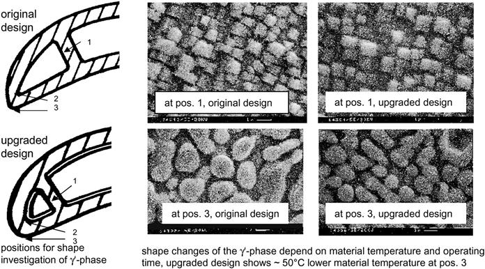
With the upgraded design the usable life of the Tla1 has been extended by 100% from one to two HGP inspection intervals including the refurbishment after 33,000 EOH.
Rotor Blade Stage 2 (Tla2)
The MCrAlY type SICOAT 2231 protective coating was implemented to the outer surface of rotor blade stage 2 as well. On samples taken from such blades after service, excellent coating and base material conditions have been investigated after one HGP inspection interval of 33,000 EOH in every case. One example in Figure 12–67 shows a still usable coating thickness of >150 m and no base material attack, as was the case with the chromized type. Therefore, with this enhanced coating, comparable to the Tla1 the usable life of the Tla2 has been extended by 100% from one to two HGP inspection intervals including the refurbishment after 33,000 EOH. The enhanced coating is not only applied on new blades but also available for the blades of the original design.
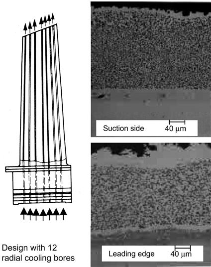
Stator Blades Stage 1 and 2
These rows are also supplied with the above-mentioned SICOAT 2231 coating to meet the refurbishment intervals of 33,000 EOH. The refurbishment includes cleaning of the oxidized outer surface by the SICLEAN® method, recoating of the outer surface and potential repair of thermally caused cracks at the trailing edge. During refurbishment the internal cooling passages also require nondestructive surface testing. With increasing operating time, degradation of the internal cooling channels accumulates and also repair measures might not be allowed several times on the same blade. Therefore the scrap rate increases with the number of refurbishment cycles and refurbishment after reaching the 100,000 EOH milestone is considered to be not realistic for these blades.
Stage 3 and 4 of the Turbine Blading and Hot-Gas-Path Casings
Stator blades in stages 3 and 4 undergo residual life assessment when reaching the 100,000 EOH milestone, as they have potential for continued service. Highly influenced by the operating and repair history and also depending on the material and design variant, the inner casing and the mixing casings are assessed for their residual life after 100,000 EOH.
In summary, life extension options for hot components during regular HGP inspections and after long operating periods 100,000 EOH were studied.
Repair methods and protective coatings have been continuously improved for those hot components that need regular life extension measures during hot-gas-path inspections.
The investigations for life extension of hot-gas-path components after the long operating period of 100,000 EOH have revealed that several hot-gas-path components have definitely reached the end of their usable life, while others, e.g., rear rows of the turbine blades, may be usable for one more 33,000 EOH period or even longer.
Plant life extension including hot-gas-path life extension of V94.2 gas turbines has been applied on 11 gas turbines V94.2. Also a large number of additional plant life extensions are due to take place in the coming years. While the basic statements for life assessment and life extension are valid for the whole V94.2 fleet, it must be emphasized that each gas turbine needs to be evaluated individually because of its individual operating conditions. Up to now, life extension projects involved the early versions of V94.2 with relatively low turbine inlet temperature (TITISO) × 1000°C and with the original hot component design, while many of the future projects will involve a higher TITISO > 1000°C for base load operation with different hot component design.
The most profitable plant life extension projects:
• include not only residual life assessment of the hot-gas path components,
• but also focus on strategic maintenance aspects to use upgraded hot components for higher durability, longer inspection intervals, lower scope of inspection and overhaul work and subsequently higher plant availability,
• and also care for modernization opportunities to improve the performance and competitiveness of the operating plant.
The best way is to evaluate these items in a joint project involving the electric power producer and the gas turbine manufacturer.
Case Study 13: Assessing Performance Degradation in Gas Turbines for Power Applications25
In a combined-cycle configuration, due to lengthy commissioning activities of various systems, acceptance performance tests are conducted only after a significant number of hours in operation have been accumulated.
The degradation of gas turbine (GT) thermal performance is playing a significant role in the economic viability of the highly competitive merchant power plant market. In combined-cycle applications, the degradation impacts not only to the traditional performance guarantees for power output and heat rate, but also to GT exhaust flow and exhaust temperature.
This case addresses the impact on plant performance guarantees due to qualifications applied to degradation process terms such as “new and clean condition,” “fired and equivalent operating hours,” and “bench-mark testing.” In addition, the document will touch on how degradation evaluation may affect the long-term service agreements (LTSA) between owners and equipment manufacturers.
Since a gas turbine has several major components (compressor, combustor, turbine), interconnected mechanically and thermodynamically, any change in the behavior of one affects the others. It is therefore important, when examining degradation impact, to treat the GT as a “complete system.”
Compressor Degradation
Compressor degradation accounts for 70–80% of GT performance losses. Consequently, manufacturers focused their efforts on analyzing its degradation mechanism and effective means of performance recovery. For a large industrial turbine, a drop in compressor isentropic efficiency by 1% causes a reduction in output of 1.2%. A combined effect of 1% decrease in airflow and efficiency yields a 1.8% power output reduction and an increase of 0.8% in the GT heat rate. There are two major contributors to loss of output and efficiency:
• Compressor airflow reduction
• Compressor increased aerodynamic losses operation in adverse pressure gradient
Erosion, corrosion, and fouling change the blades surface roughness and shape and affect both compressor capacity and optimal aerodynamic behavior. Compressor capacity is further reduced due to increased parasitic airflow caused by larger gaps in seals and clearances. The reduction in capacity is typically 1.6 times the drop in compressor efficiency. It should be noted that local degradation has a chain effect.
If a particular compressor stage has a higher loss, the stage exit pressure falls, the temperature increases, and all other stages operate at mismatched conditions.
Fouling
Fouling is caused by adherence of particulates, usually smaller than 3 μm in diameter, to the surface of airfoils and air passages. The water mist from the inlet air and oil leaks are the main bonding elements for these ingested particles. Lubrication oil is drawn into the flow path, due to the low-pressure upstream of the first rotor. While the oil acts only as glue for the first few rows, the increased temperature at the subsequent stages of the compressor causes the oil to form coke deposits.
Modern transonic compressors, operating near choking conditions, are particularly sensitive to fouling. Material build-up and thicker boundary layers, due to surface roughness, accentuate the airflow reduction. Heavy-duty industrial gas turbines operating at constant speed experience a more severe loss of capacity, since they cannot compensate for the loss by rotating at a higher speed. The fouling of the first stage will reduce the mass flow (flow coefficient) and the performance of the following stages will be affected. The operating point of the first stage will move from the design point to a higher pressure, higher density at the inlet of the second stage and a further flow coefficient reduction. The phenomenon of propagation in the following stages could eventually trigger a surge.
Erosion
Large particles, typically 20–30 μm in diameter, passing through the flow path have an abrasive impact on the airfoils. The result is removal of material and increased surface roughness. For industrial gas turbines, this problem is less severe because of extensive utilization of inlet air filtering systems. The recent use of inlet fogging or wet compression systems has the potential to cause damage if large droplets of water hit compressor blades. Blade erosion degrades the aerodynamic performance and could also generate structural problems. Due to several problems with the first rotating blade of the compressor, some of the manufacturers insist on using only their own design for an online water wash system (rather than a generic one) and imposed limitations in the use of inlet fogging for extended periods of time.
Clearances
During GT operation, the clearances between stationary and rotating parts have a predisposition to widen, resulting in substantial increases of parasitic flows (leakages). Of particular significance are the tip clearances between the rotating blades and the stationary casings. The increased leakage flow bypasses the stage and mixes lower pressure air with the mainstream air. The result is a lower pressure head at the stage exit. An increase of rotor tip clearance from 1% of blade chord to 3.5% of blade cord reduces the pressure ratio of a stage by up to 15%.
It is important to note that a reduction in pressure rise negatively affects the compressor surge margin and consequently the operational range. Another source of increased airflow leakages is reduced inter-stage labyrinth seals’ tightness. Obviously the mode of GT operation affects the pace of degradation. During the initial “engine break-in,” axial or blade tip rubs occur and result in increased clearances, which quickly reach nominal values. After this initial period, the clearances will remain relative constant over time. Fast loading and unloading of the gas turbine, trips, and load rejection events accelerate the widening of the clearances and cause more rapid degradation.
Turbine Degradation
The typical causes of turbine degradation are associated with alteration in airfoil geometry (leading and training edge thickness, surface roughness, and profile changes) and increase in parasitic losses (tip clearances, secondary and cooling air).
Degradation can alter the amount and distribution of the secondary cooling air, which might create severe overheating of metal surfaces and low efficiency/high blockage of the flow path. In the absence of cooling air, the component damage could be extensive, beyond salvage. Worn seals, enlarged clearances, and damaged cooling flow passages have a substantial negative effect on performance. Larger amounts of cooling air either bypass the blading without producing work or enter the main exhaust gas stream at a wrong location, spoiling the flow high momentum. A poorer turbine section efficiency of 1% has a powerful impact on the GT performance, causing a 0.8% power output drop and 0.5% worse heat rate.
Combustion Degradation
While the combustion process efficiency is unlikely to decrease, the degradation impact on the combustion system is felt in several ways:
• Change in the burner geometry—This affects the combustion process and increases emissions due to either hot spots (higher NOx) or cold spots (higher CO). In particular, the dry low NOx (DLN) burners, which have very lean premix flames and require precise tuning, are extremely sensitive to even minor burner and combustion chamber alterations.
• Change in the exhaust temperature distribution. A distorted combustion profile may alter a predetermined control temperature setting, either under-firing or over-firing the GT. In each case, the results are not desirable, causing loss of power (under-firing) or reducing components' life (over-firing).
• Change in pressure drop across the combustor—This affects the gas flow through the turbine, since the combustor exit pressure is proportional to P turbine inlet plane.
• Change in the secondary cooling flows—Combustor metal liners are affected by erosion and corrosion, which increase the cooling air holes and thus the cooling air consumption. On the other hand, fuels containing ash might partially block the cooling holes, creating high temperature spots on the liner surface.
External Factors Affecting Degradation
Gaseous Fuel
In general, gaseous fuels are considered more suitable than liquid fuels for continuous base-load operation. Fuel quality has an important role in performance degradation of gas turbines. The ideal fuel is a clean, dry gas, with a low sulfur content, which can originate from different sources: pipeline quality natural gas, vaporized LNG or LPG, and process synthesis gas.
Fuels containing traces of metal create deposits on the nozzles and blades, impacting GT integrity and performance. In one particular application, Ni deposits concentrated on the tip of the burner forced a burner redesign. In many other cases, the deposits plug the blades’ cooling holes and create areas of overheating, which eventually lead to cracks in the material. Special coatings on the blades are often used to minimize the corrosion. Another negative effect of deposits, as mentioned above, is accelerated thermal performance degradation. In the current market, with gas prices near record levels, increased demand, and strained supplies, there is little incentive for the producers to maintain a consistent gas quality. Traditionally, gas liquids, such as propane and butane, were removed and sold as chemical feed-stocks because their value was higher than in the fuel gas market. Not any more.
Some experts estimate that as much as one third of the gas produced in the US is no longer processed to remove liquid hydrocarbons. Therefore, the physical and chemical characteristics of pipeline gas are significantly different from the “original design fuel.” This “out of specification fuel” can create mechanical problems and accelerate the degradation process.
Liquid Fuel
Heavy-duty gas turbines are capable of burning a variety of liquid fuels, ranging from light petroleum distillates to heavy residuals. The combustion process of light distillates such as naphtha, kerosene, and No. 2 fuel oil is well understood and has been proven through millions of hours of operation. The degradation rates on these types of liquid fuels are predicted to be 20% higher than on natural gas fuel. The real challenges for GT design and operation come from the use of heavier ash-forming fuels. The combustion of these fuels can be extremely detrimental to GT life, due to corrosion, erosion, and fouling of the blades. Hot corrosion, caused by traces of elements such as sodium (Na), potassium (K), lead (Pb), and particularly vanadium (V) in the fuel, has a major effect on GT performance and the service life of the hot gas path. The number of equivalent operating hours (EOH), which serves as the basis for degradation and maintenance intervals, increases more rapidly based on fuel contaminant concentration, accounting for a factor of 1.5 for each operating hour (by certain estimates).
Water
The effect of water on GT degradation depends on its use and point of entry. At the inlet of the compressor, droplets of water generated by the fogging system may cause erosion on the blades and corrosion of the inlet ducting and plenum. Water and steam injection in the combustion system is used for NOx reduction. On one hand, the increased hot gas mass flow causes a rise in the pressure ratio and power output. Thus, the mechanical loading of the blades is higher. On the other hand, the higher moisture content in the hot gas affects the heat transfer properties and consequently increasing the metal temperature of the blades. Finally, exposure to gases with higher moisture content reduces the wear resistance of the turbine blades' coatings. Therefore, a weighting factor on the number of operating hours should be applied as a function of the amount of water injected.
Marine and Offshore Environment
The airborne salt in different forms (aerosol, spray or crystal) is impacting the fouling of the compressor. High environmental relative humidity causes the salt to remain as supersaturated droplets. The database concerning the amount and form of the salt content indicates considerable variation and dependency on the wind speed on the level of contamination.
Means of Reducing Degradation
Recoverable and Non-Recoverable Degradation
The process of degradation cannot be avoided, but its impact on performance and hardware life can be mitigated by undertaking a number of preventive actions, starting with conceptual design, and continuing through the project execution and operation and maintenance activities. Here it is appropriate to introduce the definitions of recoverable and non-recoverable degradation. The recoverable degradation is considered the portion of the GT performance, which can be restored by a series of maintenance activities without opening the machine or replacing major parts. This degradation recovery is commonly achieved by conducting compressor washing and minor engine adjustments (such as resetting the inlet guide vanes). The remaining degradation is regarded as non-recoverable. Equipment manufacturers predict the non-recoverable degradation for the equipment in the form of degradation curves.
Figure 12–68 provides an example of recoverable degradation by online and offline compressor water wash. It should be noted that these notions of recoverable and non-recoverable degradation could be confusing, since after major overhauls, the GT performance can be restored to almost the level achieved in “new and clean” conditions.
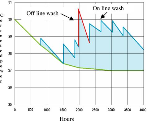
Limits on allowable degradation, recoverable and non-recoverable from base load conditions, should be established with the equipment manufacturers. Operating below these limits increases the risk of compressor surge. In the project development phase, the impact of the recoverable and non-recoverable degradation, scheduled outages, etc., should be duly accounted for in the project pro forma analysis.
Fuel Treatment
During the initial design phase, actual specifications should be provided for fuel quality entering the gas turbine. If GT manufacturer fuel requirements cannot be met, a comprehensive precombustion fuel treatment must be developed and implemented, aimed at reducing the concentration of contaminants. It is highly recommended to implement for gaseous fuels an online, real-time, continuous composition monitoring system, based on gas chromatography. The pretreatment process for liquid fuels should involve chemical reactions and/or mechanical systems. Na and K salts are soluble in water and can be removed by the on-site treatment known as fuel washing. Other methods of fuel treatment include the use of high-temperature corrosion additives. To reduce the amount of expensive additives, a preliminary step for improving fuel quality entails using of commercially available mechanical fuel treatment skids composed of centrifugal separators, pumps, and sludge tanks. The devices can reduce the concentration of harmful contaminants (Na, K, S, and V). A typical two-stage system can reduce the Na content from 150 ppm to 1 ppm for heavy salts.
Air Filtering System
The air filtering system must have the capability to eliminate 99.95% of all particulates above 20 μm, since these particles are the main source for compressor erosion. Installations located in the desert, in coastal areas or near dust emitting sources (coal dust, cement dust, fly ash, and pollen) should be equipped with self-cleaning systems that have an effective dust removal system. The ambient air for many combined cycles located close to refineries contains air-borne heavy hydrocarbon matter that eventually could sinter on compressor blades and cause non-recoverable degradation. In the absence of an efficient and proper designed inlet system, the ingestion of humid and salty air at a seaside location may lead to erosion and corrosion in the compressor as well as in the turbine section of the gas turbine. Finally, it is recommended that an ambient air quality analysis be conducted during initial site development, as extremely useful information.
Degradation Curves
To cover the gap from the “new and clean” performance guaranteed by the manufacturer to the performance measured during the test, equipment degradation curves have been created. The predicted degradation curve, in logarithmic shape, is a function of operational hours. This trend represents the non-recoverable degradation, which cannot be restored without opening of engine covers to refurbish the components back to a new and clean condition. Such events occur during hot gas path inspection or major overhaul. This cumulative degradation curve represents the contributions of each individual engine components. Since degradation, as described above, is not simply affected by the number of fired hours, some GT manufacturers created a methodology where degradation is a function of EOH, a weighted number of hours accounting for different operating conditions: type of fuel, number of starts, stops, trips, sudden changes in load, and use of diluents. For example, a normal start adds 10 EOH and each hour operating with water injection is considered to add 1.5 EOH. An hour of peak load operation at increased firing temperature equals 3 EOH. Some manufacturers indicate that each trip could represent between 25 and 400 EOH, depending on the GT load at the time of the trip. The determination of the weighting factor for each of the operational conditions on the EOH value is done solely by the equipment manufacturers. It is assumed that these factors are determined on the basis of the fleet performance experience and inhouse modeling.
Operations and LTSA (Long-Term Service Agreement)
Assessing the GT degradation is important not only for acceptance performance tests but also for day-to-day operations. Asset managers/operators should carefully plan the operation and scheduled maintenance of the gas turbine, to keep the number of EOH as low as possible. However, in the current opportunistic power market, decisions on the way to operate the equipment are guided by commercial considerations rather than technical. To mitigate the uncertainty associated with maintenance costs, many owners enter in a maintenance contract often called a long-term service agreement (LTSA). An LTSA typically commits the OEM or non-OEM service contractor to provide, on a relative, fixed price basis, parts and maintenance services for gas or steam turbines.
Commercially, an LTSA should offer many advantages to owners, including the predictability of relatively fixed long-term costs, while keeping the OEM motivated through performance bonuses to provide support and ensure a predetermined level of performance (see Thomson, R., and J. Yost. “Avoiding Pitfalls in Service Contracts.” Turbo Machinery).
An LTSA must be clearly written and discussed, so that the parties involved do not have false expectations about the extent of its coverage. In many LTSA the validation of the actual GT degradation is an important element of the agreement. The suggestions and recommendations concerning the evaluation of performance degradation made above should be implemented in the LTSA documents and carried out in the field.
Case Study 14: Remaining Life Assessment of Power Turbine Disks26
This case presents the results of a study conducted to determine the life expectancy of a power turbine disk. The purpose of the study is to revisit the original design calculations with current numerical computing techniques. By determining the state of stress and temperature in the vicinity of the stress concentrations, combined with material properties, the life expectancy of power turbine disks can be established.
Most industrial power turbines commissioned in the early 1970s have accumulated approximate 200,000 operating hours, well beyond the minimum design life reported by some OEMs. Operators running into this situation have to make decisions on whether or not to replace the most expensive rotors and disks. Some operators are willing to take certain calculated risks, in return to gain value through reliable life extensions. Their decision making would be largely based upon the real life expectancy of the components and the risk of failure.
Power turbine rotor disks are subject to high loads and moderate temperatures. Metallurgically, the remaining life of power turbine disks is in general limited by the remaining creep or fatigue life. When a failure occurs in a disk, it is usually due to the crack initiation in the serrations where the stress concentrations are the greatest. The design life limits established by OEMs on those power turbines were based on the technologies in the 1970s, e.g., analytical approach, past experience, and understanding of material response to the expected operating envelope. The objective of the remaining life analysis is to revisit the original design calculations with current numerical computing techniques and determine the real life expectancy of power turbine disks.
Background
Turbine rotor disks are highly stressed in the rim area where the blade root attachment occurs and in the hub of bored disks where high burst strength is required. Temperatures are moderately low in the power turbine disk hub but can be high in the rim depending on the blade and cooling design. Rotor disks are also subject to high cycle fatigue loads from blade vibration and low cycle fatigue loads from start/stop cycles.
A combination of high tensile strength, fatigue resistance and moderate creep resistance is required for disk materials (see Schilke, P.W., “Advanced Gas Turbine Materials and Coatings,” GER-3569F). The materials used for industrial turbines rotor disks in the early 1970s were high strength steels (Cr-Mo-V), 12Cr stainless steels, and Fe-Ni base super-alloys (e.g., A-286). Table 12–8 lists the chemical composition of common industrial turbine rotor disk materials.
TABLE 12–8
Chemical Composition of Disk Materials (% wt) [12-5]
| Element | ASTM-A470 Class 8 | AEI T-G | A286 Spec. MS-618A/D/E |
| Ni | 0.75 max. | 3.0–3.75 | 24.0-27.0 |
| Cr | 0.90–1.50 | 0.8–1.6 | 13.5-16.0 |
| Si | 0.15–0.35 | 0.30 max. | 0.40 max. |
| Mn | 1.00 max. | 0.25–0.55 | 0.50 max. |
| C | 0.25–0.35 | 0.25–0.35 | 0.08 max. |
| Mo | 1.00–1.50 | 0.40–0.60 | 1.0-1.5 |
| V | 0.20–0.30 | 0.10–0.15 | 0.10-0.50 |
| S | 0.018 max. | 0.025 max. | 0.025 max. |
| P | 0.015 max. | 0.025 max. | 0.025 max. |
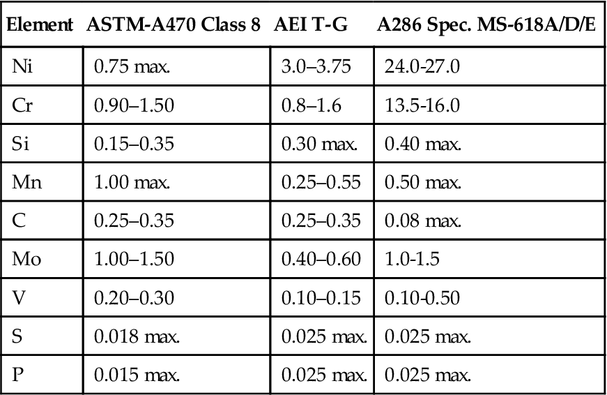
During service, turbine rotor disk materials undergo various types of time and cycle dependent degradations due to exposure in the operating environment. Data are rarely available for metallurgical characterization of gas turbine rotor disk materials after long-term service exposure. One reference reported material testing results of samples taken from a high-pressure steam turbine rotor that had been operated for 167,500 hours. The test results indicated that the rotor steel was slightly softened and temper embrittled as a result of service exposure after 26 years.
Metallurgically, the remaining life of power turbine rotor disks is in general limited by the remaining creep or low cycle fatigue life. High cycle fatigue (HCF) is not considered since HCF damage can be accumulated very rapidly under non-design conditions. As such, turbine rotors are not designed with an HCF life—they should have infinite life under normal operating conditions.
Technical Approach
Temperature, stress, and material are the three major factors determining life consumption. To estimate the temperature distribution across the rotor disk, an engine aero-thermal model, a blade external and internal heat transfer model, and an overall disk and blade assembly heat transfer model have to be developed. The engine aero-thermal model calculates gas path temperature, pressure, and flow. The calculated gas path aero-thermal values are then used as boundary conditions for the blade/disk assembly heat transfer analysis.
The blade root and disk interaction is quite complex. The blade root and disk groove have complicated geometries with numerous grooves where stress concentrations develop. Elastic-plastic deformation occurs, especially in the regions of the stress concentrations. The load applied to the blade root is transmitted to the disk via contact surfaces of the lands. The geometry of the blade root and disk can be measured using a computer-controlled coordinate measurement machine (CMM) or by a precisely calibrated optical comparator where the blade root and the disk root form casting are magnified by ∼10 times.
A plane strain/stress analysis of the blade root and disk interaction can be conducted using a finite element computer program to calculate stress concentrations or stress intensity factors. Temperature-dependent material properties have to be developed for the FEA model. When failure occurs in a disk, it is typically due to cracks that develop in the disk grooves where the stress concentrations are the greatest. With determining the state of stress and temperature in the vicinity of those stress concentrations, combined with the time dependent be estimated non-destructively. In this analysis, the disk was operated in continuous operation, so low cycle fatigue was not considered to be a life-limiting factor.
Geometry
The power turbine studied is a two-stage design with cooling air bleeding from the gas generator compressor to the first stage disk rim. The power turbine has accumulated 183,400 operating hours since installation in the late 1970s. The power turbine inlet temperature at ISO base load according to the published information is 1240°F and the exhaust temperature is 849°F. The same power turbine model is also packaged with gas generators with higher exhaust temperatures. The life expectancies of the power turbine disks under the elevated turbine inlet temperature conditions were also evaluated (Figure 12–69).
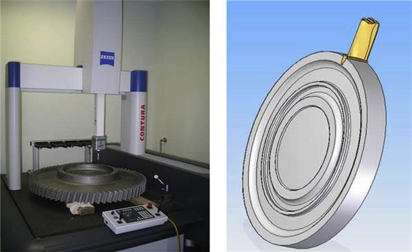
Aero-Thermal Analysis
Engine Modeling
To simulate the blade- and disk-operating environment, an aero-thermal model for the power turbine was developed. The aero-thermal model is a two-stage turbine mean-line program with the gas path geometry constructed from reverse engineering actual hardware. The aero-thermal program calculates hot gas path temperature, pressure, and flow across the turbine stages using the published power turbine performance data at the rated conditions. The calculated aero-thermal results relative to the stage 1 blades were then used as the boundary conditions for the blade heat transfer analysis.
Disk Cooling
The operating temperature of the first stage power turbine disk is strongly dependent on the cooling air temperature inside the front disk cavity. The power turbine rim cooling system is a series of pipes, connectors, flexible hoses, drilled nozzle vanes and temperature probes. Cooling air is bled from the gas generator intermediate compressor stage to the power turbine first stage disk rim and nozzles. It is designed to protect the first stage turbine disk from the extreme heat of gas generator exhaust gases.
From the power turbine historical operating data, it was found that the measured disk cavity temperature is a function of power turbine inlet temperature (Figure 12–70). The average measured disk cavity temperature based on the typical power turbine load conditions was used in the analysis.
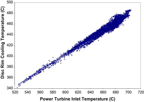
The case goes on to detail work that involved blade/ disk heat transfer calculations, peak stress, stress relaxation, creep rupture, probabilistic modeling, and then life expectancy calculations. Comparisons can then be made between different turbine disks. The calculations are too lengthy to repeat in this case.
In summary, an engineering approach has been developed to analyze real life expectancy of aged power turbine disks. The approach integrates mechanical design, analytical calculation, aero-thermal analysis, finite element modeling and probabilistic modeling of material properties. Applying the approach to a power turbine disk with 183,400 service hours, it was found that the disk could run for an infinite life assuming continued operation at the current conditions.
This conclusion is consistent with the result of a non-destructive examination conducted prior to the analysis. The dimensional inspection indicated no measurable plastic deformation per engineering drawings, while fluorescent penetrant testing found no cracking. The good dimensional stability after 27 years of operation suggests that it is unlikely the disk will fail due to primary stress related ductile bursting in the near future.
Since the power turbine inlet temperature and cooling air system have a significant impact on the disk metal temperature, and hence the life, operators should implement a fleet-wide monitoring program that would include the disk cavity temperature measurement and periodic inspections for any unforeseen damage mechanisms to ensure safe long-term operation of their power turbine disk fleet.